helvenco AERO 1000 User manual


2
Index
Page
3Important terms
4System installation
5System dimensions
6-9 Engine preparation
10 Wiring diagram
11 Fuel pump installation
12-14 Exchange of PTO pulley
15 Clutch drum position
16-18 Exchange of propeller pulley
19 Belt tension
20-21 EFI installation guide
22-23 Start-up
24-25 Maintenance & Oil change
26 Speed Conversion table & Reset ECU DTC codes
27 Goodwill and warranty regulations
28 Voucher

3
Important terms
helvenco AG assumes that the user has read, understood and accept the terms below
before operating the engine. They are helpful for a better understanding of the product
and useful to prevent and to minimize the risks.
helvenco AG only supplies OEM’s and specialized aviation engine distributors that have
sufficient technical knowledge to ensure the AERO products of helvenco AG are installed and
serviced/repaired correctly.
helvenco AG emphasizes that the AERO product line is not certified and is made for
experimental aircraft only. It is important the user understands that the engine can stall/or break
with an emergency landing as a result; this can occur to injuries or death! The AERO1000/1500
should be used in open spaces only and during daylight. This product is neither covered by
product nor public liability.
Who flies with a paramotor/experimental aircraft/ULM or even just starts it, automatically
assumes all the risks inherent to these sports and all the responsibilities for damages to yourself
or to third parties, accidents, injuries or death caused by using such products.
To fly with a paramotor/experimental aircraft/ULM always needs great attention. Be aware that
you fly at your own risk; always check if your machine is in good condition before use.
helvenco AG doesn’t assume any responsibility for damages caused by poor servicing or wrong
assembly.
Any modification on the standard AERO product made by any party other than helvenco AG can
make the product dangerous to be used and is on own risk.
Wrong mounted, bad balanced or unproportioned propellers can lead to serious damage of the
AERO1000/1500 products.
The engine can’t be used for acrobatic maneuverings.
Don’t use the AERO1000/1500 in bad weather conditions such as rain or snowfall.
Not limitative list of possible reasons leading to premature engine failures:
•Engine modifications not approved by helvenco AG.
•Carelessness, lack of servicing, accidents, installations or wrong maintenance.
•Accidental falls or engine drop or drop of its components.
•Improper use or misusage of the engine.
•Assembly of parts or components not specified for the engine use.
•Engine overheating or stop after long usage, beyond the term indicated by helvenco AG.
•Use of improper petrol or oils, presence of dirty parts or foreign bodies in the engine.
•Permanent/ too long running into the rpm limiter.
•Engine or parts deterioration because of improperly storage.
•Wrong engine assembly, including the use of not original helvenco AG parts.
•Damages to the engine caused by foreign bodies.
•Usage of wrong spark plugs.
•Not respecting the manual in general.

4
System installation
The system comes with 8 pre-installed silent blocks on the front plate. These are the fixation
points to install the AERO1000 system on your vehicle! You can change the position of the silent
blocks on the front plate. Below you find the dimension sheet!
The OEM must use an optional backup system (Ex. steel tie-wraps or tension strap) between
the AERO1000/1500 system and the frame it is attached to. If not, the user must contact the
OEM.
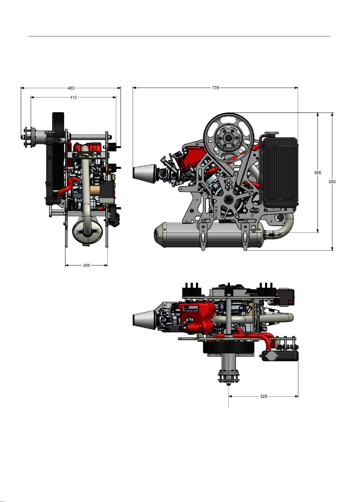
5
System dimensions

6
Engine preparation
Remove all plugs:
-Intake port
-Exhaust port
-Breather tube

7
Engine preparation
Place the system on the table as
shown.
Install the 2 feet and the exhaust
manifold.
Screw on the 2 self-locking M6 nuts.
Just tighten them a little bit so you can
still turn the manifold by hand.
Tighten them correctly after
installation of the exhaust muffler.

8
Engine preparation
Install the exhaust muffler.
Connect the 2 cradles with the silent
blocks below the engine mounts and
push the manifold into the exhaust
muffler.
Tighten all 4x M6 lock-nuts
Add the 2 exhaust springs
Finally tighten the 2 M6 lock-nuts at
the engine exhaust port.

9
Engine preparation
We have prepared installation points for the start/stop switch, the starter relais
and the ECU. You see them on the photos above. They are not installed!
Depending to the installation setup you have the choice to go to our positions or
to your own installation.
Install the other 2 feet. Now you can
place the engine upright.
Once the engine is installed on the
frame you can remove the feet.
10
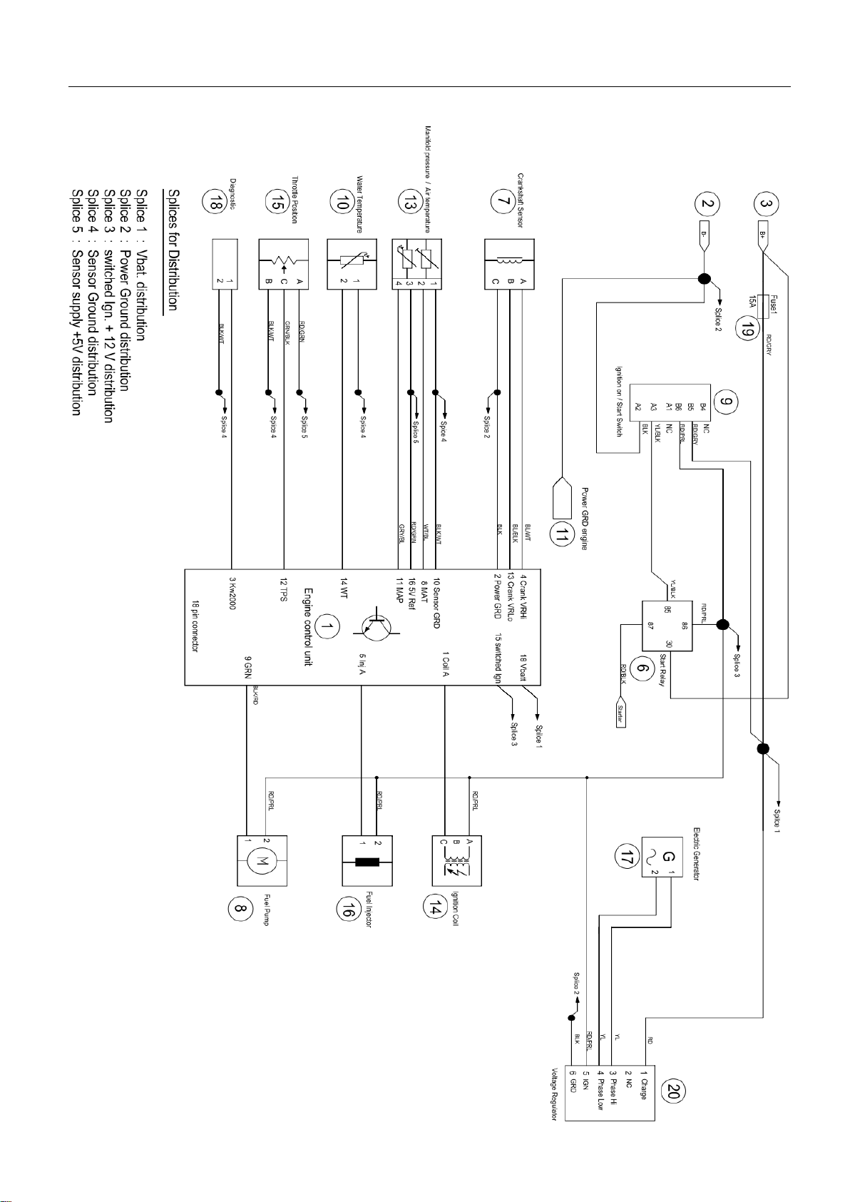
Wiring diagram
11
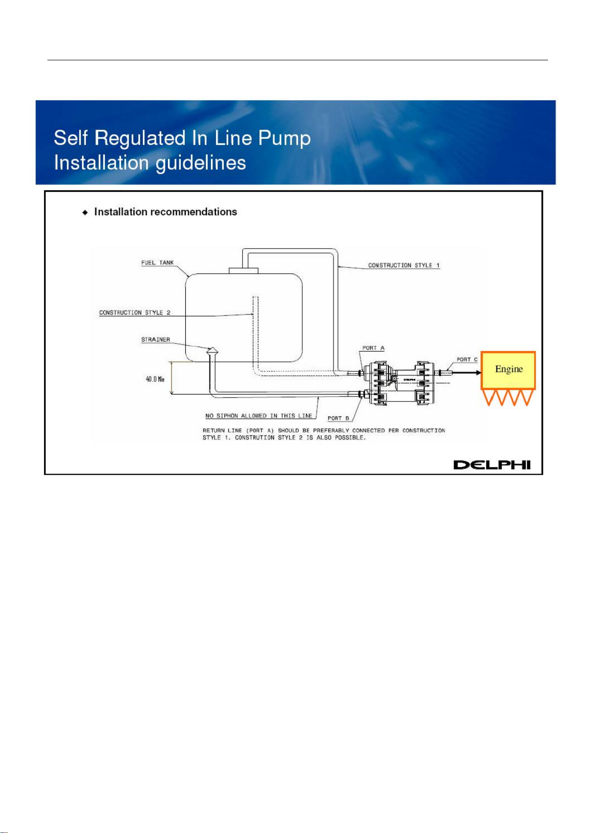
Fuel pump installation
The fuel pump isn’t self-bleeding!
Pump and all fuel hoses must be filled with fuel before running. Else the pump
gets damaged.
The pump must be installed below the fuel tank in the shown orientation!
To avoid engine stall, Port C must be higher or equal level with Port B!
Only use the quick release connectors that came along with the fuel pump.
The pump creates 2,5bar on the pressure line Port C! Only use the supplied
pressure hose and secure it on both sides with hose clamps to the connectors.
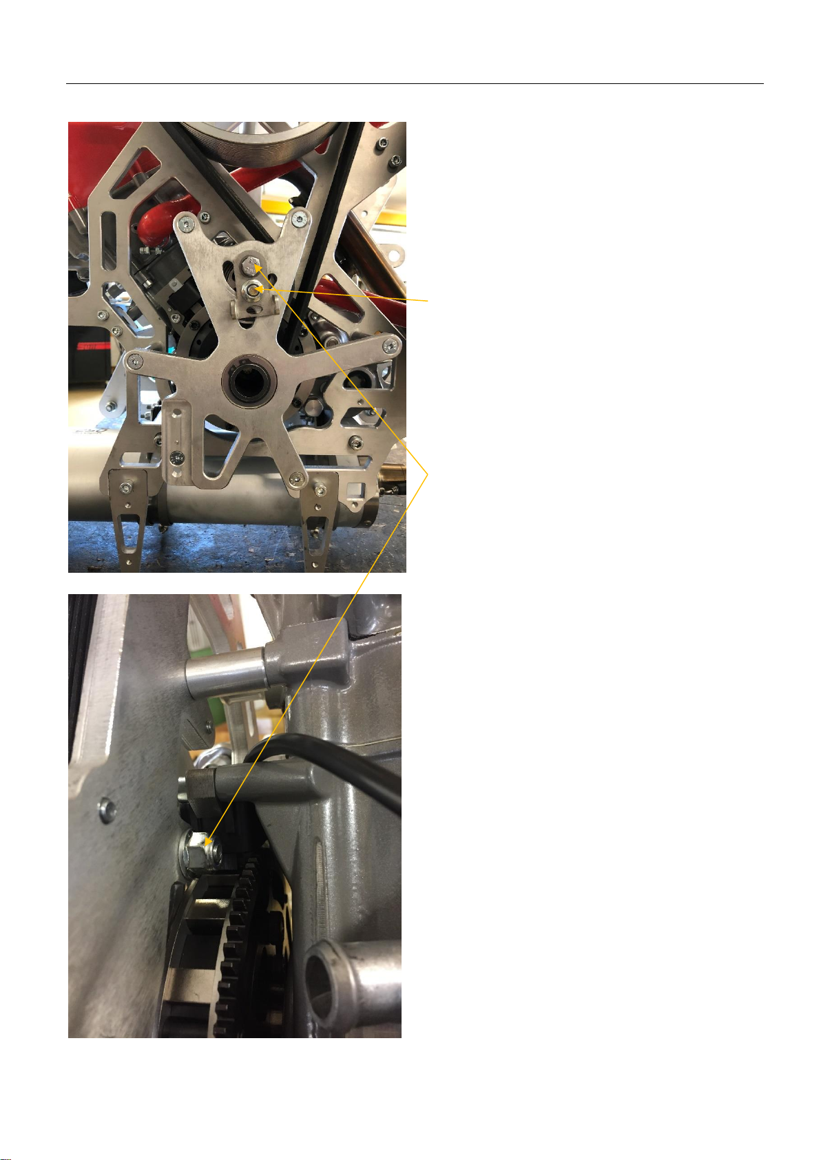
12
Exchange of PTO pulley
Unbolt the M8 self-locking nut
(Don’t remove)
Remove the M8 self-locking nut at the
back of engine back plate.
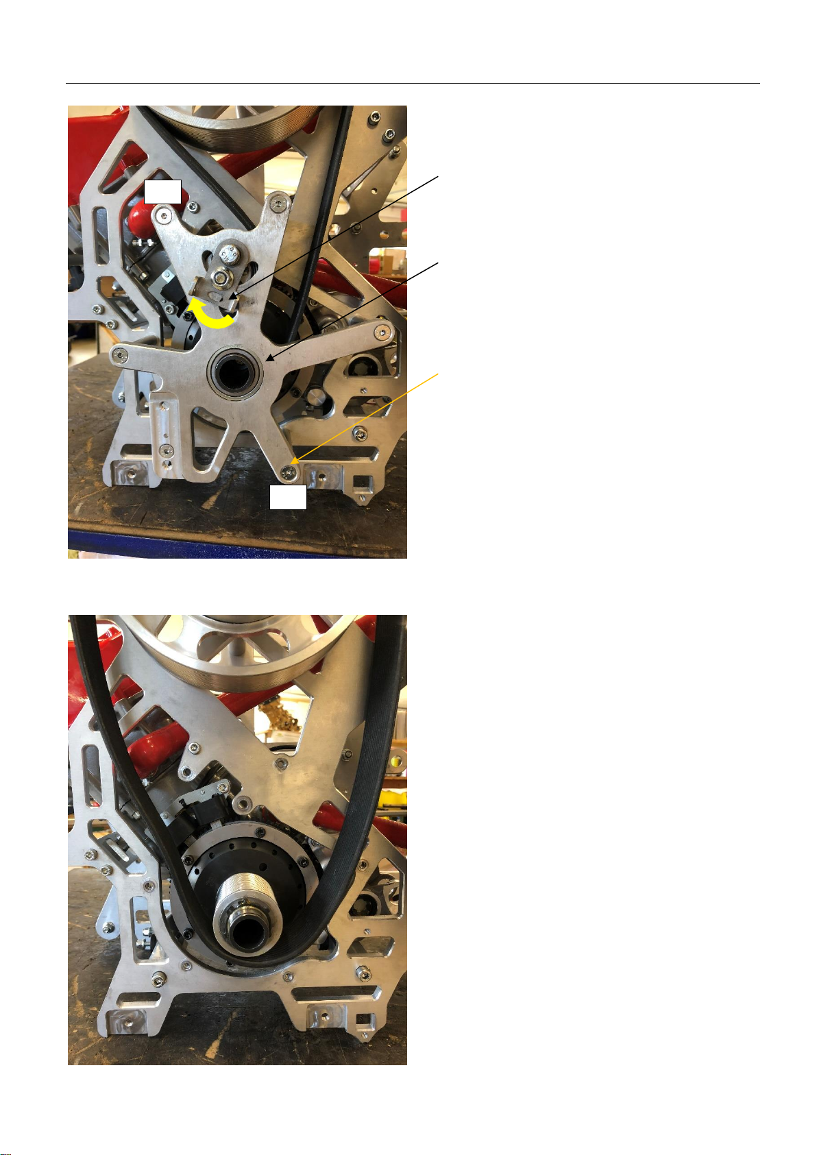
13
Exchange of PTO pulley
Release the belt tension by moving
the belt tensioner lever.
Remove the circlip and the distance
shim from the PTO shaft.
Remove all 6x M6 screws from the
PTO support plate.
ATTENTION!
Hold the distance sleeves when
remove the 6x M6 screws else the
will drop!
At re-installation of the PTO plate:
For correct outlining, always
tighten first screw #1 & #2 before
all others!
Remove the PTO support plate incl.
belt tensioner.
Remove the belt.
#1
#2
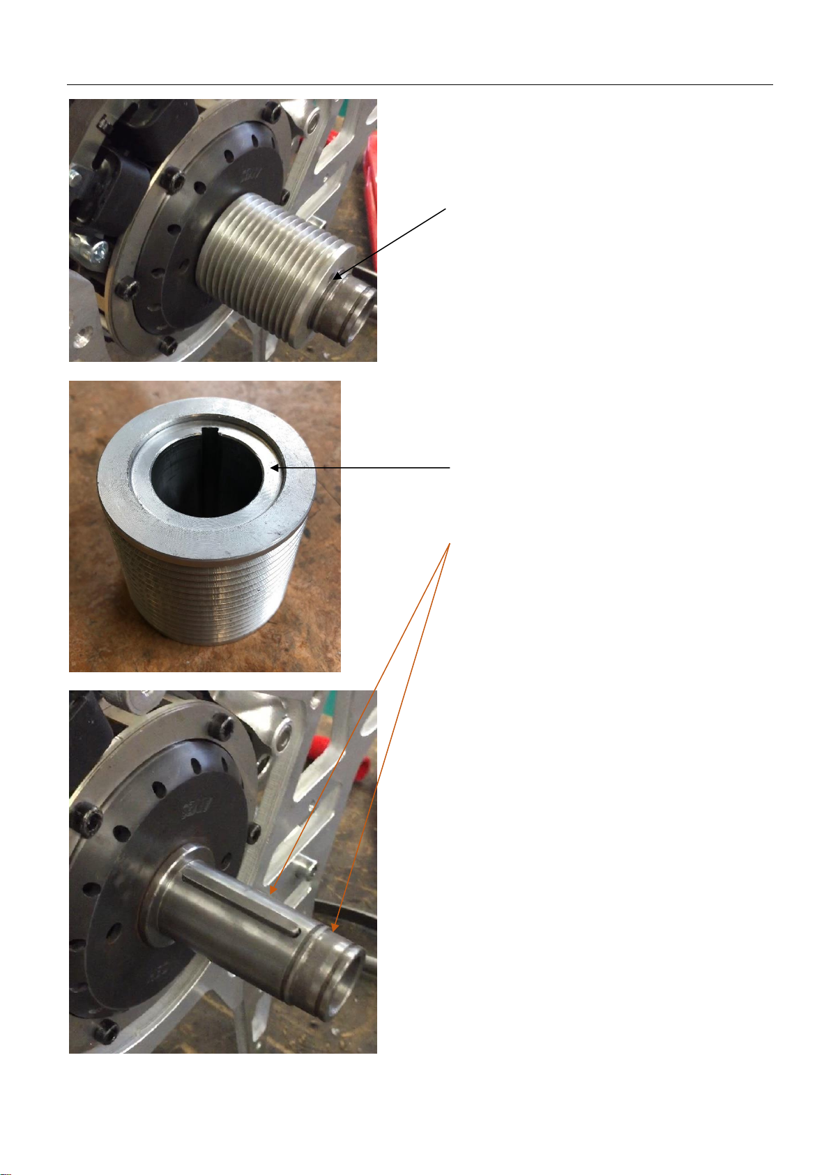
14
Exchange of PTO pulley
Remove the circlip and the distance
shim from the PTO shaft.
Remove the pulley and add the new
one.
ATTENTION! For correct belt
alignment mount the offset at the
pulley to engine side.
Always put anti-seize grease or
copper grease on the PTO shaft
before adding the pulley and PTO
plate.
Re-mount distance shim and circlip.
Install the PTO support plate inclusive
the belt tensioner.
Add the 6x M6 screws inclusive its
distance sleeves.
Fit the M8 self-locking nut at the back
of engine back plate.
Tighten the 6x M6 with following
torque: 10Nm / 7,37 ft-lb
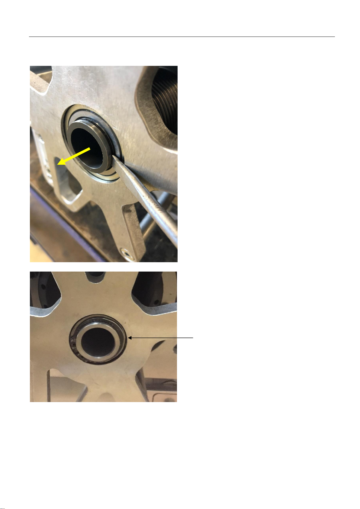
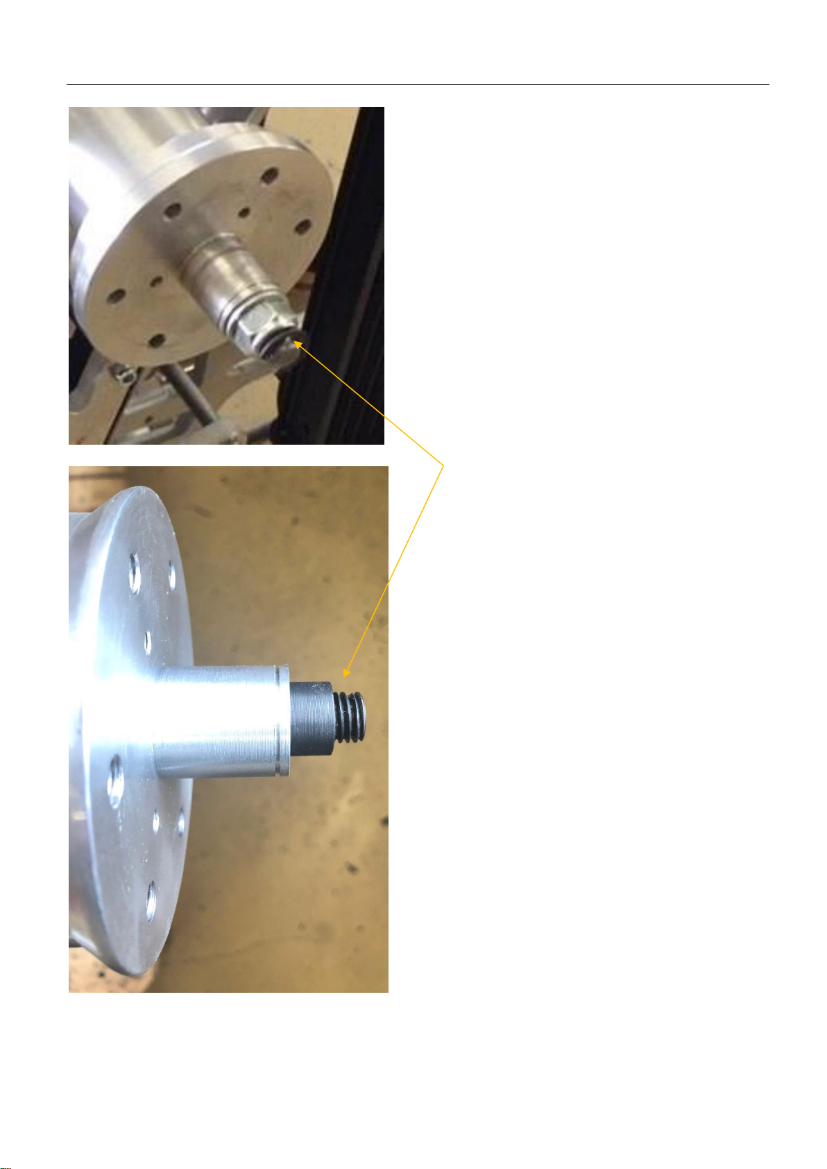
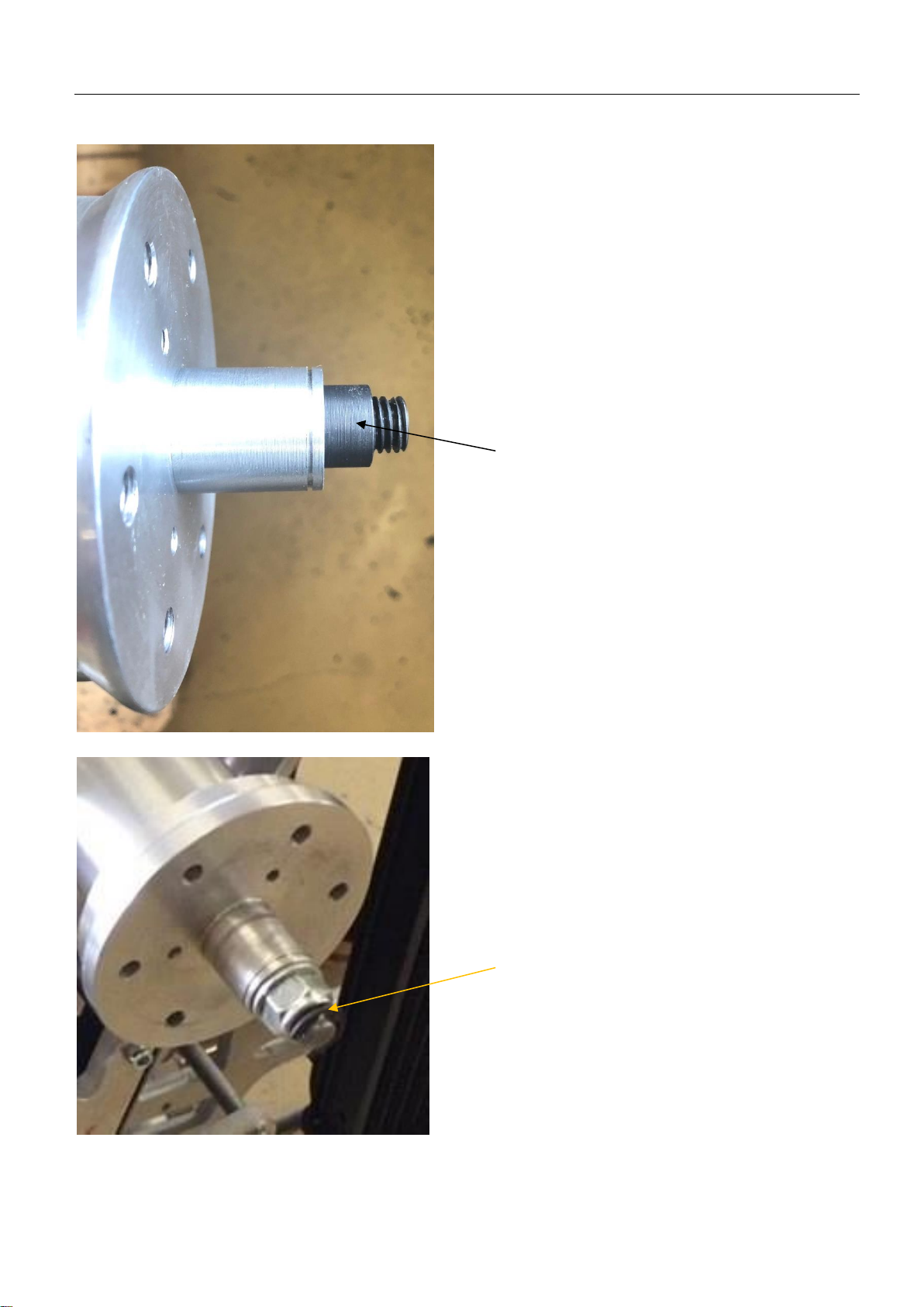
15
Clutch drum position
For correct alignment of the clutch
drum use a screw driver and pull out
the PTO shaft as shown.
It should easily move ± 0,5mm / 0,02
inches.
Now you can add the distance shim
and the circlip.
16
Exchange of propeller pulley
Remove the clip, unbolt the M12 self-
locking nut.
Remove washer and the black
pressure bush.
Now it is possible to remove the
complete propeller hub from the shaft
by pulling.

17
Exchange of propeller pulley
Remove the circlip and the distance
shim on the back of the propeller hub.
Attention! Circlip is curved; the
circlip must give an axial force to
the shim!
(If wrong assembled the circlip is
loose)
Push the propeller pulley away from
the hub.
Now you can exchange the pulley.
ATTENTION:
Remove the 6 rubbers from the old
pulley and install them into the new
one.
Lubricate the rubbers and the bolts
before assembly by using white
grease.
Push the new pulley on the hub!
The bolts must be positioned into
the rubbers!
Re-mount the distance shim and the
circlip.
Ensure the circlip is correctly
fixated into the groove!
18
Exchange of propeller pulley
Push the propeller hub back on the
propeller shaft.
Use white grease to lubricate the
inner ring of the oil seal before
mounting.
ATTENTION:
Don’t forget to install the black
distance sleeve into the hub before
adding the shim and the M12 self-
locking nut.
Tighten the M12 with following torque:
20Nm / 15 ft-lb
Add the clip

19
Belt tension
Place the M8 self-locking nut at the
back of engine back plate. Don’t
tighten it yet.
Use a screw driver and place it into
the tensioner lever as shown.
Push the lever down to tighten the
belt. (The tension is OK when the belt
in the center between both pulleys
can be twisted between 90° & 45°)
Once the belt tension is set tighten
the M8 lock-nut.
Remove the screw driver and tighten
the M8 bolt with the self-locking nut
on the back plate.
Tighten the M8 with following torque:
24Nm / 17,7 ft-lb

20
EFI installation guide
Push the throttle body on the intake
port and tighten the clamp. (Use the
clamp from the carb rubber)
Put on the air filter on the throttle body
and use the supplied hose to connect
the engine breather tube with the air
filter.
Cut the tube to correct length.
ATTENTION: Be sure there is no
blocking in this breather tube to
avoid engine failure!
Connect the engine ground cable to
the engine or the aluminium frame.
Connect the water temperature
sensor.
Connect the crank trigger sensor.
This manual suits for next models
1
Table of contents
Popular Engine manuals by other brands


Crusader
Crusader 5.7L Carburetor Owner's operation and maintenance manual

Vanguard
Vanguard 490000 Operator's manual

Oriental motor
Oriental motor US Series operating manual

Oriental motor
Oriental motor BLV Series operating manual

Oriental motor
Oriental motor BLH Series operating manual

Vanguard
Vanguard 350000 Operator's manual

BIG TREE TECH
BIG TREE TECH TMC2209-V1.2 manual

Oriental motor
Oriental motor SPR II Series operating manual

E-MAG
E-MAG LYCOMING 200-6XL Series Installation and operating guide

woodmizer
woodmizer G26 Safety, Operation, Maintenance & Parts Manual

Oriental motor
Oriental motor World K Series operating manual

Oriental motor
Oriental motor PKP Series operating manual