POL-EKO SMART PRO ZLN 85 User manual

1
Laboratory freezers
models: ZLN 85
ZLN-T 125, ZLN-T 200, ZLN-T 300
ZLW-T 200, ZLW-T 300
Ultra-low freezers
models: ZLN-UT 130 VIP, ZLN-UT 200 VIP, ZLN-UT 300 VIP, ZLN-UT 500 VIP
Before using the equipment, please read carefully this instruction manual!
Version 1.35
Issued 3.11.2023
Instruction manual SMART

Instruction manual ZLN, ZLN-T, ZLW-T, ZLN-UT VIP SMART
2
Manufacturer's address:
POL-EKO A.Polok-Kowalska sp.k.
ul. Kokoszycka 172 C
44-300 Wodzisław Śląski
Country of origin: Polska
As a manufacturer, we inform you that we took the necessary measures to ensure that this device fully meets your
expectations and is reliable for a long period of use. Due to the continuous improvement of our products, as well as the
expansion of our offer, any suggestions regarding additional functions and equipment functioning are welcome. Visit
our homepage www.pol-eko.com.pl/home-en/
Equipment disposal
This equipment is marked with the crossed out wheeled bin symbol to indicate that this equipment must not be dis-
posed of with unsorted waste. Instead it's your responsibility to correctly dispose of your equipment at lifecycle -end by
handling it over to an authorized facility for separate collection and recycling. It's also your responsibility to
decontaminate the equipment in case of biological, chemical and/or radiological contamination, so as to protect from
health hazards the persons involved in the disposal and recycling of the equipment. For more information about where
you can drop off your waste of equipment, please contact your local dealer from whom you originally purchased this
equipment.
By doing so, you will help to conserve natural and environmental resources and you will ensure that your equipment is
recycled in a manner that protects human health.
Thank you!

Instruction manual ZLN, ZLN-T, ZLW-T, ZLN-UT VIP SMART
3
Contents:
1. INTENDED USE AND IMPORTANT INFORMATION FOR THE USER.........................................................6
2. PACKAGE CONTENTS..................................................................................................................................7
3. BEFORE THE FIRST USE..............................................................................................................................7
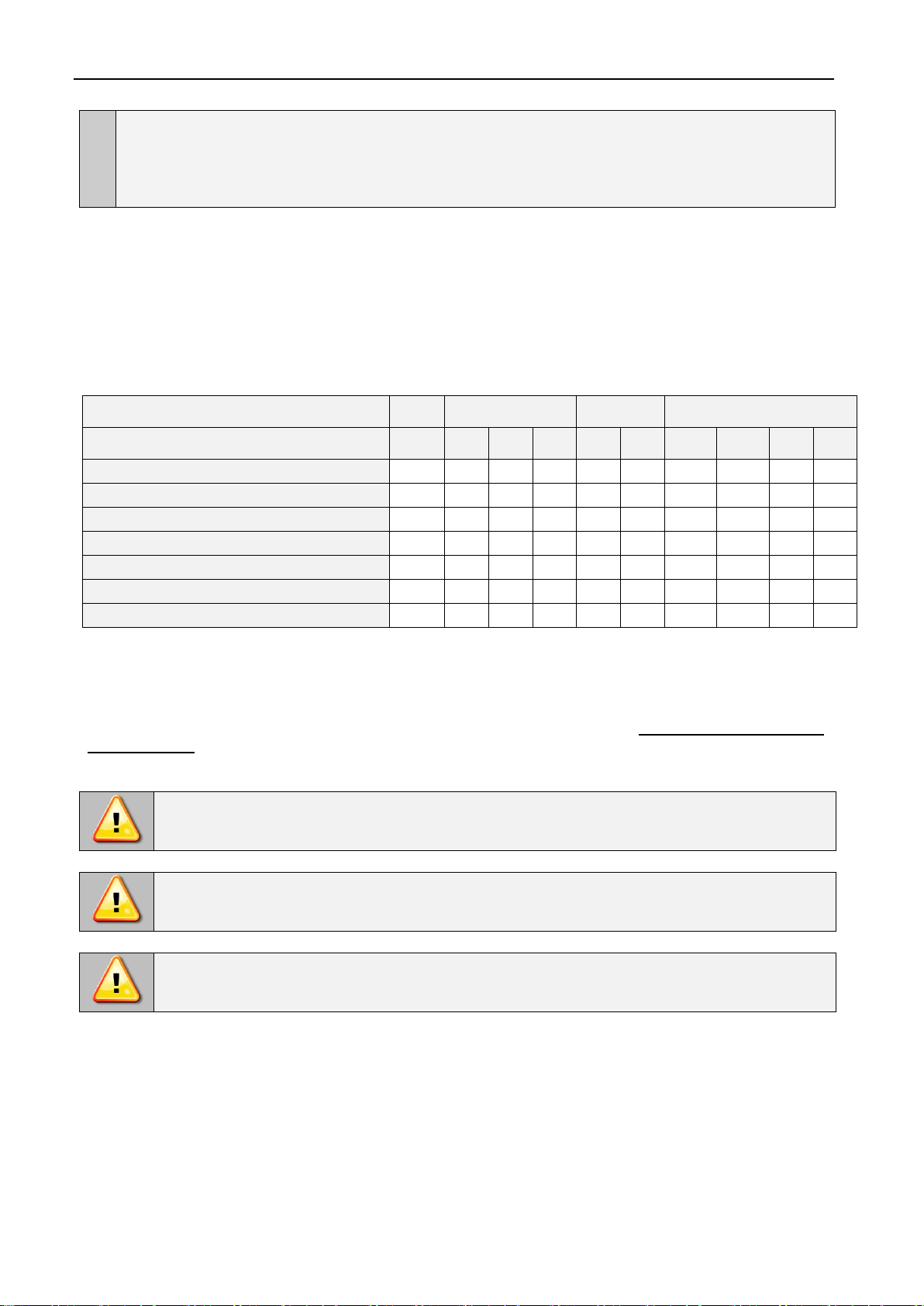
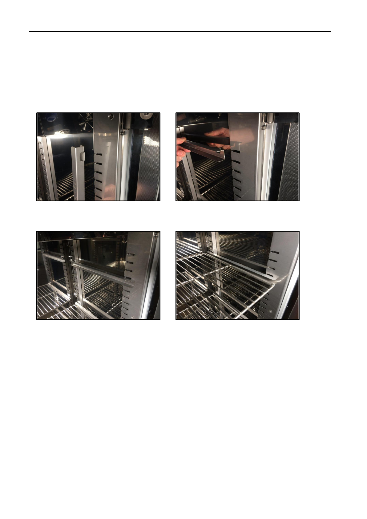
3.1. Installation of shelves .............................................................................................................................9
3.2. Remarks on the placement of samples.................................................................................................12
3.3. Closing chamber door...........................................................................................................................12
3.4. Anchoring multi-chamber equipment....................................................................................................13
4. DESCRIPTION OF THE DEVICE..................................................................................................................14
4.1. Design of ZLN 85..................................................................................................................................14
4.2. Design of ZLN-T 125, ZLN-T 200, ZLN-T 300, ZLW 200, ZLW 300 devices........................................16
4.3. Design of ZLN-UT 130 VIP, ZLN-UT 200 VIP, ZLN-UT 300 VIP, ZLN-UT 500 VIP devices.................18
5. DEVICE EQUIPMENT (standard and optional)..........................................................................................20
5.1. Internal door (standard for ZLN-UT VIP)...............................................................................................20
5.2. Door lock (standard for all units)...........................................................................................................20
5.3. Access port for external sensor (standard for all units).........................................................................20
5.4. Open door alarm (standard for all units) ...............................................................................................20
5.5. USB port (standard for all units)............................................................................................................21
5.6. Display battery backup (optionally for ZLN, ZLN-T, ZLW-T, standard for ZLN-UT VIP)........................22
5.7. Consumables........................................................................................................................................22
6. DEVICE OPERATION...................................................................................................................................22
6.1. External memory (USB flash drive).......................................................................................................23
6.2. First boot...............................................................................................................................................23
6.3. Main screen.................................................................................................................................23
6.3.1. Information panel..............................................................................................................................24
6.3.2. The meaning of icons and symbols..................................................................................................27
6.3.3. Upper menu......................................................................................................................................28
6.3.4. Alarm bar..........................................................................................................................................30
6.4. Quick Program......................................................................................................................................30
6.5. Programs.....................................................................................................................................32
6.5.1. Creating / editing a program.............................................................................................................32
6.5.2. Segments edition..............................................................................................................................33
6.5.3. Summary of segments......................................................................................................................35
6.5.4. Priority..............................................................................................................................................36
6.5.5. Loop .................................................................................................................................................37
6.5.6. Defrosting of ZLN, ZLN-T, ZLN-UT VIP devices...............................................................................37
6.6. Starting the program.............................................................................................................................37
6.6.1. The first way.....................................................................................................................................37
6.6.2. The second way...............................................................................................................................39
6.7. Quick Change of parameters................................................................................................................40
6.7.1. Quick change of set temperature .....................................................................................................40
6.7.2. Quick change of set time..................................................................................................................41

Instruction manual ZLN, ZLN-T, ZLW-T, ZLN-UT VIP SMART
4
6.8. Statistics ......................................................................................................................................42
6.9. Data record..................................................................................................................................42
6.10. Event log .....................................................................................................................................44
6.11. Info ..............................................................................................................................................46
6.12. User settings panel......................................................................................................................46
6.12.1. Unlocking the touch screen..............................................................................................................47
6.13. Time ............................................................................................................................................48
6.14. Alarms.........................................................................................................................................49
6.14.1. Alarms when set parameters are exceeded.....................................................................................49
6.14.2. Open door alarm ..............................................................................................................................50
6.14.3. STM function....................................................................................................................................51
6.14.4. Mute option.......................................................................................................................................53
6.15. Network.......................................................................................................................................53
6.16. Automatic defrosting function (standard for ZLW-T) ....................................................................54
6.17. Corrections...................................................................................................................................55
7. INTERFACE..................................................................................................................................................56
7.1. MODBUS TCP......................................................................................................................................56
8. co2back-up SYSTEM (OPTIONALLY FOR ZLN-UT VIP)...........................................................................56
8.1. Indications for using pressure cylinders................................................................................................57
8.1.1. Characteristics of carbon dioxide .....................................................................................................58
8.1.2. Hazards when working with CO2.......................................................................................58
8.1.3. Personal protection ..........................................................................................................................58
8.1.4. Control devices.................................................................................................................................59
8.1.5. First aid.............................................................................................................................................59
8.2. User's responsibility..............................................................................................................................60
8.3. Emergency shutdown of the CO2back-up system................................................................................60
8.4. Connecting the freezer to a CO2cylinder..............................................................................................60
8.5. Disconnecting the freezer from the CO2cylinder..................................................................................63
8.6. CO2Backup solenoid valve ..................................................................................................................63
8.7. Starting the device................................................................................................................................63
9. CONNECTING THE DEVICE TO A COMPUTER.........................................................................................64
10. CLEANING AND MAINTENANCE OF THE DEVICE...................................................................................64
10.1. Exterior cleaning...................................................................................................................................64
10.2. Interior cleaning....................................................................................................................................64
10.3. Cleaning the touch screen....................................................................................................................65

Instruction manual ZLN, ZLN-T, ZLW-T, ZLN-UT VIP SMART
5
11. ADVICE ON HOW TO SAFELY STORE THE DEVICE................................................................................66
12. TROUBLESHOOTING..................................................................................................................................66
12.1. Possible defects....................................................................................................................................67
13. WARRANTY CONDITIONS..........................................................................................................................67
14. RATING PLATE............................................................................................................................................68
15. TECHNICAL DATA.......................................................................................................................................69
15.1. ZLN, ZLN-T, ZLW-T devices.................................................................................................................69
15.2. ZLN-UT VIP devices.............................................................................................................................71
16. DECLARATIONS OF CONFORMITY...........................................................................................................73

Instruction manual ZLN, ZLN-T, ZLW-T, ZLN-UT VIP SMART
6
1. INTENDED USE AND IMPORTANT INFORMATION FOR THE USER
Laboratory freezers are laboratory equipment intended for freezing and storage of frozen samples below 0°C:
•laboratory freezer ZLN: -25°C … 0°C
•laboratory freezer ZLN-T: -40°C … 0°C
•laboratory freezer ZLW-T: -40°C … 0°C
•ultra-low freezer ZLN-UT VIP: -86°C...-50°C
All devices are controlled by a precise SMART controller, thanks to which the set temperature is maintained with good
fluctuation and variation. The ZLN 85 freezer is also available in a 2-chamber version with ST thermostatic cabinet or
CHL laboratory refrigerator, where each chamber is independently controlled –for service and operation of ST and
CHL devices, see the relevant instruction manual. In 2-chamber devices, the freezer is always at the bottom.
For devices with forced air convection, the symbol appears on the screen.
The meaning of information symbols
This symbol means that failure to follow the instructions could endanger people's health or life, or
damage the device. The manufacturer is not liable for damages resulting from non-compliance with
the instructions contained in the manual.
A flammable coolant is used in the cooling system. If the cooling system is damaged, ventilate the
room carefully and remove all open flames near the unit.
There are extremely low temperatures inside the chamber so do not touch the samples and the
interior of the chamber without suitable protective gloves.
This symbol indicates helpful tips.
To guarantee your security and the longevity of the unit, please comply with the following rules:
1.
The unit cannot be installed:
•outside,
•in damp places or places which can be easily flooded,
•near flammable or volatile substances,
•near acids or in corrosive environments.
2.
It is forbidden to:
•store inflammable or volatile substances inside the unit,
•touch live parts of the unit,
•operate the unit with wet hands,
•put water vessels on the unit,
•climb on the unit,
•overload the shelves (the maximum load is described in technical data),
•place objects on the bottom of the chamber.
3.
You should:
•place samples in such a way to provide proper air circulation in the chamber,
•open the door for the shortest period of time to reduce temperature fluctuations,
•secure samples from being blown out by the chamber fan e.g powdery samples,
•always check that the doors are closed correctly,
•use only mains with earth to avoid electric shocks,
•unplug the power cable holding the protective cover and not the cable itself,
•disconnect the unit from the mains before undertaking any repairs or maintenance work (in order to not

Instruction manual ZLN, ZLN-T, ZLW-T, ZLN-UT VIP SMART
7
lose the warranty during its duration, all repairs should be carried out by an authorized service),
•protect the power cable and the plug from any damage,
•disconnect the power plug before moving the unit,
•disconnect the power plug if the device will not be used for a long period of time,
•disconnect the unit and protect it from reconnecting if it has any visual fault.
Failure to comply with the above recommendations may result in damage to the device or deterioration of
technical parameters, as well as loss of warranty.
2. PACKAGE CONTENTS
ZL laboratory freezers in SMART version are delivered with:
3. BEFORE THE FIRST USE
The manufacturer sends the device protected by cardboard profiles and foil. The device should be transported in an
upright position and the package should be secured against sliding during transport.
While carrying the unit, do not tilt it to one side more than 45° from the upright position, as there is
a high probability of damaging the compressor. If it is necessary to tilt it to one side more than 45°,
then after placing it, please wait about 3 hours before connecting the unit to the mains.
After transporting the device at a temperature below 10°С, wait at least 2 hours before connecting it
to the mains.
On the surface of unit’s components made of stainless steel, slight discoloration may occur. It is a result of the
technologies used in the production of metal sheet in accordance with the requirements of PN-EN 10088-2 standard
and it is not a defect of the unit.
Device
ZLN
ZLN-T
ZLW -T
ZLN-UT VIP
Capacity
85
125
200
300
200
300
130
200
300
500
Shelves [pcs.]
2
2
2
3
2
3
1
2
2
4
Slides [pcs.]
4
4
4
6
4
6
x
x
x
x
Power cord [pcs.]
1
1
1
1
1
1
1
1
1
1
Silicone cap [pcs.]
2
2
2
2
2
2
2
2
2
2
Key for door lock [pcs.]
2
2
2
2
2
2
2
2
2
2
Wrench (13mm) for wheels adjustment [pcs.]
x
x
x
1
x
1
1
1
1
1
Quality Control Certificate [pcs.]
1
1
1
1
1
1
1
1
1
1
After receiving the device, visually assess its condition and equipment in the presence of the
person delivering the goods. A courier company is responsible for any damage caused during
transport.

Instruction manual ZLN, ZLN-T, ZLW-T, ZLN-UT VIP SMART
8
The place of installation of the unit should meet the following conditions:
•ambient temperature +10°C...+28°C,
•recommended relative humidity of the ambient air up to 60%,
•the unit has not been designed to work in highly dusty environments,
•ensure proper ventilation in the room,
•the device should be placed on a hard and stable surface,
•the unit should be placed at least 100mm away from the walls,
•the height of the room must be at least 300mm greater than the height of the unit,
•the unit is not designed to be built-in,
•the place of installation of the device should be equipped with a socket with parameters suitable for the
device.
If you don’t comply with the above recommendations, the unit may get broken or it may worsen the technical
parameters such as:
•temperature fluctuation,
•temperature variation,
•power consumption,
•icing of evaporator
and may result in loss of warranty.
Wheels / leveling feet
If the device has been equipped with wheels or leveling feet:
•in the case of wheels after placing the unit at its destination, secure the device against
movement by locking the wheels
•in the case of feet, after placing the device in the destination, they should be leveled.
If the device is equipped with wheels, they must be locked. For this purpose use the red
knob mounted in the wheel housing. At the beginning, the knob can be turned by hand,
if it encounters resistance, use a 13 size wrench.
Electric installation
Power supply of the equipment is indicated on a rating plate on the unit. Connect the device to a
socket with ground in order to avoid electric shocks in case of the unit’s failure.
The installation should be protected by a 16A slow-blow fuse and equipped with a residual current device.
Leveling wheels are ONLY for positioning the device at its destination. They can not be used to
transport the device!

Instruction manual ZLN, ZLN-T, ZLW-T, ZLN-UT VIP SMART
9
3.1. Installation of shelves
In the ZLN 85 freezer
To install the shelf or to change its position, follow these steps:
Install the shelf slide at the selected height by inserting it into proper slots on the wall of the device. Do the same with
the slide on the opposite wall.
Slide the shelf into the installed shelf slides. Now, the shelf is correctly installed!
To remove a shelf, perform the above steps in reverse order. To remove the shelf slide from the slots, lift it up and slide
it towards the rear of the chamber.

Instruction manual ZLN, ZLN-T, ZLW-T, ZLN-UT VIP SMART
10
In the ZL-T 125, ZL-T 200, ZL-T 300 models
To install the shelf or to change its position, follow these steps:
Install the shelf slide at the selected height by inserting it into proper slots on the wall of the device. Do the same with
the slide on the opposite wall.
Slide the shelf into the installed shelf slides. Now, the shelf is correctly installed!
In the freezers: ZLN-T 125, ZLN-T 200, ZLN-T 300 there are full shelves with a hole in the middle in standard
equipment.
In the freezers: ZLW-T 200 and ZLW-T 300 there are perforated shelves (as shown above) in standard equipment.
To remove a shelf, perform the above steps in reverse order.

Instruction manual ZLN, ZLN-T, ZLW-T, ZLN-UT VIP SMART
11
In the ZLN-UT 130 VIP, ZLN-UT 200 VIP, ZLN-UT 300 VIP and ZLN-UT 500 VIP models
In the ultra-low freezers ZLN-UT 200 VIP and ZLN-UT 300 VIP each separately closed compartment is equipped with a
shelf. In the ZLN-UT 500 VIP freezer, in each of the two separately closed compartments there are two shelves. In the
model ZLN-UT 130 VIP there is one compartment with one shelf.
Figure 1 Compartments in ultra-low freezers ZLN-UT 130 VIP, ZLN-UT 200 VIP, ZLN-UT 300 VIP, ZLN-UT 500 VIP
ZLN-UT 500 VIP

Instruction manual ZLN, ZLN-T, ZLW-T, ZLN-UT VIP SMART
12
3.2. Remarks on the placement of samples
To provide proper air circulation and stable conditions in which the samples are stored in the chamber, it is necessary
to keep the following rules:
•the max height of the samples should not exceed 1/3 of the space between the shelves,
•approx. 1/3 of the width and depth of the shelf should remain empty, while the distances between the
samples, as well as between the samples and the wall should be approximately equal.
The picture below is an example of the placement of samples in the chamber.
Hmax
H
Hmax
a
uv w
xy z
b
u+v+w > 1/3 a
x+y+z > 1/3 b
Hmax = 2/3H
u v w
x y z
H
≅
≅ ≅
≅
Front view
Top view
Shelf
Following the above rules will provide best optimal parameters of temperature fluctuation and variation.
3.3. Closing chamber door
Freezers door have been equipped with a gasket and open door sensor. The external door of the ZL-T and ZL-UT VIP
freezers are equipped with a lock. In ultra-low freezers each compartment is closed with a separate door.
If the door has not been closed properly, an audible and visual alarm will start. You can set delay door alarm by: 30s, 1
min, 2 min, 5 min or 10 min (see Section 6.14).

Instruction manual ZLN, ZLN-T, ZLW-T, ZLN-UT VIP SMART
13
3.4. Anchoring multi-chamber equipment
In the case of high multi-chamber units (ST/ZLN 85 or CHL/ZLN 85) they must be anchored to the wall
with suitable fixings (the anchoring kit is supplied with the device). This prevents the unit from falling over.
Lack of anchoring may result in damage to the device and in extreme cases may endanger the
health or life of the person who using the device.
Rear view
1. Install the mounting brackets (2) to the holes mar-
ked (1) on the back of the device using the sup-
plied screws and nuts. Handles can be set up or
sideways.
2. Place the equipment at the destination.
3. Use the 6 mm wall plugs adapted to the
anchoring point to attach the holders. Elongated
mounting hole in the bracket 10x10.
2
1

Instruction manual ZLN, ZLN-T, ZLW-T, ZLN-UT VIP SMART
14
4. DESCRIPTION OF THE DEVICE
SMART models are equipped with a PID microprocessor temperature controller and a 4.3 inch colour touch screen with
a resolution of 800x480.
4.1. Design of ZLN 85
Below there’s a picture of ZLN 85 model with a description of the important components of the device.
Front view
1) rating plate
2) access port ø20mm for external
sensor
3) external solid door
4) key lock
5) touch control panel
6) USB port
7) adjustable feet
1
2
4
5
6
3
7

Instruction manual ZLN, ZLN-T, ZLW-T, ZLN-UT VIP SMART
15
Rear view
1) fuse
2) main power socket C14
3) main switch
4) condenser
5) cooling system
3
4
1
2
5

Instruction manual ZLN, ZLN-T, ZLW-T, ZLN-UT VIP SMART
16
4.2. Design of ZLN-T 125, ZLN-T 200, ZLN-T 300, ZLW 200, ZLW 300 devices
Below there’s a picture of ZLN-T 200 model with a description of the important components of the device.
Front view
1) rating plate
2) handle with bolt lock with a key
3) main switch
4) wheels
5) condenser housing
6) external solid door
7) touch control panel
7
1
2
6
5
3
4

Instruction manual ZLN, ZLN-T, ZLW-T, ZLN-UT VIP SMART
17
Rear view
1) main power socket C20
2) fuse
3) balancing valve
3
2
1

Instruction manual ZLN, ZLN-T, ZLW-T, ZLN-UT VIP SMART
18
4.3. Design of ZLN-UT 130 VIP, ZLN-UT 200 VIP, ZLN-UT 300 VIP, ZLN-UT
500 VIP devices
Below there’s a picture of ZLN-UT 500 VIP model with a description of the important components of the device.
Front view
1) rating plate
2) handle with bolt lock with a key
3) main switch
4) wheels
5) condenser housing
6) emergency back-up system switch
7) external solid door
8) internal door
9) touch control panel
1
9
2
8
7
3
4
6
5

Instruction manual ZLN, ZLN-T, ZLW-T, ZLN-UT VIP SMART
19
Rear view
1) main power socket C20
2) fuse
3) potential-free alarm contact
(option)
4) CO2 back-up system (option)
5) balancing valve
5
4
3
2
1

Instruction manual ZLN, ZLN-T, ZLW-T, ZLN-UT VIP SMART
20
5. DEVICE EQUIPMENT (STANDARD AND OPTIONAL)
5.1. Internal door (standard for ZLN-UT VIP)
The interior of the ultra-low freezers ZLN-UT 130 VIP, ZLN-UT 200 VIP, ZLN-UT 300 VIP and ZLN-UT 500 VIP has
been divided into compartments, which are additionally isolated by means of the internal doors. This allows samples to
be removed without the risk of temperature rise in other compartments.
5.2. Door lock (standard for all units)
All devices have a key lock. In the model ZLN 85 the key lock is situated above the door. In the freezers ZLN-T, ZLW-T
and ZLN-UT VIP the bolt lock is located in the door handle.Two keys are supplied with the device.
5.3. Access port for external sensor (standard for all units)
A Ø20 mm access port can be used to insert an external temperature sensor for independent temperature control
inside the device. The access port has been secured with a silicone plug. The plug should cover the access port while
the unit is operating. If multiple cables have been inserted through the access port and it is not possible to use the plug,
secure the access port with adhesive tape. If you leave the access port open, it may affect temperature fluctuation and
variation inside the chamber.
5.4. Open door alarm (standard for all units)
All units have been equipped with an open door sensor. If you open the door, the icon: will appear (the number
above the icon presents open door counter. Press the icon to cancel the counter. The counter is also cancelled by
turning of the device). If the door remains open longer than the time set by the user (30s, 1 min, 2 min, 5 min, 10 min)
an acoustic signal, red pulsating alarm bar and „open door” alarm with active status will appear.
Other manuals for SMART PRO ZLN 85
1
This manual suits for next models
9
Table of contents
Popular Freezer manuals by other brands

KRAFT
KRAFT KF-HS100W user guide

Blomberg
Blomberg GEI 1110 Operating and installation instructions

Atag
Atag KD60178BFUU/A01 Instructions for use

Iceking
Iceking RZ552W.E Installation and operating manual

Zanussi
Zanussi ZFC 11JE OPERATING AND INSTALLATION Manual

Gorenje
Gorenje rk 1000 ip Instructions for use