Polaris 2882750 User manual

APPLICATION
Verify accessory fitment at Polaris.com.
BEFORE YOU BEGIN
Read these instructions and check to be sure all parts and tools are accounted for. Please retain these
installation instructions for future reference and parts ordering information.
KIT CONTENTS
This Kit includes:
REF QTY PART DESCRIPTION PART NUMBER
1 1 Head Unit 2636729
2* 8 Screw, Torx®Button Head - M4.8 X 32 -
3 1 Speaker, Left Front Dash 2636831
4 2 Harness, Speaker 2414358
51 Harness, Power and Signal 2414402
6 1 Speaker, Right Front Dash 2636832
7 1 Input, Auxiliary 2636834
8 1 Mast, Antenna, AM/FM 4014849
Instr 9927916 Rev 02 2018-07 Page 1 of 11
P/N 2882750
DASH AUDIO KIT
Instr 9927916 Rev 02 2018-07 Page 2 of 11
REF QTY PART DESCRIPTION PART NUMBER
9 1 Ground Strap, Antenna, AM/FM 4017858
10 1 Base, Antenna, AM/FM 4016695
11 1 Harness, Antenna Signal (with boot) 2411489
12 1 Nut, Hex Flange - M5 X 0.8 7547437
1 Instructions 9927916
Items marked (*) are included in Hardware Kit PN 2207078.
TOOLS REQUIRED
• Safety Glasses
• Cutting Tool
• Drill
• Drill Bit: 1/8 inch (3 mm), 3/16 inch (5 mm), 1/4 inch
(6 mm), 1/2 inch (12 mm)
• Hole Saw: 1 inch (25 mm)
• Pliers, Push Pin Rivet
• Ruler
• Screwdriver Set, Torx®
• Socket Set, Metric
• Wrench Set, Metric
IMPORTANT
Your Dash Audio Kit is exclusively designed for your vehicle. Please read the installation instructions thoroughly
before beginning. Installation is easier if the vehicle is clean and free of debris. For your safety, and to ensure a
satisfactory installation, perform all installation steps correctly in the sequence shown.
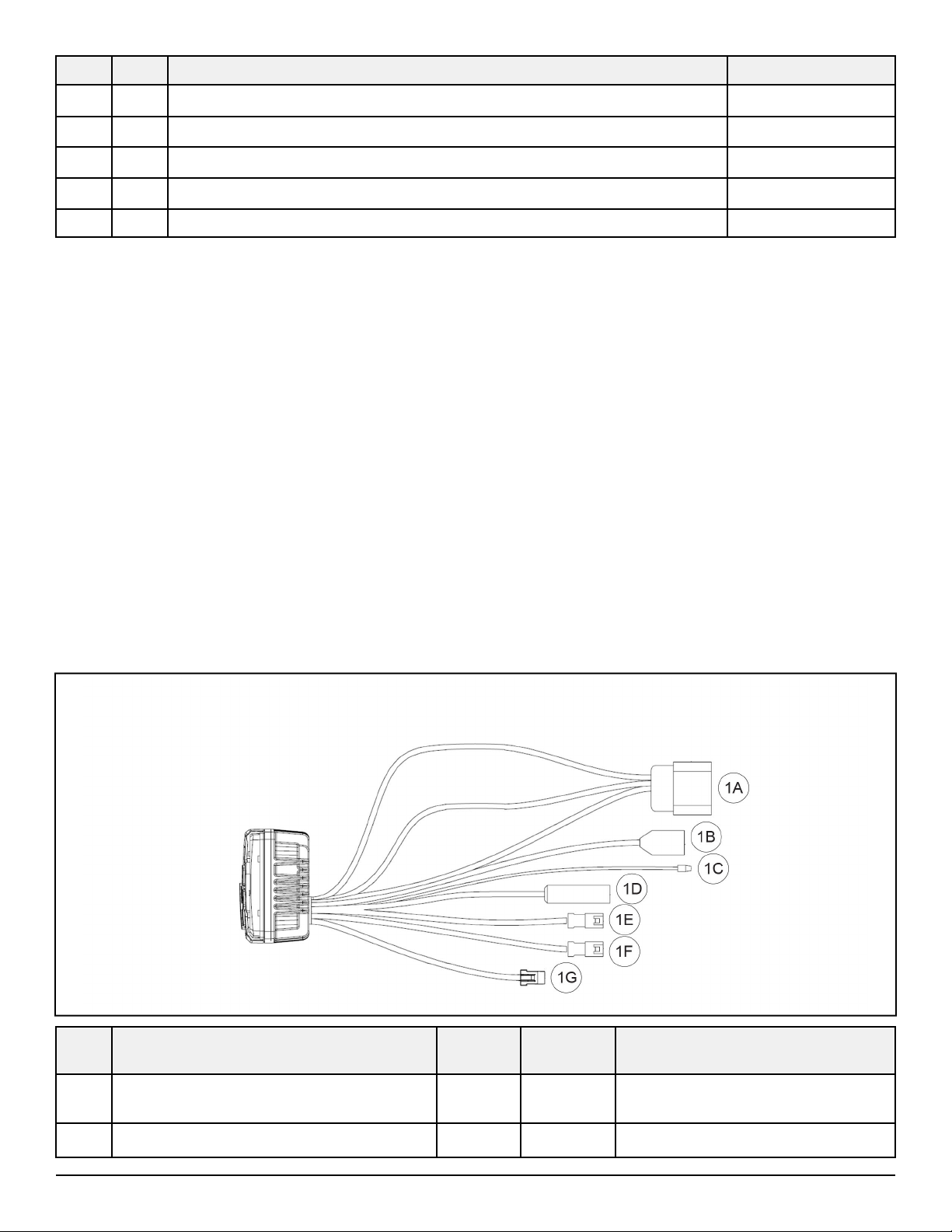
HARNESS DETAIL
HEAD UNIT qq:
REF PART DESCRIPTION WIRE
COLOR
PIN QTY/
GENDER
CONNECTS TO
1A Connector, Head Unit -12 male Power and signal harness t,
connector 5A
1B Connector, USB Black -Auxiliary input u, connector 7A

Instr 9927916 Rev 02 2018-07 Page 3 of 11
REF PART DESCRIPTION WIRE
COLOR
PIN QTY/
GENDER
CONNECTS TO
1C Connector, REMOTE ON Blue 1 male OPTIONAL: Dash Amp Kit (PN
2883408) and/or Subwoofer Kit
(PN 2882890) (each sold
separately)*
1D Connector, Antenna Signal -RF
coaxial Antenna harness s, connector
11A
1E Connector, Speaker, Front (identified as
FRONT OUT)
Black 4 male OPTIONAL: Dash Amp Kit (PN
2883408) (sold separately)
1F Connector, Speaker, Rear (identified as
REAR OUT)
Brown 4 male OPTIONAL: Subwoofer Kit (PN
2882890) (sold separately)
1G Connector, AUX 1 IN White 4 female Auxiliary input u, connector 7B
* Connecting BOTH Dash Amp Kit AND Subwoofer Kit requires remote splitter harness, included in Dash Amp
Kit.
SPEAKER HARNESS rr:
REF PART DESCRIPTION WIRE
COLOR
PIN QTY/
GENDER
CONNECTS TO
4A Connector, Power and Signal Harness -2 male Power and signal harness t,
connectors 5E and 5H
4B Clip, Edge - - Vehicle structure
4C Grommet - - Vehicle structure
4D Terminal, Spade (3/16 inch), Speaker White -Speaker eor y, positive (+)
terminal
4E Terminal, Spade (1/8 inch), Speaker Black -Speaker eor y, negative (–)
terminal

Instr 9927916 Rev 02 2018-07 Page 4 of 11
POWER AND SIGNAL HARNESS tt:
REF PART DESCRIPTION WIRE
COLOR
PIN QTY/
GENDER
CONNECTS TO
5A Connector, Head Unit -12 female Head unit q, connector 1A
5B Clip, Edge - - Vehicle structure
5C Connector, Speaker, Right Rear
(identified as RH SPEAKER; taped to
breakout; with cap)
-2 female
OPTIONAL: Rear Roof Speaker Kit
(PN 2882876) or Door Speaker Kit
(PN 2882889)*
5D Connector, Speaker, Left Rear (identified
as LH SPEAKER; taped to breakout;
with cap)
-2 female
5E Connector, Speaker, Left Front (identified
as LH SPEAKER)
-2 female Speaker harness r, connector 4A
5F Relay/Fuse Block - - Vehicle structure
5G Connector, Terminal Block -3 female Vehicle terminal block
5H Connector, Speaker, Right Front
(identified as RH SPEAKER)
-2 female Speaker harness r, connector 4A
* Or compatible kit.

Instr 9927916 Rev 02 2018-07 Page 5 of 11
AUXILIARY INPUT uu:
REF PART DESCRIPTION WIRE
COLOR
PIN QTY/
GENDER
CONNECTS TO
7A Connector, USB - - Head unit q, connector 1B
7B Connector, 3.5 mm Stereo -4 male Head unit q, connector 1G
ANTENNA HARNESS ss:
REF PART DESCRIPTION WIRE
COLOR
PIN QTY/
GENDER
CONNECTS TO
11A Connector, Antenna Signal -RF
coaxial Head unit q, connector 1D
11B Connector, Antenna Base (with boot) -FIAMM Antenna base a

Instr 9927916 Rev 02 2018-07 Page 6 of 11
INSTALLATION INSTRUCTIONS
1. Shift vehicle transmission into “PARK”. Turn
ignition switch to “OFF” position and remove key.
WARNING
Ensure red positive (+) battery terminal is
COMPLETELY COVERED by protective boot.
Accidental tool contact across both battery terminals
will result in high current electrical arc, and may
result in battery explosion. Death or serious personal
injury may occur.
2. Flip up passenger seat bottom (CREW: right rear
passenger seat bottom) and remove underseat
storage compartment. Disconnect black negative
(-) cable from battery.
3. Gain access.
a. Remove hood.
b. If windshield is installed, then open it or remove
it as required to gain access to upper dash.
c. Remove upper dash cupholder by removing
two push pin rivets A, then sliding cupholder
rearward. Retain rivets. Cupholder will not be
reused.
d. Tilt steering wheel to full down position. Detach
instrument cluster hood by removing two push
pin rivets B, then slide hood (with instrument
cluster) rearward. Disconnect instrument
cluster wiring harness. Retain rivets.
e. Open door to upper storage compartment.
Remove four screws Cfrom forward wall of
compartment, then remove compartment/door
assembly from dash. Retain screws.
f. Remove upper dash.
i. Remove six push pin rivets Dalong
forward edge of dash.

Instr 9927916 Rev 02 2018-07 Page 7 of 11
ii. Remove five push pin rivets Efrom LH side
of dash: two at center cupholder, two at
instrument cluster, and one on underside of
dash above cupholder.
iii. Remove three push pin rivets Ffrom RH
side of dash: two inside upper storage area
and one on underside of dash above
cupholder.
iv. Remove upper dash from vehicle and set
aside.
NOTE
HVAC vehicles: Either cut cable ties securing ducts
to vents, or leave cable ties intact and partially lift
upper dash to gain access for audio installation.
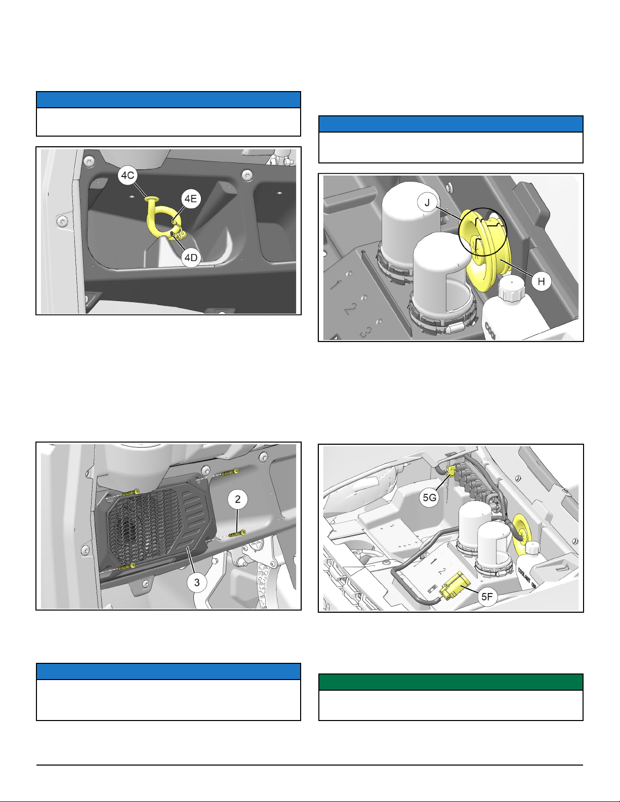
4. Install speakers and speaker harnesses.
a. Using 1/8 inch (3 mm) drill bit, drill out four
fastener dimples G. Only drill deep enough to
penetrate panel surface and enter pre-drilled
bosses on opposite side of panel.
NOTE
All holes drilled from rear (passenger) side of panel.
Forward side shown below for reference only.
Instr 9927916 Rev 02 2018-07 Page 8 of 11
b. Reaching down through upper dash cavity,
route spade terminals 4D and 4E on speaker
harness rdown through hole in speaker
compartment, then secure grommet 4C in hole.
NOTE
See previous section, HARNESS DETAIL, for
connector identification.
c. Join speaker harness rto speaker e:
i. Connector 4E (1/8 inch spade, BLACK
wire) to negative (–) terminal on speaker
ii. Connector 4D (3/16 inch spade, WHITE
wire) to positive (+) terminal on speaker
d. Install LH speaker einto speaker
compartment using four screws w. Do not
overtighten screws.
e. Repeat Steps 4a. through d. for RH side using
speaker y.
5. Install head unit harness.
NOTE
See previous section, HARNESS DETAIL, as well
as head unit operating instructions for connector
identification.
a. Detach firewall grommet Hfrom firewall by
pulling forward slightly. Cut grommet radially
from center of hole upwards, completely
through grommet wall, as shown in J. Use
care to ensure any existing wire harness
passing through grommet is not damaged.
NOTE
Purpose of cutting grommet is to enable power and
signal harness tto pass through grommet.
b. Route all harness components EXCEPT relay/
fuse block 5F and terminal block connector 5G
from under-hood compartment rearward
through firewall grommet Hinto upper dash
compartment.
Reinstall firewall grommet into firewall with cut
oriented at 12 o’clock position.
c. Drill out one accessory plug (1/4 inch / 6 mm)
on under-hood liner, just forward of air intake
ducts, then install relay/fuse block 5F using
attached fir tree clip.
IMPORTANT
Control drill depth to prevent damage to underlying
structure or components.
d. Open power cap on vehicle terminal block at
any open location, then plug in connector 5G.
Instr 9927916 Rev 02 2018-07 Page 9 of 11
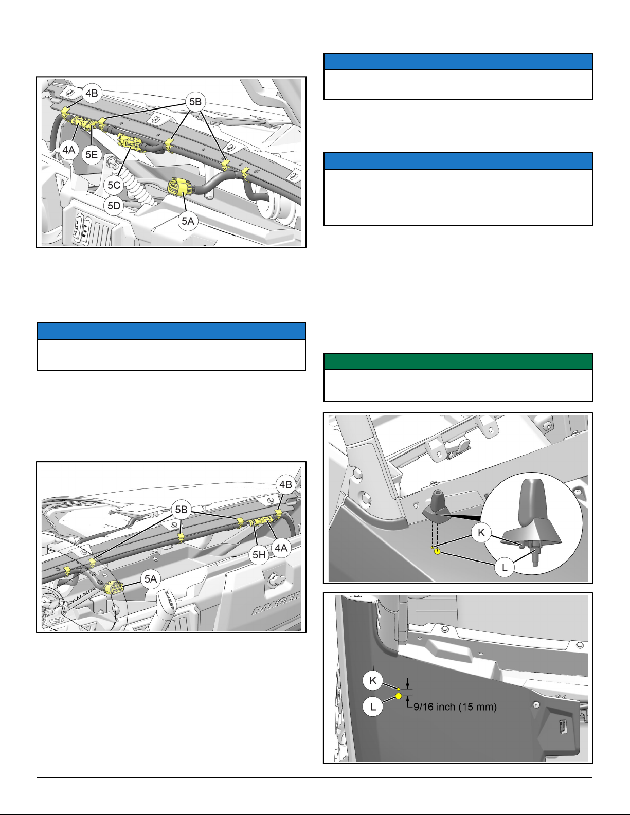
e. On LH side of harness tjoin front speaker
connector 5E to speaker harness connector 4A
on harness r.
f. OPTIONAL: If Rear Speaker Kit (PN 2882876)
or Door Speaker Kit (PN 2882889) is installed,
then remove caps from connectors 5C and 5D
on harness tand join to corresponding rear or
door speaker connectors.
NOTE
Connectors 5C and 5D are taped to harness
breakout from factory.
g. Secure both harnesses rand tto lower LH
leg of front dash bracket using one edge clip
4B and three edge clips 5B.
h. On RH side of harness tjoin front speaker
connector 5H to speaker harness connector 4A
on harness r.
i. Secure both harnesses rand tto lower RH
leg of front dash bracket using one edge clip
4B and three edge clips 5B.
6. Install AM/FM antenna.
NOTE
See previous section, HARNESS DETAIL, for
connector identification.
a. Mark two holes on top of right front fender for
alignment pin Kand antenna mounting post
L, both located on antenna base a.
NOTE
Exact base location is not critical. However, if mast
tilt functionality is desired, ensure location allows
desired tilt, and that ground strap ocan reach
chassis ground location. See Step c. below.
Mark center of alignment pin hole K9/16 inch
(15 mm) REARWARD from center of mounting
post hole Las shown, then drill holes at
marked locations:
• 3/16 inch (5 mm) diameter hole for alignment
pin K
• 1/2 inch (12 mm) diameter hole for mounting
post L
IMPORTANT
Control drill depth to prevent damage to underlying
structure or components.
Instr 9927916 Rev 02 2018-07 Page 10 of 11
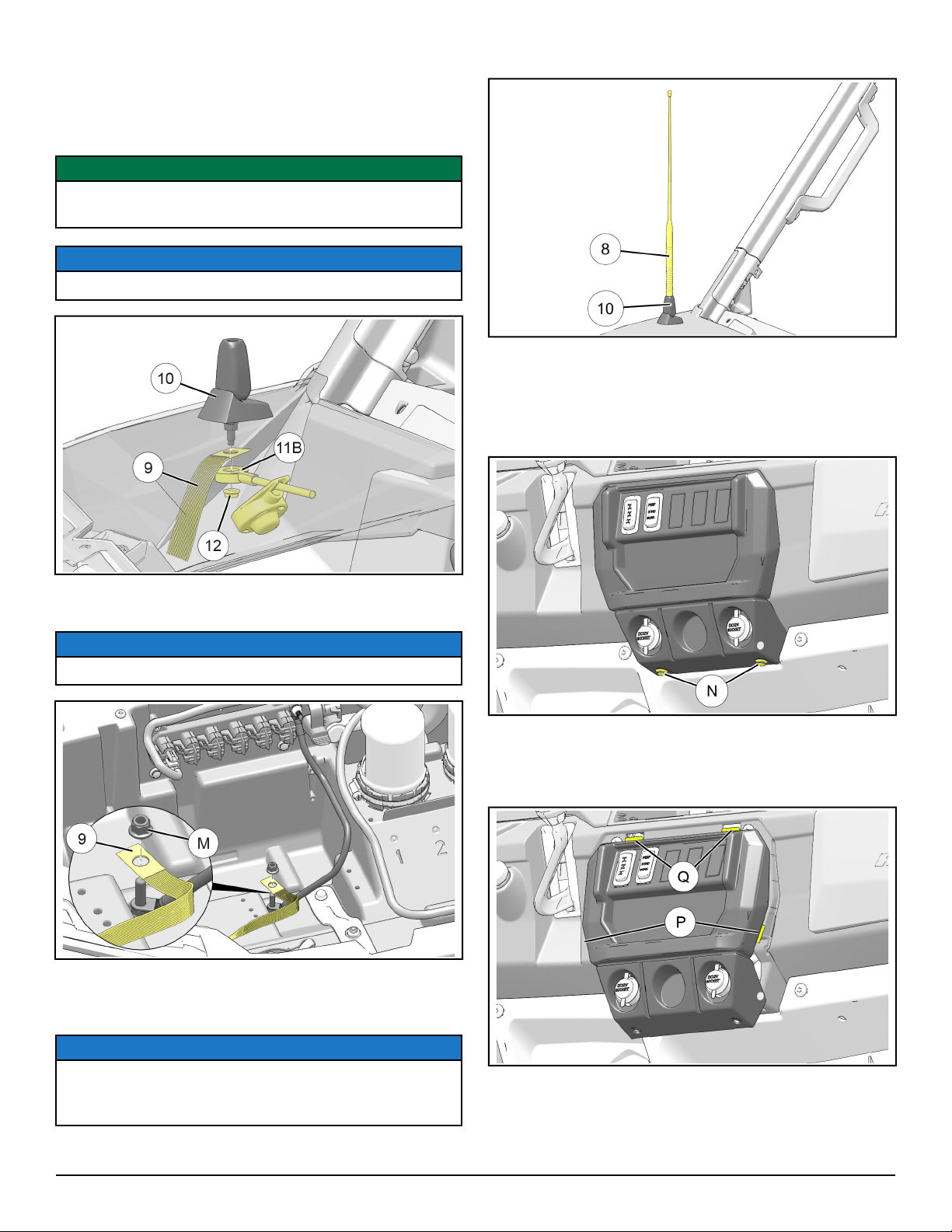
b. Insert threaded post and alignment pin located
on antenna base athrough drilled holes in
fender, attach one end of ground strap oand
connector 11B on antenna harness s, then
secure with STEEL nut d. Install rubber boot.
IMPORTANT
Do NOT remove NYLON nut pre-installed to
threaded post.
NOTE
Fender shown partially transparent for clarity.
c. Remove nut Mfrom ground stud, install loose
end of ground strap o, then reinstall nut.
NOTE
Ground strap improves AM reception.
d. Route connector 11A on antenna harness s
rearward through firewall grommet Hinto
upper dash compartment.
NOTE
Antenna will be connected to head unit in Step 9.
Coil and stow excess antenna harness length in
upper dash compartment.
e. Thread antenna mast iinto antenna base a.
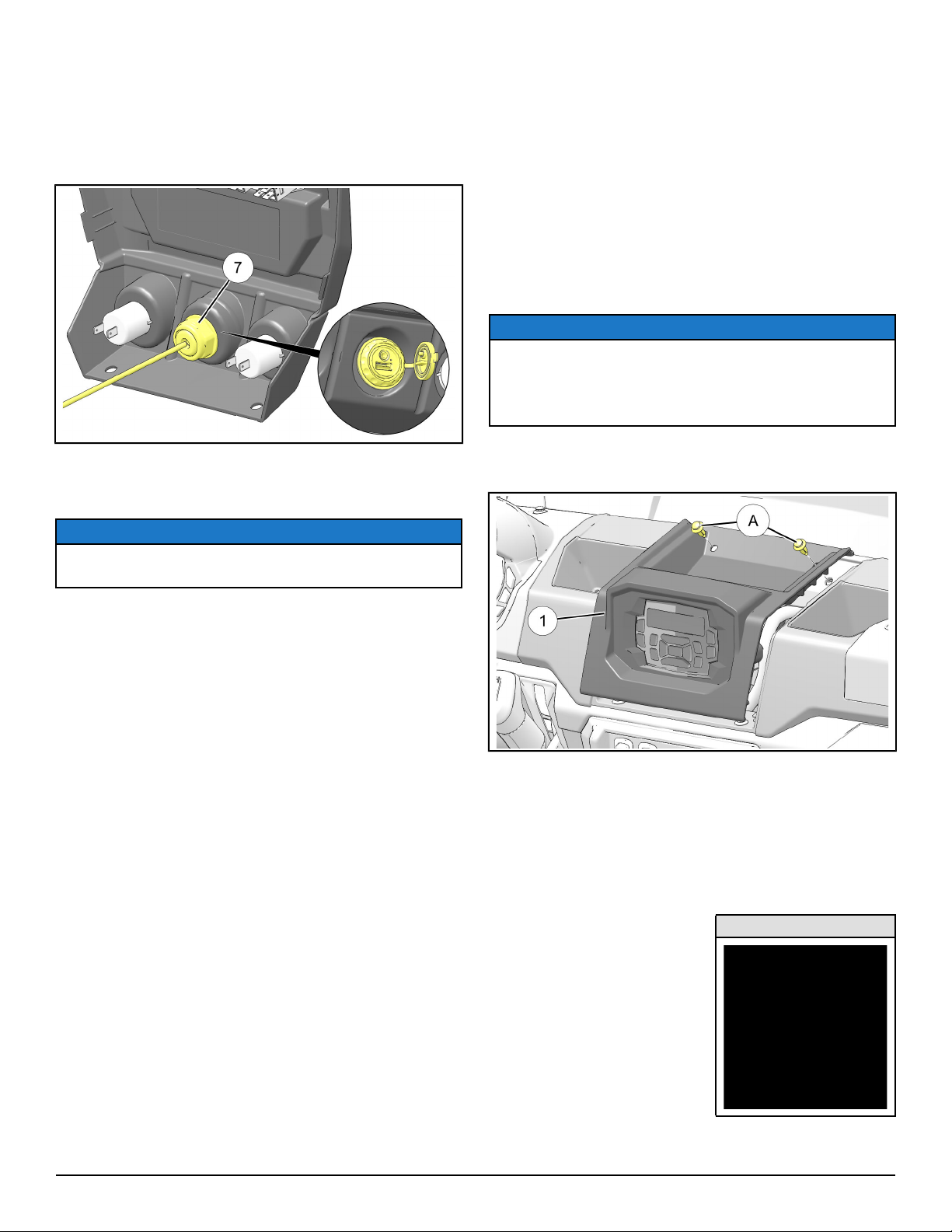
7. OPTIONAL: Install auxiliary input.
a. Gain access.
i. Remove two push pin rivets Nfrom lower
face of control panel. Retain rivets.
ii. Rotate bottom of control panel rearward,
disengaging two side tabs P
, then drop two
upper tabs Qout of slots in main dash
panel.
iii. Label and disconnect electrical harnesses
from switches, sockets, or other devices in
control panel.
Instr 9927916 Rev 02 2018-07 Page 11 of 11
b. Using 1 inch diameter hole saw, drill through
lower center cavity for installation of auxiliary
input u.
Remove nut and rubber gasket from auxiliary
input u, route wires rearward through opening,
then reinstall gasket and nut.
c. Reconnect electrical harnesses disconnected
in Step a. above, then reinstall control panel
using two retained rivets N.
NOTE
Auxiliary input will be connected to head unit in Step
9.
8. Reinstall all access EXCEPT upper dash
cupholder. See Step 3.
9. Hold head unit qnear upper dash cutout and
make the following connections:
a. Join connector 5A on harness tto head unit
connector 1A.
b. Join connector 11A on antenna harness sto
head unit connector 1D.
c. Join connector 7A on auxiliary input uto head
unit connector 1B.
d. Join connector 7B on auxiliary input uto head
unit connector 1G.
e. OPTIONAL: Join dash amp AUDIO SOURCE
(signal) connector to head unit FRONT OUT
connector 1E.
f. OPTIONAL: Join subwoofer AUDIO SOURCE
connector to head unit REAR OUT connector
1F.
g. OPTIONAL: Join subwoofer AMP ON
connector OR dash amp AUDIO SOURCE
(remote) connector to head unit REMOTE ON
connector 1C.
NOTE
Joining BOTH subwoofer AND dash amp to head
unit requires remote splitter harness (included with
Dash Amp Kit; see Dash Amp Kit instructions for
detail).
10.Install head unit (with bezel) into upper dash
cutout using two retained push pin rivets A.
11. Reconnect black negative (-) cable to battery, then
reinstall under-seat storage compartment and
driver’s seat.
FEEDBACK FORM
A feedback form has been created for the installer to provide any comments, questions
or concerns about the installation instructions. The form is viewable on mobile devices
by scanning the QR code or by clicking HERE if viewing on a PC.
FEEDBACK FORM
Table of contents
Other Polaris Car Stereo System manuals


