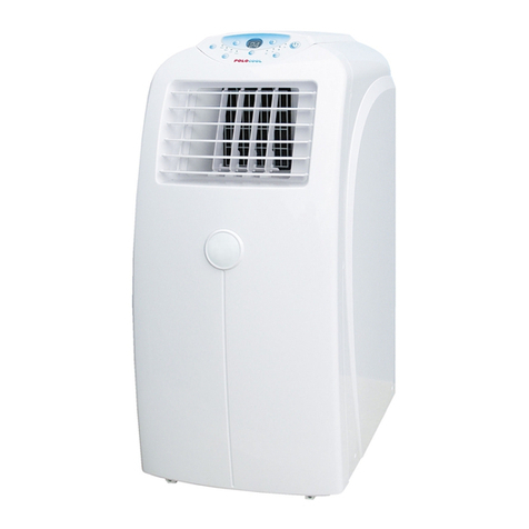
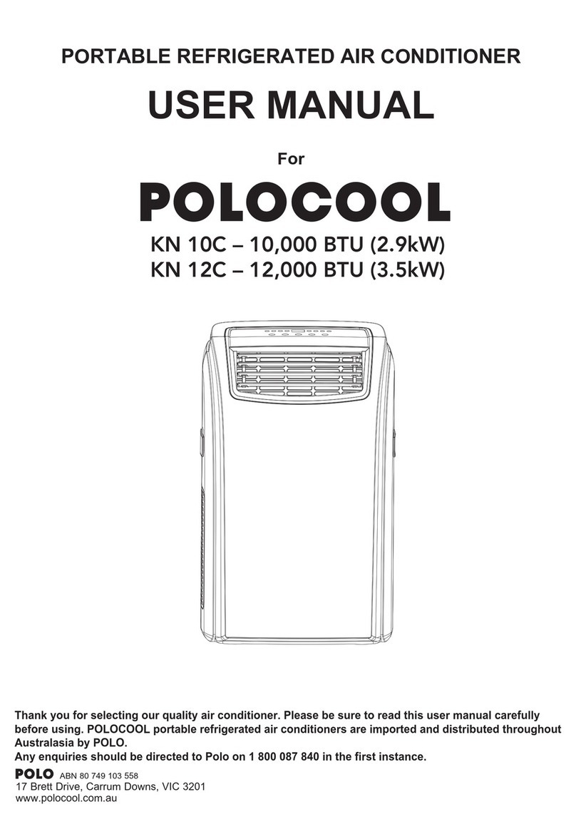
Polocool PQ10 User manual

Thank you for selecting our quality air conditioner. Please be sure to read this user manual carefully before using.
POLOCOOL Portable Refrigerated Air Conditioners are imported and distributed throughout Australasia by POLO
Appliances. Any enquiries should be directed to POLO Appliances on 1800 087 840 in the rst instance
PORTABLE REFRIGERATED AIR CONDITIONER
USER MANUAL
For
Whisper
PQ10 10,000 BTU (2.9kW)
AUGUST 2017
POLOCOOL
POLOCOOL
Appliances
ABN 80 749 103 558
17 Brett Drive, Carrum Downs, VIC 3201
www.mypolo.com.au

1
Important Issues Regarding the Proper
Use of this Air Conditioner
Please contact Polo on 1 800 087 840
for advice before returning unit
Use this air conditioner only as described in this instruction manual.
• This appliance is fitted with a special safety device. When the compressor switches off or when the
appliance is first turned on, this device prevents the compressor from switching on again for at least
three minutes.
• This air conditioner has been designed and manufactured to operate in a domestic situation only
and should not be used for other purposes.
• The appliance is not intended for use by persons (including children) with reduced physical,
sensory or mental capabilities, or lack of experience and knowledge, unless they have been given
supervision or instruction concerning use of the appliance by a person responsible for their safety.
Children should be supervised to ensure they don’t play with the appliance.
• Never use the air conditioner in damp rooms (eg bathrooms and laundries).
• If the power cord is damaged, it must be replaced with a new cord installed by a suitably qualified
person or POLO serviceman.
• This air conditioner is designed to be connected to a standard 10 amp power supply outlet.
• Do not pull on or place strain on the power cord when using the appliance.
• Do not operate or stop the appliance by inserting or pulling out the power plug. Use the on/off
switch on the air conditioner control panel or the remote control.
• Do not connect to multiple power outlets on extension leads.
• Do not rest hot or heavy objects on the appliance.
• Always unplug the unit from the power outlet before cleaning or maintenance operations, for
example filter cleaning.
• Do not place the air conditioner or plastic window slider in direct sunlight.
• For maximum cooling efficiency keep the exhaust hose as short and as free of bends as possible.
• Clean the filters at least once every two weeks.
• Do not splash the unit with water.
• Do not move the unit by pulling the exhaust hose attached to the back of the unit.
• Do not move air conditioner when it is operating.
• Do not use the unit with the air intake and outlet grills closed, covered or obstructed.
• Before transporting drain the water tray in accordance with the instructions on page 15. After
transportation, wait at least one hour before switching the unit on.
•
The unit should be transported in a vertical position. If this is not possible, secure the unit at an
angle, do not lay it horizontally. After transporting, wait at least one hour before switching the unit on.
• Do not operate the air conditioner outdoors or in areas open to the outdoors.
• If the air conditioner is correctly set and runs without cool air coming out of the front air outlet after
10 minutes of correct operation, switch off the unit and contact POLO immediately.
• When cool air is coming out of the top air outlet, hot air should always be expelled from the bottom
rear outlet. If it is not, switch off and contact POLO immediately.
THIS PRODUCT IS FOR HOUSEHOLD USE ONLY
RETAIN THIS MANUAL FOR FUTURE REFERENCE

CONTENTS
Introduction........................................................................................ 3
Description of each part and function................................................ 4
Installation.......................................................................................... 5
Description of the control panel......................................................... 7
Operating from the control panel....................................................... 8
Description of the remote control ...................................................... 9
Operating from the remote control .................................................... 10
Water drainage methods..................................................................... 15
Maintenance and service.................................................................... 16
Trouble shooting ................................................................................ 17
2

3
INTRODUCTION
This portable air conditioner can alter the room temperature and humidity. It has multiple functions of cooling dehumidifying
(drying) and fan ventilation, and can be moved from room to room and transported from building to building easily. In addition,
the desired humidity level can be set between 35-85%.
The air conditioner can maintain set room indoor air temperatures between 17°C and 30°C. The set room temperature is
displayed on the remote control and in the control panel on the unit. This does not mean that the air conditioner will necessarily
reduce the actual room temperature to the set room temperature. This appliance operates at half the noise levels of most other
portable air conditioners and is ideal for bedrooms.
GUIDELINES FOR OPTIMISING COOLING EFFECTIVENESS
This POLOCOOL “Whisper” portable refrigerated air conditioner model PQ10 has a maximum cooling capacity of
10,000 BTU or 2.9kW.
This is sufcient to cool rooms with a oor area of between 5 and 18 square metres
• Do not place the air conditioner or plastic window slider in direct sunlight. Close all curtains in the room being cooled.
•
For maximum cooling (COOLING MODE), set the temperature at 18°C and the fan at HIGH. After approximately
3 minutes, the compressor will turn on and cooled air will come out of the front air outlet. Warm air will also come out of
the rear outlet and into the exhaust hose.
•
In COOLING MODE the air conditioner will not cool unless the set temperature is below the existing room temperature.
• In COOLING MODE once the existing room temperature reaches the set temperature, the fan continues operating and
the compressor switches on and off to maintain the set temperature within the room.
• For maximum cooling output keep the exhaust hose as short and as straight as possible. Minimise bends which can
reduce the maximum cooling capacity of the air conditioner. Elevate the air conditioner if necessary.
• Make sure the air intake and outlet grills are unobstructed.
• Clean the lters at least once every two weeks.

4
DESCRIPTION OF EACH PART AND FUNCTION
rearfront
control panel
handle
(both sides)
horizontal louvre blade
Castor
power plug socket
power cord buckle
bottom tray drain outlet
power cord outlet
upper air filter
(behind the grille)
upper air intake
air outlet
lower air filter
lower air intake
drain outlet
1
2
3
4
5
6
8
7
9
10
13
12
11
14
rearfront
control panel
handle
(both sides)
horizontal louvre blade
Castor
power plug socket
power cord buckle
bottom tray drain outlet
power cord outlet
upper air filter
(behind the grille)
upper air intake
air outlet
lower air filter
lower air intake
drain outlet
1
2
3
4
5
6
8
7
9
10
13
12
11
14
1. Control Panel
Controls the functions of the air
conditioner
2. Horizontal Louvre Blade
This lifts up automatically when air
conditioner turned on and cooled air
comes out of this outlet. It retracts
closed when air conditioner is
turned off.
3. Handles
Used when moving the air
conditioner
4. Castors
Enables the air conditioner to be
easily moved
5. Upper Air Filter (behind the grille)
Filters air entering the evaporator
6. Upper Air Intake
Enables room air to enter the
evaporator
7. Middle Drain Outlet
Enables water to be continuously
drained using the drain hose.
Only used when the unit is in
dehumidiying mode.
8. Air Outlet
Exhaust hose is connected here to
discharge air
9. Lower Air Filter
Filters air entering the condenser
10. Lower Air Intake
Air intake to condenser
11. Power Plug Socket
Used to store power plug after cord
wound onto power cord winder
bracket
12. Power Cord Buckle
Recess for power cord winder bracket
13. Power Cord Outlet
Power cord leaving unit
14. Bottom Water Tank/Tray
Drain Outlet
Remove cap and plug to drain water
from water tank/tray drain outlet
15. Window Slider
Fits in window and hose outlet is
attached
16. Hose Outlet
Connects to window slider and is
pushed onto the end of the exhaust
hose
17. Hose Inlet
Connects exhaust hose to rear of
unit and is pushed onto the end of
the exhaust hose
18. Exhaust Hose
Approx 1.45m long fully extended
19. Remote Control
20. Power cord winder bracket
Pushes into power cord buckle.
Store power cord by winding around
this bracket
21. Drain Hose
Used to drain water from middle/
bottom drain outlets
22. Bolt
Installed in hole in window slider to
fix adjusted length
23. Foam Seal A (Adhesive)
Used to seal around window slider
if required
24. Foam Seal B (Adhesive)
Used to seal around window slider
if required
25. Foam Seal C (Non Adhesive)
Used to seal gap in top of open
sash windows
26. Security Bracket & 2 screws
Used to secure windows/doors
& stop them being opened after
window slider installed
15
1716
18 20
22 23
24
25
26
21
19
front rear
Bolt
Foam Seal A (Adhesive)
Foam Seal B (Adhesive)
Foam Seal C (Non-adhesive)
Security Bracket and 2 Screws
Bolt
Foam Seal A (Adhesive)
Foam Seal B (Adhesive)
Foam Seal C (Non-adhesive)
Security Bracket and 2 Screws
Bolt
Foam Seal A (Adhesive)
Foam Seal B (Adhesive)
Foam Seal C (Non-adhesive)
Security Bracket and 2 Screws
Bolt
Foam Seal A (Adhesive)
Foam Seal B (Adhesive)
Foam Seal C (Non-adhesive)
Security Bracket and 2 Screws
Bolt
Foam Seal A (Adhesive)
Foam Seal B (Adhesive)
Foam Seal C (Non-adhesive)
Security Bracket and 2 Screws

5
INSTALLATION
SELECTION OF INSTALLATION LOCATION (Fig.3)
Place the portable air conditioner in a at location where the air inlets
and outlets cannot be covered up. Place the unit no less than 50cm away
from a wall or other obstacle. In addition a minimum 50cm clearance is
required from all faces of the air conditioner including the rear face.
hose
outlet hose
hose
inlet
ASSEMBLY OF EXHAUST HOSE, HOSE INLET, HOSE OUTLET AND WINDOW SLIDER
(a) Press one end of the exhaust hose into the hose outlet which automatically clamps by the three plastic buckles. Lift
buckles to remove.
(b) Press the other end of the exhaust hose into the hose inlet which automatically clamps by the three plastic buckles.
Lift buckles to remove.
(c) Install the hose outlet into the window slider by lining up the 4 plastic buckles with the cutouts in the window slider
Ensure the 4 plastic buckles are pushed all the way into the window slider to ensure a rm t. Press buckles to
remove from window slider.
(d) Install the hose inlet into the appliance by pushing into the lower groove of the air outlet
on the unit while the hook on the hose inlet is aligned with the hole seat of the air outlet.
Lift hose inlet upwards to remove. See sketches on right.
(e) When mounting try and keep the air exhaust hose horizontal and do not extend its length
by attaching it to another hose as this reduces the cooling capacity of the appliance.
(f) Place the hose outlet to the nearest window. The length of the air exhaust hose is between
330mm-1450mm approx. Use the minium length when working and keep it as straight as
possible.
Fig. 3
50cm clearance
at back to
allow for air
outlet hose.
50cm clearance
required for
air inlet.
50cm
50cm
50cm
window
slider
use bolt to fasten 2 parts of the
window slider once they are
adjusted to the proper length
Installation of hose inlet
into appliance

6
WINDOW SLIDER KIT INSTALLATION (Fig. 9, Fig. 10, Fig. 11 and Fig. 12)
The window slider kit has been designed to fit most standard "vertical" and "horizontal" window applications. It may
be necessary for you to improvise/modify some aspects of the installation procedures for certain types of
windows. Some window types may require the use of cardboard fillers and/or duct tape to install.
Please refer to illustration for minimum and maximum window openings.
Min. 67.5 cm
Max. 123 cm (to last securing hole) Min. 67.5 cm
Max. 123 cm (to last securing hole)
Min. 50cm
Max. 96.5cm Max. 96.5cm
Additional complete window kits may be purchased from POLO to enable pre-installation in windows in other rooms.
Window slider length
Gaps can be sealed using
cardboard or plastic and duct tape.
Window (Door) slider height
Standard door height 210cm.
Gap can be sealed using
cardboard and duct tape.
Additional window sliders
can also be purchased to fill
this gap.
WINDOW SLIDER INSTALLATION
The window slider has been designed to t most standard “vertical” and “horizontal” window applications. It may be
necessary for you to improvise/modify some aspects of the installation procedures for certain types of windows. Some
window types may require the use of cardboard or plastic llers and/or duct tape to install. Additional complete window
kits may be purchased from POLO to enable pre-installation in windows in other rooms. Window sliders may be cut to length
to t different size windows.
Please refer to illustration for minimum and maximum window openings.
Hose inlet must be right way
around to ensure window is
hard up against slider
Gaps can be sealed using cardboard or
plastic and duct tape or foam seals.
Min. 67.5cm
Max. 123cm Max. 123cm

7
DESCRIPTION OF THE CONTROL PANEL
Operation
10
Swing button
Sleep(Eco)/Filter button
Fan/Ion button(Ion is optional)
Used to initiate the Auto swing feature. When the
operation is ON, press the SWING button can stop
the louver at the desired angle.
Used to initiate the SLEEP/ECO operation.
NOTE: After 250 hours of operation, the filter
indicator light illuminates. This feature is a
reminder to clean the Air Filter for more efficient
Timer button
Used to initiate the AUTO ON start time and AUTO
OFF stop time program, in conjuction with the + & -
buttons. The timer on/off indicator light illuminates
under the timer on/off settings.
Control the fan speed. Press to select the fan speed
in four steps-LOW, MED(optional), HIGH and AUTO.
The fan speed indicator light illuminates
under
different fan settings except AUTO speed. When
select AUTO fan speed, all the fan indicator lights
turn dark.
NOTE: Press this button for 3 seconds to initiate ION
feature. The ion generator is energized and will help
to remove pollen and impurities from the air, and trap
them in the filter. Press it for 3 seconds again to stop
the ION feature.
SWING button
Used to initiate the Auto swing feature. When the operation is ON, press the SWING button can stop the louver at the desired
angle.
FAN BUTTON
Control the fan speed. Press to select the fan speed in three steps - LOW, HIGH and AUTO. The fan speed indicator light
illuminates under different fan settings except AUTO speed. When select AUTO fan speed, all the fan indicator lights turn dark.
TIMER button
Used to initiate the AUTO ON start time and AUTO OFF stop time program, in conjunction with the + & - buttons. The timer on/
off indicator light illuminates under the timer on/off settings.
SLEEP(ECO)/FILTER button
Used to initiate the SLEEP/ECO operation. NOTE: After 250 hours of operation, the lter indicator light illuminates . This
feature is a reminder to clean the Air Filter for more efcient operation. Press this button for 3 seconds to cancel the reminder.
MODE button
Selects the appropriate operating mode. Each time you press the button, a mode is selected in a sequence that goes from
Operation
10
Swing button
Sleep(Eco)/Filter button
Fan/Ion button(Ion is optional)
Used to initiate the Auto swing feature. When the
operation is ON, press the SWING button can stop
the louver at the desired angle.
Used to initiate the SLEEP/ECO operation.
NOTE: After 250 hours of operation, the filter
indicator light illuminates. This feature is a
reminder to clean the Air Filter for more efficient
Timer button
Used to initiate the AUTO ON start time and AUTO
OFF stop time program, in conjuction with the + & -
buttons. The timer on/off indicator light illuminates
under the timer on/off settings.
Control the fan speed. Press to select the fan speed
in four steps-LOW, MED(optional), HIGH and AUTO.
The fan speed indicator light illuminates
under
different fan settings except AUTO speed. When
select AUTO fan speed, all the fan indicator lights
turn dark.
NOTE: Press this button for 3 seconds to initiate ION
feature. The ion generator is energized and will help
to remove pollen and impurities from the air, and trap
them in the filter. Press it for 3 seconds again to stop
the ION feature.
COOL,
Operation
10
Swing button
Sleep(Eco)/Filter button
Fan/Ion button(Ion is optional)
Used to initiate the Auto swing feature. When the
operation is ON, press the SWING button can stop
the louver at the desired angle.
Used to initiate the SLEEP/ECO operation.
NOTE: After 250 hours of operation, the filter
indicator light illuminates. This feature is a
reminder to clean the Air Filter for more efficient
Timer button
Used to initiate the AUTO ON start time and AUTO
OFF stop time program, in conjuction with the + & -
buttons. The timer on/off indicator light illuminates
under the timer on/off settings.
Control the fan speed. Press to select the fan speed
in four steps-LOW, MED(optional), HIGH and AUTO.
The fan speed indicator light illuminates
under
different fan settings except AUTO speed. When
select AUTO fan speed, all the fan indicator lights
turn dark.
NOTE: Press this button for 3 seconds to initiate ION
feature. The ion generator is energized and will help
to remove pollen and impurities from the air, and trap
them in the filter. Press it for 3 seconds again to stop
the ION feature.
DRY,
Operation
10
Swing button
Sleep(Eco)/Filter button
Fan/Ion button(Ion is optional)
Used to initiate the Auto swing feature. When the
operation is ON, press the SWING button can stop
the louver at the desired angle.
Used to initiate the SLEEP/ECO operation.
NOTE: After 250 hours of operation, the filter
indicator light illuminates. This feature is a
reminder to clean the Air Filter for more efficient
Timer button
Used to initiate the AUTO ON start time and AUTO
OFF stop time program, in conjuction with the + & -
buttons. The timer on/off indicator light illuminates
under the timer on/off settings.
Control the fan speed. Press to select the fan speed
in four steps-LOW, MED(optional), HIGH and AUTO.
The fan speed indicator light illuminates
under
different fan settings except AUTO speed. When
select AUTO fan speed, all the fan indicator lights
turn dark.
NOTE: Press this button for 3 seconds to initiate ION
feature. The ion generator is energized and will help
to remove pollen and impurities from the air, and trap
them in the filter. Press it for 3 seconds again to stop
the ION feature.
FAN &
Operation
10
Swing button
Sleep(Eco)/Filter button
Fan/Ion button(Ion is optional)
Used to initiate the Auto swing feature. When the
operation is ON, press the SWING button can stop
the louver at the desired angle.
Used to initiate the SLEEP/ECO operation.
NOTE: After 250 hours of operation, the filter
indicator light illuminates. This feature is a
reminder to clean the Air Filter for more efficient
Timer button
Used to initiate the AUTO ON start time and AUTO
OFF stop time program, in conjuction with the + & -
buttons. The timer on/off indicator light illuminates
under the timer on/off settings.
Control the fan speed. Press to select the fan speed
in four steps-LOW, MED(optional), HIGH and AUTO.
The fan speed indicator light illuminates
under
different fan settings except AUTO speed. When
select AUTO fan speed, all the fan indicator lights
turn dark.
NOTE: Press this button for 3 seconds to initiate ION
feature. The ion generator is energized and will help
to remove pollen and impurities from the air, and trap
them in the filter. Press it for 3 seconds again to stop
the ION feature.
AUTO. The mode indicator light illuminates under the different mode settings.
NOTE: When setting AUTO, it may be AUTO fan or AUTO cooling. This depends on the room temperature and humidity.
If you decrease the setting temp by DOWN (-) button the AUTO fan may jump into AUTO cooling.
On dry mode, you can adjust the humidity between 35-85%.
In Auto Mode, fan speed is automatically adjusted according to the set temperature.
UP (+) and DOWN (-) buttons
Used to adjust (increasing/decreasing) temperature settings in 1°C/1°F(or 2°F) increments in a range of 17°C/62°F to
30°C/86°F(or 88°F) or the TIMER setting in a range of 0~24hrs or The humidity settings in a range of 35%RH(Relative
Humidity) to 85%RH
(Relative Humidity) in 5% increments.
NOTE: The control is capable of displaying temperature in degrees Fahrenheit or degrees Celsius. To convert from one to the other, press
and hold the Up and Down buttons at the same time for 3 seconds.
POWER button
Power switch on/off.

8
OPERATING FROM THE CONTROL PANEL
Press ON/OFF button to turn appliance on
COOL Operation
• Press the “MODE” button until the “COOL” indicator light comes on.
• Press the ADJUST buttons “+” or “-” to select your desired room temperature. The temperature can be set within a range of
17°C~30°C/62°F~88°F(or 86°F).
• Press the “FAN SPEED” button to choose the fan speed.
DRY operation
• Press the “MODE” button until the “DRY” indicator light comes on.
• Under this mode, you cannot select a fan speed or adjust the temperature. The fan motor operates at LOW speed. --Keep windows and doors
closed for the best dehumidifying effect.
• Set the humidity level between 35-85% RH. Please install the rear exhaust hose for best dehumidication effect and connect to the window slider.
However the unit can still be used without the rear exhaust hose if required.
• When you set the air conditioner in AUTO mode, it will automatically select cooling, or fan only operation depending on what temperature you have
selected and the room temperature.
• The air conditioner will control room temperature automatically round the temperature point set by you.
• Under AUTO mode, you can not select the fan speed.
FAN operation
• Press the “MODE” button until the ”FAN “ indicator light comes on.
• Press the “FAN SPEED” button to choose the fan speed. The temperature can not be adjusted and room temperature is shown in the display.
• Do not install the exhaust hose.
TIMER operation
• When the unit is on, press the Timer button will initiate the Auto-off stop program, the TIMER OFF indicator light illuminates. Press the UP or
down button to select the desired time. Press the TIMER button again within 5 seconds, the Auto-on start program is initiated. And the TIMER ON
indicator light illuminates. Press the up or down button to select the desired Auto-on start time.
• When the unit is off, press the Timer button to initiate the Auto-on start program, press it again within ve seconds will initiate the Auto-off stop program.
• Press or hold the UP or DOWN button to change the Auto time by 0.5 hour increments, up to 10 hours, then at 1 hour increments up to 24 hours.
The control will count down the time remaining until start.
• The system will automatically revert back to display the previous temperature setting if there is no operation in a 5 seconds period.
• Turning the unit ON or OFF at any time or adjusting the timer setting to 0.0 will cancel the Auto Start/Stop timer program.
• When the malfunction occurs, the Auto Start/Stop timed program will also be cancelled.
SLEEP/ECO operation
• Press this button, the selected temperature will increase (cooling) by 1°C/2°F(or 1°F) 30 minutes. The temperature will then increase (cooling)
by another 1°C/2°F(or 1°F) after an additional 30 minutes. This new temperature will be maintained for 7 hours before it returns to the originally
selected temperature. This ends the Sleep/Eco mode and the unit will continue to operate as originally programmed. NOTE: This feature is una-
vailable under FAN or DRY mode.
OTHER FEATURES
WAIT 3 MINUTES BEFORE RESUMING OPERATION After the unit has stopped, it can not be restarted operation in the rst 3 minutes. This is to
protect the unit. Operation will automatically start after 3 minutes.
AIR FLOW DIRECTION ADJUSTMENT
The louver can be adjusted automatically. Adjust the air ow direction automatically :
• When the Power is ON, the louver opens fully.
• Press the SWING button on the panel or remote controller to initiate the Auto swing feature. The louver will swing up and down automatically.
• Please do not adjust the louver manually.

9
DESCRIPTION OF THE REMOTE CONTROL
1. ON/OFF button – press this button to switch the appliance ON/OFF
2. Mode indicator –Press this button to select modes of Auto/Cool/Dry (dehumidify)/
heat (not applicable)/ Fan
3. Fan button – Press mode button to select FAN mode. As button is pressed LOW/
HIGH/AUTO fan speeds are selected
4. Temperature button – Press symbol
▲
Increase by 1°C
Press symbol
▼
decrease by 1°C
5. Short Cut – sets and activates your favourite pre-settings
6. Timer ON – Sets timer to turn unit on
7. Timer OFF – Sets timer to turn unit off
8. Sleep – saves energy during sleeping hours
9. Swing – starts and stops top horizontal louvre movement up and down
automatically
10. LED – Turns units LED light display on the control panel on and off. Useful to help
sleeping if you are sensitive to light.
INSERTING OR REPLACING THE BATTERIES
• Slide and remove the cover on the rear of the remote control;
• Insert two “AAA” 1.5V batteries in the correct position
(see instructions inside the battery compartment);
• Replace the cover
If the remote control is not used for long periods, remove the batteries.
CORRECT USE
• The remote control must be used within 8 metres of the unit
• The unit will beep when remote signal is received
• Curtains, other materials and direct sunlight can interfere with the
infrared signal receiver
1
4
7
8
3
2
5
6
9
10

ON / OFF Button
Press the ON/OFF orange button to turn the unit ON or OFF. The unit
will beep when the remote signal is received. will appear in remote
display when the unit is ON.
SETTING TEMPERATURE
The operating temperature range for the unit is 17-30°C
You can increase or decrease the set temperature in 1°C increments
MODE
Displays the current Mode (Auto / Cool / Dry / Heat (not applicable) / Fan
AUTO OPERATION
In AUTO mode, the unit will automatically select the COOL, FAN,
HEAT (not applicable) or DRY mode based on the set temperature.
1. Press the MODE button to select Auto mode.
2. Set your desired temperature using the Temp ▲ or Temp ▼ button.
3. Press the ON/OFF button to start the unit.
NOTE: FAN SPEED can’t be set in Auto mode.
COOL OPERATION
1. Press the MODE button to select COOL mode.
2. Set your desired temperature using the Temp ▲ or Temp ▼ button.
3. Press the FAN button to select the fan speed: LOW, HIGH,or AUTO.
The first two fan speeds are indicated by increasing number of arrows in the display
eg low >>> high >>>>>> The third setting >>>>>>>>> does not change the fan speed
AUTO is marked after the third setting – the unit automatically selects the fan speed
based on the set temperature
4. Press the ON/OFF button to start the unit.
DRY (Dehumidifying) OPERATION
1. Press the MODE button to select DRY mode.
2. Set your desired temperature using the Temp ▲ or Temp ▼ button.
3. Press the ON/OFF button to start the unit.
NOTE: FAN SPEED can’t be changed in Dry mode.
FAN OPERATION
1. Press the MODE button to select FAN mode.
2. Press FAN button to select the fan speed: LOW, HIGH,or AUTO.
The first two fan speeds are indicated by increasing number of arrows in the display
eg low >>> high >>>>>> The third setting >>>>>>>>> does not change the fan speed
AUTO is marked after the third setting – the unit automatically selects the fan speed
3. Press the ON/OFF button to start the unit.
NOTE: You can’t set temperature in FAN mode. As a result, your remote control’s LCD
screen will not display temperature. 10
OPERATING FROM THE REMOTE CONTROL

11
OPERATING FROM THE REMOTE CONTROL
SETTING THE TIMER FUNCTION
Your air conditioning unit has two timer-related functions:
• TIMER ON - sets the amount of timer after which the unit will
automatically turn on.
• TIMER OFF - sets the amount of time after which the unit will
automatically turn off.
TIMER ON function
The TIMER ON function allows you to set a period of time after
which the unit will automatically turn on, such as when you come
home from work.
1. Press the TIMER ON button. By default, the last time period that
you set and an “h” (indicating hours) will appear on the display.
Note: This number indicates the amount of time after the current
time that you want the unit to turn on. For example, if you set
TIMER ON for 2 hours, “2.0h” will appear on the screen, and the
unit will turn on after 2 hours.
2. Press the TIMER ON button repeatedly to set the time when you
want the unit to turn on.
3. | Wait 2 seconds, then the TIMER ON function will be activated.
The digital display on your remote control will then return to the
temperature display.
TIMER OFF function
The TIMER OFF function allows you to set a period of time after
which the unit will automatically turn off, such as when you wake up.
1. Press the TIMER OFF button. By default, the last time period that
you set and an “h” (indicating hours) will appear on the display.
Note: This number indicates the amount of time after the current
time that you want the unit to turn off. For example, if you set
TIMER OFF for 2 hours, “2.0h” will appear on the screen, and the
unit will turn off after 2 hours.
2. Press the TIMER OFF button repeatedly to set the time when you
want the unit to turn off.
3. Wait 2 seconds, then the TIMER OFF function will be activated.
The digital display on your remote control will then return to the
temperature display.
NOTE: When setting the TIMER ON or TIMER OFF functions, up
to 10 hours, the time will increase in 30 minute increments with
each press. After 10 hours and up to 24, it will increase in 1 hour
increments. The timer will revert to zero after 24 hours.
You can turn off either function by setting its timer to “0.0h”.
Continue to press TIMER ON or TIMER OFF until desired time is
reached.
2 sec
x5
1 2
4
x10
1 2
4
TIMER ON TIMER ON
TIMER OFF TIMER OFF
3
3
1 sec
2 sec1 sec

12
OPERATING FROM THE REMOTE CONTROL
SETTING BOTH TIMER ON AND TIMER OFF AT THE SAME TIME
Keep in mind that the time periods you set for both functions refer to hours after the current time. For
example, say that the current time is 1:00 PM, and you want the unit to turn on automatically at 7:00
PM. You want it to operate for 2 hours, then automatically turn off at 9:00 PM.
Do the following:
Example: Setting the unit to turn on after 6 hours, operate for 2 hours, then turn off
(see the gure below)
11
Example: Setting the unit to turn on after 6 hours, operate for 2 hours, then turn off
(see the figure below)
Your remote display
Timer is set To turn ON
6 hours from current time
Timer is set to turn OFF
8 hours from current time
Current
time 1PM
2PM 3PM 4PM 5PM 6PM 7PM 8PM 9PM
Timer starts Unit turns Unit turns
ON OFF
6 hours later
8 hours later
Timer on
Timer off
12
Setting both TIMER ON and TIMER OFF at the same time
Keep in mind that the time periods you set for both functions refer to hours after the
current time. For example, say that the current time is 1:00 PM, and you want the unit
to turn on automatically at 7:00 PM. You want it to operate for 2 hours, then automa-
tically turn off at 9:00 PM.
Do the following:
ON/OFF
ON/OFF
MODE
MODE
SHORT
SHORT
CUT
CUT
TIMER ON
TIMER ON
TEMP
TEMP
3
3
sec
sec
4
8
3
7
X12
X16
2
6
1
5
TIMER ON TIMER ON
TIMER OFF TIMER OFF
sec
sec
4
8
3
7
X12
X16
2
6
1
5
TIMER ON TIMER ON
TIMER OFFTIMER OFF

13
OPERATING FROM THE REMOTE CONTROL
HOW TO USE THE ADVANCED FUNCTIONS
SLEEP Function
The SLEEP function is used to decrease energy use while you sleep (and don’t
need the same temperature settings to stay comfortable). This function can
only be activated via remote control.
Note: The SLEEP function is not available in FAN or DRY mode.
SWING Function
Used to stop or start louvre movement and set the desired up/down air ow
direction. The louvre changes 6 degrees in angle for each press (some models
without). If you continue pushing more than 2 seconds, the louvre auto swing
feature is activated.
SHORTCUT Function
Used to restore the current settings or resume previous settings.
Push this button when remote controller is on, the system will automatically
revert back to the previous settings including operating mode, setting
temperature, fan speed level and sleep feature (if activated).
If pushing more than 2 seconds, the system will automatically restore the current
operation settings including operating mode, setting temperature, fan speed level
and sleep feature (if activated).

14
SELF-DIAGNOSIS
LED display
Shows the set temperature in °C or °F and the Auto-timer settings and the humidity settings(only for modles with humidity sensor).
While on DRY and FAN modes, it shows the room temperature. Shows Error codes and protection code:
E1 - Room temperature sensor error.
E2 - Evaporator temperature sensor error.
E3 - Condenser temperature sensor error (on some models).
E4 - Display panel communication error.
E7 - Zero-crossing malfunction.
P1 - Bottom tray is full--Connect the drain hose and drain the collected water away. If protection repeats, call for service.
Note: When one of the above malfunctions occurs, turn off the unit, and check for any obstructions. Restart the unit, if the malfunction is
still present, turn off the unit and unplug the power cord. Contact POLO on 1800 087 840.

15
WATER DRAINAGE METHOD
Water Drainage - continuous
• During dehumidifying modes, remove the upper drain plug from the back of the unit and securely attached the drain hose to the hole
so there are no leaks.
Water Drainage when bottom tray / tank full
• When the water level of the bottom tray reaches a predetermined level, the unit beeps 8 times, the digital display area shows “P1” .
At this time the air conditioning/dehumidication process will immediately stop. However, the fan motor will continue to operate(this is
normal). Carefully move the unit to a drain location, remove the bottom drain plug and let the water drain away. Reinstall the bottom
drain plug and restart the machine until the “P1” symbol disappears. If the error repeats, call for service.
NOTE: Be sure to reinstall the bottom drain plug rmly to prevent leakage before using the unit.
15
Operation
-When the water level of the bottom tray reaches a
predetermined level, the unit beeps 8 times, the digital
display area shows "P1" . At this time the air
conditioning/dehumidification process will immediately stop.
However, the fan motor will continue to operate(this is
normal). Carefully move the unit to a drain location, remove
the bottom drain plug and let the water drain away.
Reinstall the bottom drain plug and restart the machine
until the "P1" symbol disappears. If the error repeats, call for
service.
NOTE: Be sure to reinstall the bottom drain plug firmly
to prevent leakage before using the unit.
Remove the
upper drain plug
Continuous
drain hose

16
MAINTENANCE AND SERVICE
Safety Precautions Maintenance Tips
-Always unplug the unit before cleaning or servicing.
-DO NOT use flammable liquids or chemicals to clean the
unit.
-DO NOT wash the unit under running water. Doing so
causes electrical danger.
-DO NOT operate the machine if the power supply was
damaged during cleaning. A damaged power cord must be
replaced with a new cord from the manufacturer.
Clean the Air Filter Clean the Unit
Store the unit when not in use
-Be sure to clean the air filter every 2 weeks for optimal
performance.
-The water collection tray should be drained immediately
after P1 error occurs, and before storage to prevent mold.
-In households with animals, you will have to periodically
wipe down the grill to prevent blocked airflow due to
animal hair.
Clean the unit using a damp, lint-free cloth and mild
detergent. Dry the unit with a dry lint-free cloth.
-Drain the unit’s water collection tray according to the
instructions in the following section.
-Run the appliance on FAN mode for 12 hours in a
warm room to dry it and prevent mold.
-Turn off the appliance and unplug it.
-Clean the air filter according to the instructions in the
previous section. Reinstall the clean, dry filter before
storing.
-Remove the batteries from the remote control.
Be sure to store the unit in a cool, dark
place. Exposure to direct sunshine or
extreme heat can shorten the lifespan
of the unit.
Maintenance
16
Remove the air filter
Upper filter
(take out)
lower filter B
(take out)
lower filter A
(Press the grill down
slightly and pull the lower
filter A out at the same time)
Maintenance - Safety Precautions
• Always unplug the unit before cleaning or servicing.
• DO NOT use ammable liquids or chemicals to clean the unit.
• DO NOT wash the unit under running water. Doing so causes electrical danger.
• DO NOT operate the machine if the power supply was damaged during cleaning. A damaged power cord must be replaced with a new
cord from the manufacturer.
Clean the Air Filter
Clean the lters using a vacuum cleaner to remove dust or if very dirty immerse in warm water and rinse a number of
times. Leave the lters to dry before reinstalling in the appliance.
Maintenance Tips
• Be sure to clean the air lter every 2 weeks for optimal performance.
• The water collection tray should be drained immediately after P1 error occurs, and before storage to prevent mold.
• In households with animals, you will have to periodically wipe down the grill to prevent blocked airow due to
animal hair.
Clean the Unit
Clean the unit using a damp, lint-free cloth and mild detergent. Dry the unit with a dry lint-free cloth.
Store the unit when not in use
• Drain the unit’s water collection tray according to the instructions on page 15.
• Run the appliance on FAN mode for 12 hours in a warm room to dry it and prevent mold.
• Turn off the appliance and unplug it.
• Clean the air lter according to the instructions in the previous section. Reinstall the clean, dry lter before storing.
• Remove the batteries from the remote control.

17
TROUBLESHOOTING
Please check the machine according to the following form before asking for maintenance:
PROBLEM POSSIBLE CAUSE TROUBLESHOOTING
Unit does not turn on
when pressing ON/
OFF button
P1 Error Code The Water Collection Tray is full. Turn off the unit, drain
the water from the Water Collection Tray and restart the
unit.
In COOL mode: room temperature is lower than
the set temperature
Reset the temperature
Unit does not
cool well
The air lter is blocked with dust or animal hair Turn off the unit and clean the lter according to
instructions
Exhaust hose is not connected or is blocked Turn off the unit, disconnect the hose, check for blockage
and reconnect the hose
The unit is low on refrigerant Call a service technician to inspect the unit and top off
refrigerant
Temperature setting is too high Decrease the set temperature
The windows and doors in the room are open Make sure all windows and doors are closed
The room area is too large Double-check the cooling area
There are heat sources inside the room Remove the heat sources if possible
The unit is noisy and
vibrates too much
The ground is not level Place the unit on a at, level surface
The air lter is blocked with dust or animal hair Turn off the unit and clean the lter according to
instructions
The unit makes a
gargling sound
This sound is caused by the ow of refrigerant
inside the unit
This is normal
E1-E7 or P1 appears
on the LED display
See self-diagnosis section on page 14

18
TECHNICAL SPECIFICATIONS
Polocool PQ10
Rated Voltage 230 Volts
Rated Power Input 1050 watts
Refrigerant/Charge R410a/0.48kg
Cooling Capacity 2.9KW (10,000 BTU)
LIMIT CONDITIONS
Temperature of room in air conditioning 17°C-35°C (Cooling)
SIZE OF APPLIANCE
Width 455 mm
Height 780 mm
Depth 380 mm
780 mm
380 mm
455 mm
Table of contents
Other Polocool Air Conditioner manuals
Popular Air Conditioner manuals by other brands

Frigidaire
Frigidaire CRA073PU11 use & care

Mitsubishi Electric
Mitsubishi Electric PLA-M100EA installation manual

Samsung
Samsung AR**HV5D series User's installation guide

Fujitsu
Fujitsu ASTA30LFC Service manual

Eberg
Eberg QUBO Q40HD instruction manual

Mitsubishi Electric
Mitsubishi Electric NTXFKs15a112a Series manual