Leisure Temp LT600 User manual

Installation Manual
Firmware Version 1.xxx
LTP0131 REV C- (project rel 7.02)
Important
Read this document before operating / installing this product


Table of Contents
Contacts 1
Safety Instructions 1
1 - Installation 3
1.1 Positioning Equipment 4
1.2 Clearances 5
1.3 Dimensions 6
1.4 Plumbing 8
1.4.a Plumbing Requirements 8
1.4.b Plumbing Diagrams 9
1.4.c Water Connections to Heat Pump 11
1.4.d In-Line Chlorine Feeders 13
1.4.e Water Flow Rates 13
1.4.f Adjusting Water Flow Using ΔT (Delta-T) 14
1.4.g Maintaining Ability to Winterize 15
1.4.h Adjusting Water Pressure Switch (Select Units) 15
1.5 Electrical 17
1.5.a Electrical Requirements 17
1.5.b Incoming Power Access Holes 18
1.5.c Access Panels 19
1.5.d Verifying Transformer Setting (Select Units) 20
1.5.e Schematic Location 20
1.6 External Equipment 21
1.6.a Connecting a Call Flex 21
1.6.b Connecting External Controllers to Heat Pump 23
b.1 Connecting Smart Bus Controllers 24
b.2 Connecting Two-wire Controllers (with internal thermostat) 27
1.6.c Connecting Gas Backup Heater to Heat Pump 30
1.6.d Connecting Multiple Heat Pumps (Primary / Secondary) 35
1.6.e Connecting a Pool/Spa Switching Relay 40
1.7 Program Heat Pump for the Customer 43
1.7.a Setting Date and Time 43
1.7.b Setting Time and Date Format 44
1.7.c Selecting Celsius or Fahrenheit 48
1.7.d Setting Entry Code Option 49
1.7.e Using Entry Code to Access Heat Pump 51
1.7.f Resetting Factory Defaults 51
1.8 Cleaning Equipment After Installation 53
2 - Troubleshooting 55
2.1 Fault Codes 56
2.2 Issues and Resolutions 59
3 - Appendix 64
3.1 Factory Defaults 64
3.2 Identifying Model Specifications 65
3.3 Weights 66
3.4 Heating Recommendations 66
3.5 Available Accessories 67
i

Page - 1
Contacts
For further assistance, please contact the installing dealer of this product.
To better assist you, please have the heat pump model and serial number available.
lSee "Identifying Model Specifications" on page65.
Product Information:
Website https://therecreationalwarehouse.com/
Service Information:
Website www.AquaCal.com/request-heat-pump-service/
Phone (1) 727-823-5642
Hours 8-5 pm, Eastern M-F
SAFETY INSTRUCTIONS
lFor personal safety, and to avoid damage to equipment, follow all safety instructions displayed on the equipment
and within this manual. Repair and service of heat pump must be performed by an authorized service center.
lWarranties may be voided if the equipment has been improperly installed, maintained or serviced.
lIf service is deemed necessary, please contact Leisure Temp. See "Contacts" above.
SAFETY SIGNALS
Throughout this document, safety signals have been placed where particular attention is
required.
DANGER Failure to heed the following will result in injury or death.
WARNING Failure to heed the following may result in injury or death.
NOTICE
Failure to heed the following may result in damage to
equipment.
When installing and using your heat pump basic safety precautions must always be followed, including the
following:
DANGER Failure to heed the following will result in injury or death.
lThe heat pump utilizes high voltage and rotating equipment. Use caution when servicing.
lFollow all National Electric Codes (NEC) and/or State and Local guidelines.

Page - 2
WARNING Failure to heed the following may result in injury or death.
lInstallation and repairs must be performed by a qualified technician.
lThe heat pump contains refrigerant under pressure. Repairs to the refrigerant circuit must not be attempted by
untrained and/or unqualified individuals. Service must be performed only by qualified HVAC technicians. Recover
refrigerant before opening the system.
lImproper water chemistry can present a serious health hazard. To avoid possible hazards, maintain pool/spa water
per standards as detailed in the product's operation manual.
lProlonged immersion in water warmer than normal body temperature may cause a condition known as
Hyperthermia. The symptoms of Hyperthermia include unawareness of impending hazard, failure to perceive heat,
failure to recognize the need to exit the pool or spa, and unconsciousness. The use of alcohol, drugs, or medication
can greatly increase the risk of fatal Hyperthermia. People having an adverse medical history, or pregnant women
should consult a physician before using a hot tub or spa. Children and the elderly should be supervised by a
responsible adult.
lThis appliance is not to be used by persons (including children) with reduced physical, sensory, or mental
capabilities, or lack of experience and knowledge, unless they have been given supervision or instruction.
lChildren must be supervised and are not to play with the appliance.
NOTICE
Failure to heed the following may result in damage to equipment.
lMaintain proper water chemistry to avoid damage to the pump, filter, pool shell, etc.
lWater flow exceeding the maximum flow rate requires a bypass. Damage due to excessive water flow will void the
warranty.
SAVE THESE INSTRUCTIONS

Page - 3
1 - Installation
WARNING Failure to heed the following may result in injury or death.
lInstallation of this equipment by anyone other than a qualified installer can result in a safety hazard.
lThe information contained throughout the "Installation" section is intended for use by qualified installation
technicians familiar with the swimming Pool/Spa safety standards.
NOTICE
Failure to heed the following may result in damage to equipment.
lFailure to protect equipment against corrosive conditions will adversely affect the life of the equipment and will
void equipment warranty.
IN THIS SECTION:
1.1 Positioning Equipment 4
1.2 Clearances 5
1.3 Dimensions 6
1.4 Plumbing 8
1.4.a Plumbing Requirements 8
1.4.b Plumbing Diagrams 9
1.4.c Water Connections to Heat Pump 11
1.4.d In-Line Chlorine Feeders 13
1.4.e Water Flow Rates 13
1.4.f Adjusting Water Flow Using ΔT (Delta-T) 14
1.4.g Maintaining Ability to Winterize 15
1.4.h Adjusting Water Pressure Switch (Select Units) 15
1.5 Electrical 17
1.5.a Electrical Requirements 17
1.5.b Incoming Power Access Holes 18
1.5.c Access Panels 19
1.5.d Verifying Transformer Setting (Select Units) 20
1.5.e Schematic Location 20
1.6 External Equipment 21
1.6.a Connecting a Call Flex 21
1.6.b Connecting External Controllers to Heat Pump 23
1.6.c Connecting Gas Backup Heater to Heat Pump 30
1.6.d Connecting Multiple Heat Pumps (Primary / Secondary) 35
1.6.e Connecting a Pool/Spa Switching Relay 40
1.7 Program Heat Pump for the Customer 43
1.7.a Setting Date and Time 43
1.7.b Setting Time and Date Format 44
1.7.c Selecting Celsius or Fahrenheit 48
1.7.d Setting Entry Code Option 49
1.7.e Using Entry Code to Access Heat Pump 51
1.7.f Resetting Factory Defaults 51
1.8 Cleaning Equipment After Installation 53
1 - Installation

Page - 4
1.1 Positioning Equipment
NOTICE
Failure to heed the following may result in damage to equipment.
lDo not install equipment inside of a building.
Outdoor Use Only
Do not install equipment inside of a room or building.
lHeat Pumps require unobstructed airflow for proper operation. Heat Pumps should never be installed indoors or in
a location where airflow is restricted.
lIf an indoor installation is being considered, the installer and dealer are strongly urged to contact the Leisure
Temp Application Department, or a local Professional Engineer prior to proceeding.
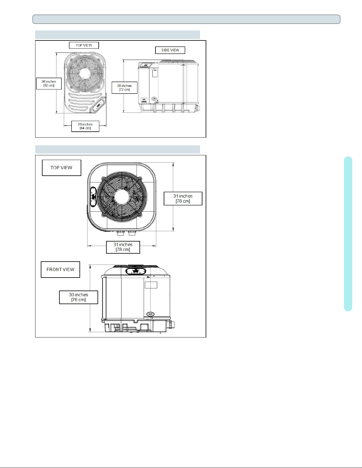
lSee "Clearances" on the next page.
Controlling Irrigation and Rainwater Runoff
lIrrigation water may damage heat pump components. Direct irrigation water away from the heat pump.
lThe heat pump will withstand normal rainfall. Do not allow a roof slope to direct rainwater onto the heat pump.
Have a gutter installed on the roof edge to direct this water away from the heat pump. Or install the heat pump in
another location.
Planning for Condensation
The heat pump can produce a large amount of condensation. The amount of water depends on air temperature
and humidity.
lInstall the heat pump with enough height to allow for water drainage.
lPlan for water drainage as needed.
Mounting Pad Requirements
lThe heat pump's base must be installed on a flat and level surface that completely supports the entire base.
lBuild the heat pump pad out of concrete or other code-approved material.
lConfirm the pad can support the weight of the heat pump. See "Weights" on page66.
lElevate the pad enough to allow for drainage.
lMake sure the pad is flat and level.
lHave the pad support the entire heat pump base in all directions.
lDo not install the heat pump on soil or grass.
lDo not allow the heat pump base to touch the building's foundation.
lDo not place the heat pump directly on a concrete floor. This can cause noise to be transmitted to an occupied
space. If necessary install vibration dampers between the heat pump base and floor.
lEquipment pad must meet all requirements of authorities having code-related jurisdiction.
Anchoring to Pad
lFollow all applicable local, state, and national requirements regarding wind load anchoring.
lThe shipping brackets used to secure the heat pump to the pallet are approved mounting (hurricane) brackets.
They should be used to anchor the heat pump to the pad.
lIf needed, contact Leisure Temp to obtain anchoring kit information. Please have the heat pump model number
and serial number when requesting support. See "Identifying Model Specifications" on page65.
1 - Installation

Page - 5
1.2 Clearances
lProper air circulation is required for the heat pump to operate efficiently. The following diagrams show the
minimum clearances required for the proper operation of the heat pump.
lAvoid storing chemical containers near the heat pump. The chemicals can cause equipment damage.
lAvoid placing objects near or on top of the heat pump. This includes shrubbery and lawn furniture. These objects
will reduce performance and efficiency and hinder maintenance access.
(Overhead Clearance)
(Top View)
LT55
(Top View)
LT400, LT600, LT700, LT800, LT1000
1 - Installation

Page - 6
1.3 Dimensions
(Leisure Temp LT55)
(Leisure Temp LT400)
1 - Installation

Page - 7
(Leisure Temp LT600)
(Leisure Temp LT700 & LT800)
1 - Installation

Page - 8
(Leisure Temp LT1000)
1.4 Plumbing
1.4.a Plumbing Requirements
NOTICE
Failure to heed the following may result in damage to equipment.
lDo not use glue on the threaded portion of the equipment’s unions. A glued-in-place union will prevent the
equipment from being properly winterized.
lThe heat pump must receive water flow within the specified minimum ranges under worst-case conditions such as
a fouled water filter.
lFailure to provide clean filtered water to the heat pump can void the product warranty.
lWater flow exceeding maximum flow rates will negatively affect the total pool filtration performance and may
damage the heat pump. This will not be covered under the equipment warranty. See "Water Flow Rates" on
page13.
lInstall a bypass valve whenever water-flow may exceed the maximum rating.
lSee "Bypass Valve Kit (# STK0135)" on page67.
lFor additional guidance testing water flow rates, please contact Leisure Temp.
lA safety-enhancing "Over Temperature Alarm"kit is strongly recommended for all spa applications.
1 - Installation

Page - 9
1.4.b Plumbing Diagrams
Plumbing diagrams are provided in this section as a planning guide to the sequence of equipment, valves, and
fittings.
lThe basic plumbing configurations for typical installations are shown.
lIf the installation does not closely follow any of the supplied plumbing diagrams, Leisure Temp Technical
Support is available for installation advice and guidance.
lConfirm water provided to the heat pump is clean and filtered.
Heat Pump with water flows equal or less than maximum listed flow rate
See "Water Flow Rates" on page13.
Heat Pump with water flows greater than maximum listed flow rate
See "Water Flow Rates" on page13.
1 - Installation

Page - 10
Heat Pump with Spillover Spa (One filter Pump)
Heat Pump with Spillover Spa (Two filter Pumps)
Heat Pump with Solar Panels in Plumbing Circuit
1 - Installation

Page - 11
Heat Pump with Gas Heater backup
Multiple Air Source Heat Pumps
1.4.c Water Connections to Heat Pump
lHeat Pump union sizes are specified on diagrams.
lConnections to site plumbing are made via PVC solvent cement to the female slip socket of the plumbing unions.
NOTICE
Failure to heed the following may result in damage to equipment.
lDo not use glue on the threaded portion of the equipment’s unions. A glued-in-place union will prevent the
equipment from being properly winterized.
1 - Installation

Page - 12
Leisure Temp LT55
(Leisure Temp LT400 and LT600)
(Leisure Temp LT700, LT800 and LT1000)
1 - Installation

Page - 13
1.4.d In-Line Chlorine Feeders
Place in-line chlorinators downstream from the heat pump and as low in elevation as possible.
lIf an erosion type feeder is used, it is recommended that a Hartford Loop be installed to protect internal heat
pump components.
lA Hartford Loop is not necessary with a Salt Chlorine Generator.
Heat Pump with Hartford Loop
1.4.e Water Flow Rates
Maintain water flow rates as indicated. Please note, these specifications relate to the heat pump only. Code-
specified whole system turnover rates must be satisfied.
NOTICE
Failure to heed the following may result in damage to equipment.
lWater flow exceeding maximum flow rates will negatively affect the total pool filtration performance and may
damage the heat pump. This will not be covered under the equipment warranty.
MODEL FLOW RATES
MINIMUM MAXIMUM
LT55 20 GPM (75.7 L/min) 45 GPM (170 L/min)
LT400 20 GPM (75.7 L/min) 45 GPM (170 L/min)
LT600 20 GPM (75.7 L/min) 45 GPM (170 L/min)
LT700 30 GPM (113.6 L/min) 70 GPM (265 L/min)
LT800 30 GPM (113.6 L/min) 70 GPM (265 L/min)
LT1000 30 GPM (113.6 L/min) 70 GPM (265 L/min)
PLEASE NOTE -
If minimum flow rates are not met, heat pump performance is reduced and performance will
suffer. Internal safety devices may deactivate the heat pump with the following errors:
lHIGH PRESSURE FAULT
lHP5 SYSTEM LOCKOUT
lLOW PRESSURE FAULT
lLP5 SYSTEM LOCKOUT
1 - Installation

Page - 14
lOperate water filtration devices per manufacturer's specifications. Dirty filters can cause a reduction of water flow
to the heat pump. An increase of 7-10 psi (48 to 69 kPa) higher than the clean filter pressure typically reduces
flow rates. This requires the filter to be cleaned or back-washed.
lKeep baskets free of debris. A large quantity of debris in the pump and skimmer baskets can reduce water flow.
lCheck for improper valve settings. A partially closed valve after the filter, or a full-open bypass around the heat
pump, will cause insufficient water flow through the heat pump.
lThe maximum static pressure (or operating pressure) is 50 psi (345 kPa). These specifications relate to the heat
pump only.
lCode-specified whole system turnover rates must be satisfied.
1.4.f Adjusting Water Flow Using ΔT (Delta-T)
The Delta-T is the temperature difference between the water temperatures entering and leaving the heat pump.
The equipment can be fine-tuned for maximum performance by balancing water flow rates to maintain an
ideal ∆T.
The adjustment procedure must be completed with the unit in heating mode.
lInstalled temperature ports are required to perform the following procedures.
lThese ports are typically located on the pool in and pool out water lines approximately six inches away from the
heat pump.
PLEASE NOTE -
lThe installation of temperature ports is required for all commercial applications.
lThe installation of temperature ports is strongly recommended for residential installations.
Temperature Port
(Shown with Probe)
1. Adjust the thermostat to its lowest setting with the unit in
heating mode.
2. Deactivate the water filtration pump.
3. Confirm that the filters leading to the heat pump are clean.
4. Adjust the valves controlling water headed towards the heat
pump to the half-open position.
5. Adjust the valves controlling water leading away from the
heat pump to a fully open position.
6. Activate the pool water filtration pump.
7. Slowly raise the thermostat temperature until the heat pump
activates.
lAfter a three-minute delay, the heat pump's compressor will start.
8. With the heat pump running, confirm the filtration pump is operating properly with adequate flow and no short
cycling.
9. Wait for water temperatures to stabilize (approximately 5 minutes).
12. Adjust valves in the following order using the temperature chart provided.
a. Adjust the valve that controls water exiting the heat pump until the correct temperature differential is
achieved. Match the temperature measured with a temperature probe to the chart.
b. Wait for water temperatures to stabilize. Then check the temperature again. Re-adjust the valve as needed.
13. Mark valves at these positions for future reference.
1 - Installation

Page - 15
MODEL TEMPERATURE
LT55 2° to 5° F
(1.1° C to 2.8° C)
LT400 2° to 5° F
(1.1° C to 2.8° C)
LT600 3° to 6° F
(1.7° C to 3.3° C)
LT700 3° to 7° F
(1.7° C to 3.9° C)
LT800 3° to 7° F
(1.7° C to 3.9° C)
LT1000 3° to 7° F
(1.7° C to 3.9° C)
Table 1 - Temperature Chart
PLEASE NOTE -
lTemperature differences are based on pool water temperatures of 69° to 75° F. (20.5° to
23.8° C)
lFor water temperatures outside this range, contact Leisure Temp. See "Contacts" on page1.
1.4.g Maintaining Ability to Winterize
Do not glue the threaded portion of the unions. The unions are used to decouple the heat pump from the
plumbing system during hard freeze conditions.
NOTICE
Failure to heed the following may result in damage to equipment.
lDo not use glue on the threaded portion of the equipment’s unions. A glued-in-place union will prevent the heat
pump from being properly winterized.
1.4.h Adjusting Water Pressure Switch (Select Units)
Adjust the water pressure switch when heat pump attempts to operate without water flow.
Before attempting any adjustments confirm the following :
lThe filter is clean.
lFilter pump is operating.
lThe valves are set to direct the appropriate amount of water through the
heat pump. See "Water Flow Rates" on page13.
l"NO POOL/SPA WATER FLOW" is displayed (or displays
intermittently).
DANGER Failure to heed the following will result in injury or death.
lDeactivate power while routing wiring to control board.
lFollow all National Electric Codes (NEC) and/or State and Local guidelines.
1 - Installation

Page - 16
WARNING Failure to heed the following may result in injury or death.
lWater Pressure Switch adjustment procedure to be performed by experienced service personnel only; procedure
must not be attempted by individuals lacking adequate electrical and mechanical experience.
NOTICE
Failure to heed the following may result in damage to equipment.
lIf the heat pump continues to operate after a water pressure switch adjustment, deactivate equipment and perform
additional troubleshooting.
1. Remove heat pump access panel.
2. Locate the water pressure switch. It will be outside and along
the bottom edge of the electrical enclosure. The exact location
varies by model.
3. Activate the filter pump.
4. Apply power to heat pump.
5. Slowly rotate the adjustment wheel on the switch. Keep
turning the wheel until the heat pump indicates it is receiving
water. The display will no longer indicate "NO POOL/SPA
WATER FLOW".
6. Deactivate filter pump. If correctly adjusted, theheat pump
will deactivate and the display will show "NO POOL/SPA
WATER FLOW".
7. Re-install heat pump access panel.
8. If the heat pump continues to operate without water flow, the installation of a grid flow switch may be required.
lThis can become necessary if the heat pump is installed below the elevation of the body of water to be heated.
The standing pressure from the water can cause the water pressure switch to activate when the circulation
pump is off. Therefore a water flow switch must be used in place of a water pressure switch to determine if
incoming water is being sent to the heat pump. See "Grid Flow Switch (# 0040S)" on page67.
9. If the heat pump continues to operate without water flow, contact Leisure Temp.
1 - Installation

Page - 17
1.5 Electrical
1.5.a Electrical Requirements
DANGER Failure to heed the following will result in injury or death.
lDeactivate power while routing wiring to control board.
lFollow all National Electric Codes (NEC) and/or State and Local guidelines.
WARNING Failure to heed the following may result in injury or death.
lThe information contained in this section is intended for use by qualified electricians familiar with electrical
service-industry safety standards and methods.
lLocate the equipment disconnect as near to the heat pump as possible. Always satisfy applicable codes and
standards.
lNever mount power-disconnects directly to the heat pump.
lIn sizing power wiring, be especially aware of up-sizing requirements necessary due to wiring distances. Always
satisfy applicable codes and standards.
lLeisure Temp heat pumps are designed to use copper conductors, only. Do not use aluminum wire.
lIf multiple heat pumps are on-site, confirm that the multiple heat pump configuration has been utilized. See
"Connecting Multiple Heat Pumps (Primary / Secondary)" on page35. This will prevent multiple heat pumps
attempting to start at the same time, causing an excessive power drop at start-up.
Electrical Standards
Standards Title
NFPA 70, Nat'l Elec.
Code 2017
The electrical installation must conform to the current
version of the National Electric Code (NEC), and all
applicable local and state codes
IEC 60335-1 Household and similar electrical appliances - Safety -
General Requirements
IEC 60335-2 Household and similar electrical appliances - Safety –
Particular requirements for electrical heat pumps, air-
conditioners, and dehumidifiers
UL 1995 & CSA C22.2
No. 236-15 Standard for Safety - Heating and cooling equipment
Table 2 - Standards
Grounding and Bonding
Follow local code requirements for proper grounding and bonding of heat pump equipment.
lA bonding lug has been provided on the heat pump.
1 - Installation
This manual suits for next models
5
Table of contents
Other Leisure Temp Swimming Pool Heater manuals
Popular Swimming Pool Heater manuals by other brands

Mountfield
Mountfield SPIRAL Instructions for installation and operation

Jandy
Jandy LRZ Electronic Installation and operation manual

Lochinvar
Lochinvar Power-fin 502 Service manual

Astral Pool
Astral Pool Viron Series Installation and operating instructions

SunStar
SunStar STR-8 installation manual

Envision
Envision AC-1750B installation manual