Page 3 of 25POP-UP PUSH 8 ECO Operator’s Safety and Maintenance Handbook ( rev.0.0.1.0210)
Section 1
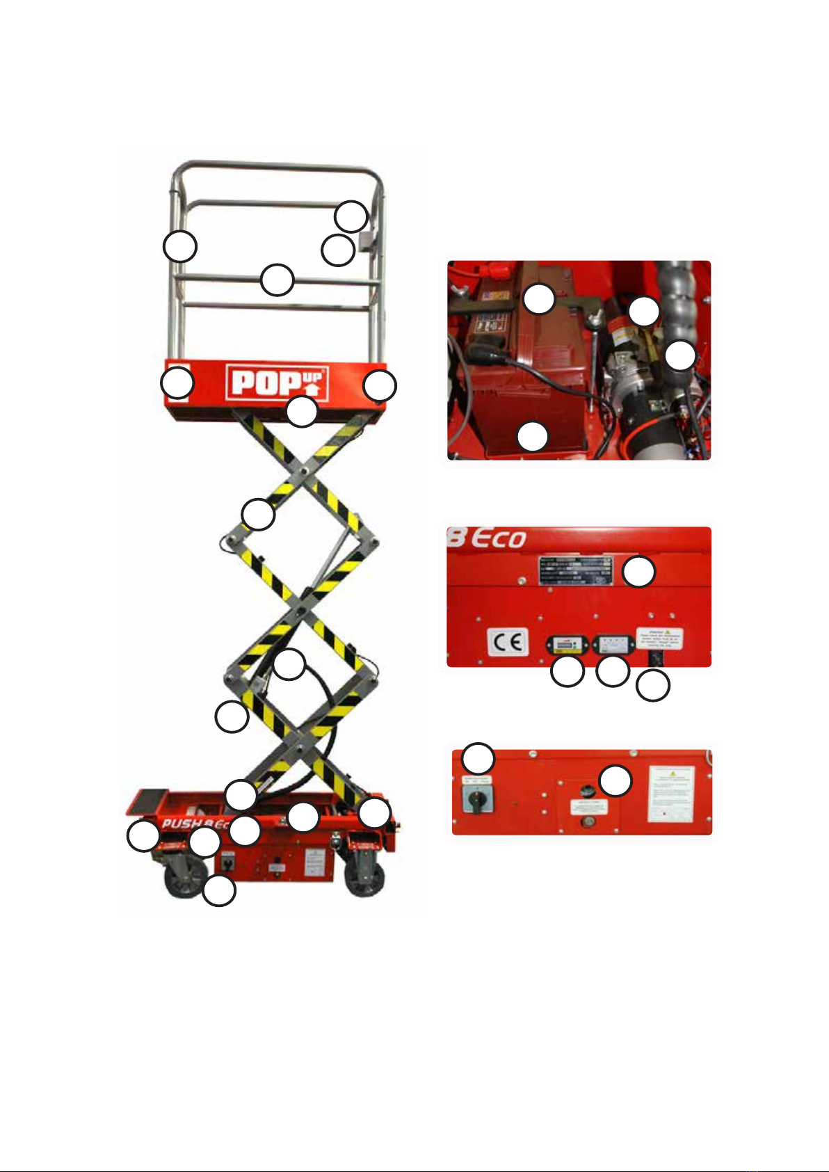
DESCRIPTION
Introduction
This handbook provides information on the safe operation of this work
platform. Operators should read and understand all of the information
contained within this manual prior to operating the work platform.
The handbook contains several warnings, these indicate situations which if not
avoided could result in serious injury or death to persons, or damage to the
machine or property.
Additional copies of this handbook are available from the manufacturer at the
address below. Information contained in this handbook is based on the latest
product information at time of publication.
Pop-Up Products Ltd operate a policy of continuous improvement and therefore
reserve the right to make product changes at any time without obligation.
Description
The POP-UP PUSH 8 ECO is a scissor lift type work platform, which is
manoeuvred manually into work positions and elevated and lowered using an
electro-hydraulic control system.
The standard machine includes the following standard features:
• 240kg safe working load
• 4.5 metre working height
• 1.72 metre stowed height
• Easily manoeuvrable
• Pass through standard doors
• Simple operation
• Steel guard rails
• Non-slip platform
• Steerable wheels
• Manual brakes on rear swivel wheels
• Auto brakes on front xed wheels
• Anti-crushing lowering delay
• Integral battery charger
• Emergency lowering facility
• Easily transportable
• Low maintenance
• Complies with EN280:2001
• Stabilisers (optional if auto brakes tted)
Intended use
The machine has been designed to comply with the safety requirements of the
Machinery Directive 2006/42/EC taking guidance from the European Standard BS
EN280:2001 + A2:2009 Mobile Elevating Work Platforms.
The machine is intended to be used to lift persons, plus essential tools and
materials, to enable work to be undertaken at height. Typical applications will
include maintenance, cleaning, painting, etc. at varying heights above ground level.
WARNING
THE MACHINE MUST NOT BE USED IN APPLICATIONS OR FOR USES
OUTSIDE OF THE SCOPE OF THIS HANDBOOK. SHOULD A CERTAIN
APPLICATION NOT BE COVERED, THEN THE MANUFACTURER SHOULD
BE CONTACTED