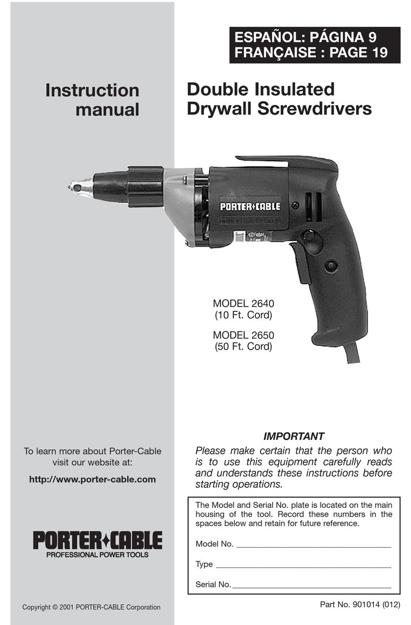
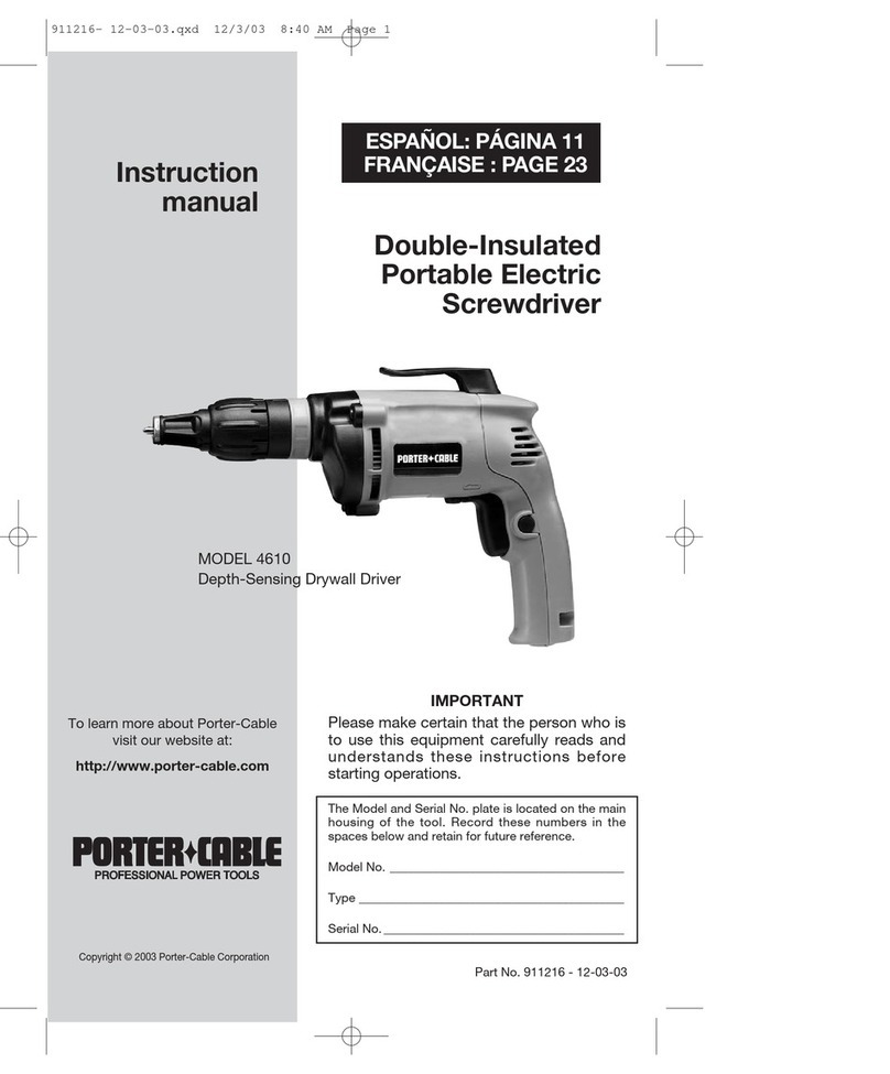
Porter-Cable 4630 User manual

Double Insulated
Portable Electric
Screwdrivers
Part No. 896132 - 06-03-03
ESPAÑOL: PÁGINA 13
FRANÇAISE : PAGE 27
MODELS 4630 and 4634
Depth Sensing Drywall and Deck Drivers
MODEL 4640
Depth Sensing Fastener Driver
Instruction
manual
The Model and Serial No. plate is located on the main
housing of the tool. Record these numbers in the
spaces below and retain for future reference.
Model No. ______________________________________
Type ___________________________________________
Serial No. _______________________________________
IMPORTANT
Please make certain that the person who is
to use this equipment carefully reads and
understands these instructions before
starting operations.
To learn more about Porter-Cable
visit our website at:
http://www.porter-cable.com
Copyright © 2003 Porter-Cable Corporation

WORK AREA
1. Keep your work area clean and well lit. Cluttered benches and dark
areas invite accidents.
2. Do not operate power tools in explosive atmospheres, such as in
the presence of flammable liquids, gases, or dust. Power tools create
sparks which may ignite the dust or fumes.
3. Keep bystanders, children, and visitors away while operating a
power tool. Distractions can cause you to lose control.
ELECTRICAL SAFETY
1. Double insulated tools are equipped with a polarized plug (one
blade is wider than the other). This plug will fit in a polarized outlet only
one way. If the plug does not fit fully in the outlet, reverse the plug. If it
still does not fit, contact a qualified electrician to install a polarized
outlet. Do not change the plug in any way. Double Insulation eliminates
the need for the three wire grounded power cord and grounded power supply
system.
2
SAFETY GUIDELINES - DEFINITIONS
indicates an imminently hazardous situation which, if not
avoided, will result in death or serious injury.
indicates a potentially hazardous situation which, if not
avoided,could result in death or serious injury.
indicates a potentially hazardous situation which, if not
avoided,may result in minor or moderate injury.
used without the safety alert symbol indicates potentially
hazardous situation which, if not avoided, may result in
property damage.
This manual contains information that is important for you to know and under-
stand. This information relates to protecting YOUR SAFETY and PREVENTING
EQUIPMENT PROBLEMS. To help you recognize this information, we use the
symbols below. Please read the manual and pay attention to these sections.
Read and understand all instructions. Failure to
follow all instructions listed below, may result in electric shock, fire
and/or serious personal injury.
SAVE THESE INSTRUCTIONS.
GENERAL SAFETY RULES
Some dust created by power sanding, sawing, grinding, drilling,
and other construction activities contains chemicals known (to the
State of California) to cause cancer, birth defects or other reproductive harm. Some
example of these chemicals are:
●lead from lead-based paints
●crystalline silica from bricks and cement and other masonry products
●arsenic and chromium from chemically-treated lumber
Your risk from these exposures varies, depending on how often you do this type
of work. To reduce your exposure to these chemicals: work in a well ventilated
area, and work with approved safety equipment, always wear MSHA/NIOSH
approved, properly fitting face mask or respirator when using such tools.

3
2. Avoid body contact with grounded surfaces such as pipes, radiators,
ranges and refrigerators. There is an increased risk of electric shock if your
body is grounded.
3. Don’t expose power tools to rain or wet conditions. Water entering a
power tool will increase the risk of electric shock.
4. Do not abuse the cord. Never use the cord to carry the tools or pull
the plug from an outlet. Keep cord away from heat, oil, sharp edges or
moving parts. Replace damaged cords immediately. Damaged cords
increase the risk of electric shock.
5. When operating a power tool outside, use an outdoor extension cord
marked “W-A” or “W”. These cords are rated for outdoor use and reduce the
risk of electric shock.
PERSONAL SAFETY
1. Stay alert, watch what you are doing, and use common sense when
operating a power tool. Do not use tool while tired or under the influence
of drugs, alcohol, or medication. A moment of inattention while operating
power tools may result in serious personal injury.
2. Dress properly. Do not wear loose clothing or jewelry. Contain long
hair. Keep your hair, clothing, and gloves away from moving parts. Loose
clothes, jewelry, or long hair can be caught in moving parts.
3. Avoid accidental starting. Be sure switch is OFF before plugging in.
Carrying tools with your finger on the switch or plugging in tools that have the
switch ON invites accidents.
4. Remove adjusting keys or wrenches before turning the tool ON. A
wrench or a key that is left attached to a rotating part of the tool may result in
personal injury.
5. Do not overreach. Keep proper footing and balance at all times.
Proper footing and balance enable better control of the tool in unexpected
situations.
6. Use safety equipment. Always wear eye protection. Dust mask, non-
skid safety shoes, hard hat, or hearing protection must be used for
appropriate conditions.
TOOLS USE AND CARE
1. Use clamps or other practical way to secure and support the
workpiece to a stable platform. Holding the work by hand or against your
body is unstable and may lead to loss of control.
2. Do not force tool. Use the correct tool for your application. The
correct tool will do the job better and safer at the rate for which it is designed.
3. Do not use tool if switch does not turn it ON or OFF. A tool that cannot
be controlled with the switch is dangerous and must be repaired.
4. Disconnect the plug from the power source before making any
adjustments, changing accessories, or storing the tool. Such preventive
safety measures reduce the risk of starting the tool accidentally.
5. Store idle tools out of reach of children and other untrained persons.
Tools are dangerous in the hands of untrained users.
6. Maintain tools with care. Keep cutting tools sharp and clean. Properly
maintained tools, with sharp cutting edges are less likely to bind and are
easier to control.

4
7. Check for misalignment or binding of moving parts, breakage of
parts, and any other condition that may affect the tool’s operation. If
damaged, have the tool serviced before using. Many accidents are caused
by poorly maintained tools.
8. Use only accessories that are recommended by the manufacturer for
your model. Accessories that may be suitable for one tool may become
hazardous when used on another tool.
SERVICE
1. Tool service must be performed only by qualified repair personnel.
Service or maintenance performed by unqualified personnel may result in a
risk of injury.
2. When servicing a tool, use only identical replacement parts. Follow
instructions in the Maintenance Section of this manual. Use of
unauthorized parts or failure to follow Maintenance Instructions may create a
risk of electric shock or injury.
1. HOLD TOOL BY INSULATED GRIPPING SURFACES WHEN
PERFORMING AN OPERATION WHERE THE CUTTING TOOL MAY
CONTACT HIDDEN WIRING OR ITS OWN CORD. Contact with a “live”
wire will also make exposed metal parts of the tool “live” and will shock
the operator.
2. VERIFY the direction of rotation before starting the tool.
3. NEVER ATTEMPT TO CHANGE DIRECTION of rotation while switch is
“ON”. To do so, may damage interlock feature built into switch. Be sure
switch is “OFF” and motor has completely stopped before changing
direction of rotation.
4. SOME WOOD CONTAINS PRESERVATIVES WHICH CAN BE TOXIC.
Take extra care to prevent inhalation and skin contact when working with
these materials. Request, and follow, any safety information available from
your material supplier.
ADDITIONAL SPECIFIC SAFETY RULES
Technical Service Manager
Porter-Cable Corporation
4825 Highway 45 North
Jackson, TN 38305
There are certain applications for which this tool was
designed. Porter-Cable strongly recommends that this tool
NOT be modified and/or used for any application other than for
which it was designed. If you have any questions relative to its
application DO NOT use the tool until you have written Porter-
Cable and we have advised you.

5
SYMBOL DEFINITION
V ........................ volts
A ........................ amperes
Hz ........................ hertz
W ........................ watts
kW ........................ kilowatts
µF ........................ microfarads
l ........................ liters
kg ........................ kilograms
N/cm2........................ newtons per square centimeter
Pa ........................ pascals
h ........................ hours
min ........................ minutes
s ........................ seconds
........................ alternating current
3 ........................ three-phase alternating current
3N........................ three-phase alternating current with neutral
........................ direct current
n0........................ no load
........................ alternating or direct current
........................ Class II Construction
........................ splash-proof construction
........................ watertight construction
…/min ........................ revolutions or reciprocation per minute
REPLACEMENT PARTS
When servicing, use only identical replacement parts.
MOTOR
Many Porter-Cable tools will operate on either D.C., or single phase 25 to 60
cycle A.C. current and voltage within plus or minus 5 percent of that shown
on the specification plate on the tool. Several models, however, are designed
for A.C. current only. Refer to the specification plate on your tool for proper
voltage and current rating.
Do not operate your tool on a current on which the voltage
is not within correct limits. Do not operate tools rated A.C.
only on D.C. current. To do so may seriously damage the
tool.

FOREWORD
Porter-Cable screwdrivers are designed to install or remove various sizes and
types of fasteners.
TO START AND STOP TOOL
Make sure that the switch is off before connecting the
tool to the power source.
1. Make sure that the switch is
“OFF”. Make sure that the power
circuit voltage is the same as that
shown on the specification plate
of the tool. Connect the drill to
the power circuit.
2. Squeeze the TRIGGER SWITCH
(A) Fig. 1 to start the motor.
Release the trigger to stop the
motor.
6
Fig. 1
A
B
C
Length of Cord in Feet
115V 25 Ft. 50 Ft. 100 Ft. 150 Ft. 200 Ft. 250 Ft. 300 Ft. 400 Ft. 500 Ft.
230V 50 Ft. 100 Ft. 200 Ft. 300 Ft. 400 Ft. 500 Ft. 600 Ft. 800 Ft. 1000 Ft.
0-2 18 18 18 16 16 14 14 12 12
2-3 18 18 16 14 14 12 12 10 10
3-4 18 18 16 14 12 12 10 10 8
4-5 18 18 14 12 12 10 10 8 8
5-6 18 16 14 12 10 10 8 8 6
6-8 18 16 12 10 10 8 6 6 6
8-10 18 14 12 10 8 8 6 6 4
10-12 16 14 10 8 8 6 6 4 4
12-14 16 12 10 8 6 6 6 4 2
14-16 16 12 10 8 6 6 4 4 2
16-18 14 12 8 8 6 4 4 2 2
18-20 14 12 8 6 6 4 4 2 2
Nameplate Ampere Rating
RECOMMENDED EXTENSION CORD SIZES FOR USE WITH PORTABLE ELECTRIC TOOLS
OPERATING INSTRUCTIONS
EXTENSION CORD SELECTION
If an extension cord is used, make sure the conductor size is large enough to
prevent excessive voltage drop which will cause loss of power and possible
motor damage. A table of recommended extension cord sizes will be found
in this section. This table is based on limiting line voltage drop to 5 volts (10
volts for 230 volts) at 150% of rated amperes.
If an extension cord is to be used outdoors it must be marked with the
suffix W-A or W following the cord type designation. For example – SJTW-A
to indicate it is acceptable for outdoor use.

7
3. A lock button (B) Fig. 1 is provided to keep the motor running without
holding the trigger switch “ON”.
TO LOCK the trigger switch “ON”, squeeze the trigger as far as it will go,
push in lock button and release trigger.
TO UNLOCK the lock button, squeeze the trigger and release, leaving
the lock button free to spring out.
NOTE: The lock button can be engaged only when the tool is running at
maximum speed.
Never use the lock button when the tool may have to be
stopped suddenly.
4. These tools will operate in either the forward direction (clockwise rotation)
for drilling holes, or the reverse direction (counter-clockwise rotation) for
releasing jammed drill bits. For counter-clockwise rotation, stop the
motor by releasing the trigger switch and push the reversing switch (C)
Fig. 1 toward the right side of the drill, or in the opposite direction for
clockwise rotation.
Never attempt to change direction of rotation while the
switch is “ON”. To do so, may damage interlock feature built
into switch. Be sure that the switch is “OFF” and the motor
has completely stopped before changing the direction of
rotation.
5. VARIABLE SPEED – As the trigger switch is squeezed, the tool speed
increases.
TO CHANGE HEX NUTSETTER – MODEL 4640
1. Pull the Depth Stop Assembly (A) Fig. 2 from the clutch housing (B).
2. Pull the nutsetter (C) Fig. 3 straight out. If it is difficult to remove, grip it
with pliers and pull.
3. Push the nutsetter into the screwdriver spindle until the ball in the spindle
snaps into the groove in the nutsetter shank.
4. Replace the depth stop assembly and adjust for depth of drive (see
“ADJUST DEPTH STOP, MODEL 4640”).
Fig. 2 Fig. 3
ABC
DISCONNECT TOOL FROM POWER SOURCE.

8
ADJUST DEPTH STOP – MODEL 4640
1. Turn the adjusting collar (A) Fig. 2 until the end of the depth stop is flush
with the end of the nutsetter. Do not push the nutsetter in. This will engage
the internal drive.
2. Drive a test fastener into a piece of scrap material identical to the
workpiece. Examine the results of the drive and make any necessary
depth stop adjustments.
a) To increase the depth of drive, repeat STEP 1 and turn the adjusting
collar so that the end of the nutsetter extends beyond the end of the
depth stop.
b) To decrease the depth of drive, repeat STEP 1 and turn the adjusting
collar so that the end of the depth stop extends beyond the end of
the nutsetter.
Each click of the adjusting collar results in .007" change in the depth of drive.
3. Repeat STEPS 1 and 2 until the desired result is obtained.
CHANGE BIT HOLDER – MODELS 4630, 4634
1. Pull the Depth Stop Assembly (A) Fig. 4 from the clutch housing.
2. Pull the bit holder (C) Fig. 4 out.
If it is difficult to remove, grip it
with pliers and pull. NOTE: Bit
(D) Fig. 4 may be removed from
the bit holder by pulling it
straight out.
3. Push new bit holder into the
spindle, snapping it into place.
4. Replace Depth Stop Assembly
and adjust the depth stop (see
“ADJUST DEPTH STOP,
MODELS 4630 AND 4634”)
ADJUST DEPTH STOP – MODELS 4630 AND 4634
1. Turn the adjusting collar until the end of the bit extends 3/32" beyond the
end of the depth stop. Do not push the bit holder in. This will engage the
internal drive.
2. Drive a test fastener in a piece of scrap material identical to that to be
used. Examine results of drive and make additional depth stop
adjustments:
a) To increase the depth of drive, repeat STEP 1 and turn the adjusting
collar so that the end of the bit extends further than the end of the
depth stop.
b) To decrease depth of drive, repeat STEP 1 and turn the adjusting
collar so that the end of the bit is closer to the end of depth stop.
Each click of the adjusting collar results in .007" change in the depth
of drive.
3. Repeat STEPS 1 and 2 until the desired result is obtained.
Fig. 4
A
C
D
DISCONNECT TOOL FROM POWER SOURCE.

9
DRIVING DRYWALL SCREWS – MODELS 4630, 4634
NOTE: Maximum size screw for use with this tool is #12 Wood Screw.
1. Install a drywall bit and bit holder in the screwdriver.
2. Set the screwdriver for the correct rotation.
3. Start the screwdriver and place a drywall screw on the bit.
Do not exert pressure on the screw while performing this
operation.
4. Place the end of the screw in the desired location and remove your
fingers.
5. Apply forward pressure to the drive screw until the depth stop rests on the
surface of the work. Adjust the depth stop so that the fastener head is
sunk just below the surface of the wallboard.
DRIVING SELF-DRILLING/TAPPING SCREWS – MODELS 4640
NOTE: Maximum size screws for use with this tool are #12 wood screws and
1/4" self-drilling/tapping screws.
These screws drill and tap their own hole as they are driven. This differs from
self-tapping screws in that pre-drilled holes for tapping are not required. To
drive these screws:
1. Install the proper nutsetter that fits the screw to the screwdriver.
2. Set the screwdriver for the correct rotation.
3. Start the screwdriver and insert the head of the screw in the nutsetter.
Do not exert pressure on the screw while performing this
operation.
4. Place the end of the screw in the desired location and remove your
fingers.
5. Apply forward pressure to drive screw until depth stop rests on the
surface of the work. Adjust the depth stop so that the fastener head seats
firmly on the work. Avoid seating the fastener too deep to prevent
shearing off the head.
TO REMOVE SCREWS – ALL MODELS
1. Remove the Depth Stop Assembly.
2. Install a proper bit that fits the screw.
3. Set the screwdriver for reverse rotation.
4. Place the bit on the screw and apply forward pressure.
5. Start the screwdriver.

10
CHECK CLUTCH CONDITION
Periodically, depending on use,
screwdriver clutch jaws should be
inspected for wear. This may be
done by removing the screwdriver
mechanism housing (A) Fig. 5 from
the power unit.
NOTE: The clutch housing is attached to the power unit with left-hand
threads. The depth stop assembly may be removed from the clutch housing
by pulling it straight off. Remove the clutch housing by turning the clutch
housing clockwise.
NOTE: Be careful not to lose the small spring that is in the end of the power
unit spindle shaft.
Note the condition of the 3-jaw clutch faces on the power unit and screwdriver
mechanism. If they are badly rounded where the angular face meets the top
surface, or appear otherwise worn or faulty, or if the clutch elements are not
securely held in place on their respective shafts by the snap rings, return the
entire tool to your AUTHORIZED PORTER-CABLE SERVICE STATION for
service.
Proceed if the jaws are not seriously worn and there are no other apparent
faults in the mechanism. Be sure that the mechanism and all internal areas are
clean and free of chips or other foreign material and brush a thin coat of
PORTER-CABLE gear lubricant on the clutch elements and surrounding
areas. Attach the screwdriver mechanism to the power unit. Be sure the spring
is in the spindle shaft. NOTE: The housing threads are left-hand thread.
Fig. 5
A
MAINTENANCE
DISCONNECT TOOL FROM POWER SOURCE.

11
KEEP TOOL CLEAN
Periodically blow out all air passages with dry, compressed air. All plastic
parts should be cleaned with soft damp cloth. NEVER use solvents, to clean
plastic parts. They could possibly dissolve or otherwise damage the material.
Wear safety glasses while performing this operation.
FAILURE TO START
If your tool fails to start, check the prongs on the cord plug to see if they are
making good contact with the outlet. Check for blown fuses or open circuit
breakers in the line.
BRUSH INSPECTION AND LUBRICATION
For your continued safety and electrical protection, brush inspection and
replacement on this tool should ONLY be performed by an AUTHORIZED
PORTER-CABLE SERVICE STATION or a PORTER-CABLE/DELTA FACTORY
SERVICE CENTER.
At approximately 100 hours of use, take or send your tool to your nearest
authorized Porter-Cable Service Station to be thoroughly cleaned and
inspected. Have worn parts replaced and lubricate with fresh lubricant. Have
new brushes installed, and test the tool for performance.
Any loss of power before the above maintenance check may indicate the
need for immediate servicing of your tool. DO NOT CONTINUE TO OPERATE
TOOL UNDER THIS CONDITION. If proper operating voltage is present, return
your tool to the service station for immediate service.
SERVICE AND REPAIRS
All quality tools will eventually require servicing or replacement of parts due to
wear from normal use. These operations, including brush inspection and
replacement, should ONLY be performed by either an AUTHORIZED
PORTER-CABLE SERVICE STATION or a PORTER-CABLE/DELTA FACTORY
SERVICE CENTER. All repairs made by these agencies are fully guaranteed
against defective material and workmanship. We cannot guarantee repairs
made or attempted by anyone other than these agencies.
Should you have any questions about your tool, feel free to write us at any
time. In any communications, please give all information shown on the
nameplate of your tool (model number, type, serial number, etc.).

12
PORTER-CABLE LIMITED
ONE YEAR WARRANTY
Porter-Cable warrants its Professional Power Tools for a period of one year from the date of original
purchase. We will repair or replace at our option, any part or parts of the product and accessories
covered under this warranty which, after examination, proves to be defective in workmanship or
material during the warranty period. For repair or replacement return the complete tool or accessory,
transportation prepaid, to your nearest Porter-Cable Service Center or Authorized Service Station.
Proof of purchase may be required. This warranty does not apply to repair or replacement required
due to misuse, abuse, normal wear and tear or repairs attempted or made by other than our Service
Centers or Authorized Service Stations.
ANY IMPLIED WARRANTY, INCLUDING THE IMPLIED WARRANTIES OF MERCHANTABILITY AND
FITNESS FOR A PARTICULAR PURPOSE, WILL LAST ONLY FOR ONE (1) YEAR FROM THE DATE
OF PURCHASE.
To obtain information on warranty performance please write to: PORTER-CABLE CORPORATION,
4825 Highway 45 North, Jackson, Tennessee 38305; Attention: Product Service. THE FOREGOING
OBLIGATION IS PORTER-CABLE’S SOLE LIABILITY UNDER THIS OR ANY IMPLIED WARRANTY
AND UNDER NO CIRCUMSTANCES SHALL PORTER-CABLE BE LIABLE FOR ANY INCIDENTAL OR
CONSEQUENTIAL DAMAGES. Some states do not allow limitations on how long an implied warranty
lasts or the exclusion or limitation of incidental or consequential damages, so the above limitation or
exclusion may not apply to you.
This warranty gives you specific legal rights and you may also have other legal rights which vary from
state to state.
A complete line of accessories is available from your Porter-Cable · Delta Supplier, Porter-
Cable · Delta Factory Service Centers, and Porter-Cable Authorized Service Stations.
Please visit our Web Site www.porter-cable.com for a catalog or for the name of your
nearest supplier.
Since accessories other than those offered by Porter-Cable · Delta,
have not been tested with this product use of such accessories could
be hazardous. For safest operation, only Porter-Cable ·Delta
recommended accessories should be used with this product.
ACCESSORIES

Desatornilladores
(Desarmadores) Portátiles
Eléctricos con
Aislamiento Doble
Manual de
Instrucciones
La placa de Modelo y Número de Serie está localizada
en la caja principal de la herramienta. Anote estos
números en las líneas de abajo y guárdelos para
referencia en el futuro.
Número de modelo ______________________________
Tipo____________________________________________
Número de serie_________________________________
Número de parte 896132 - 06-03-03
IMPORTANTE
Asegúrese de que la persona que va a usar
esta herramienta lea cuidadosamente y
comprenda estas instrucciones antes de
empezar a operarla.
Desatornilladores para Paredes
en Seco con Tope de
Profundidad
MODELOS 4630 y 4634
Desatornilladores para
Sujetadores con Tope
de Profundidad
MODELO 4640
Para obtener más información
sobre Porter-Cable,
visite nuestro sitio web en:
http://www.porter-cable.com
ENGLISH: PAGE 1
FRANÇAISE : PAGE 27

14
Indica una situación de inminente riesgo, la cual, si no es
evitada, causará la muerte o lesiones serias.
Indica una situación potencialmente riesgosa, que si no es
evitada, podría resultar en la muerte o lesiones serias.
Indica una situación potencialmente peligrosa, la cual, si no
es evitada, podría resultar en lesiones menores o mode-
radas.
Usado sin el símbolo de seguridad de alerta indica una
situa-ción potencialmente riesgosa la que, si no es evitada,
podría causar daños en la propiedad.
PAUTAS DE SEGURIDAD/DEFINICIONES
Algunos tipos de aserrín creados por máquinas eléctricas de
lijado, aserrado, amolado, perforado u otras actividades de la
construcción, contienen materiales químicos conocidos (en el Estado de California)
como causantes de cáncer, defectos de nacimiento u otros daños del aparato
reproductivo. Algunos ejemplos de dichos productos químicos son:
●El plomo contenido en algunas pinturas con base de plomo
●Sílice cristalizado proveniente de los ladrillos, el cemento y otros
productos de albañilería
●Arsénico y cromo provenientes del tratamiento químico dado a la madera
con equipo de seguridad aprobado,
use siempre protección facial o respirador
MSHA / NIOSH aprobados cuando deba utilizar dichas herramientas.
Lea y comprenda todas las siguientes
instrucciones. El no seguir las siguientes instrucciones puede resultar
en un choque eléctrico, en un incendio y/o en una herida personal.
GUARDE ESTAS INSTRUCCIONES
Other manuals for 4630
1
This manual suits for next models
2
Table of contents
Other Porter-Cable Power Screwdriver manuals

Porter-Cable
Porter-Cable 2640 User manual

Porter-Cable
Porter-Cable 4610 User manual

Porter-Cable
Porter-Cable 4630 User manual

Porter-Cable
Porter-Cable PCC520 User manual

Porter-Cable
Porter-Cable 987 User manual

Porter-Cable
Porter-Cable PCC842L User manual

Porter-Cable
Porter-Cable 6640 User manual

Porter-Cable
Porter-Cable Adjustable clutch 7531 User manual