Portland Tool & Die MDT-4000 User manual

For your safety, read and understand manual before use.
Ver: 1.0
8-Aug-2022
MDT-4000
Angular Positioning Stage
User Manual
Original Instructions

MDT-4000 User Manual (Original Instructions)
Ver: 1.0
Page 2 of 37
8-Aug-2022
1. PRODUCT OVERVIEW ..................................................................................................................................... 4
2. SAFETY CONSIDERATIONS .............................................................................................................................. 5
2.1. SAFETY STANDARD COMPLIANCE STATEMENT..................................................................................................... 5
2.2. SAFETY SYMBOLS ........................................................................................................................................ 5
2.3. EXPLOSION HAZARD .................................................................................................................................... 5
2.4. DESCRIPTION OF INTENDED USE...................................................................................................................... 5
2.5. LIST OF PROHIBITED USES.............................................................................................................................. 6
2.6. WARNINGS ............................................................................................................................................... 6
2.7. PERSONAL PROTECTIVE EQUIPMENT................................................................................................................ 6
3. REGULATORY MARKINGS ............................................................................................................................... 7
4. SYSTEM SPECIFICATIONS ................................................................................................................................ 8
4.1. MECHANICAL SPECS .................................................................................................................................... 8
4.2. MOTION................................................................................................................................................... 8
4.3. ELECTRICAL SPECS....................................................................................................................................... 8
4.4. ENVIRONMENTAL SPECS ............................................................................................................................... 9
4.5. EMC EMISSION.......................................................................................................................................... 9
4.6. EMC IMMUNITY......................................................................................................................................... 9
4.7. ELECTROSTATIC DISCHARGE (ESD).................................................................................................................. 9
4.8. EXPECTED SERVICE LIFE ................................................................................................................................ 9
5. INSTALLATION .............................................................................................................................................. 10
5.1. UNPACKING AND INITIAL SETUP INSTRUCTIONS................................................................................................. 10
5.2. AC MAINS DISCONNECT.............................................................................................................................. 12
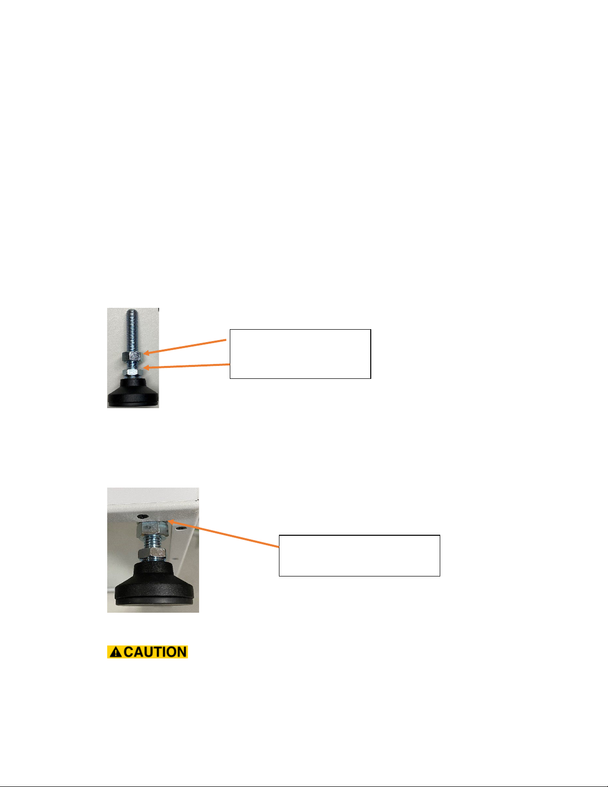
5.3. INSTALLATION CONFIGURATION:FREESTANDING USING LEVELING LEGS .................................................................. 12
5.4. INSTALLATION CONFIGURATION:BOLTED TO FLOOR .......................................................................................... 12
5.5. INSTALLATION CONFIGURATION:INVERTED ON CEILING...................................................................................... 12
5.6. ADDITIONAL INSTALLATION WARNINGS.......................................................................................................... 13
5.7. CABLE ROUTING GUIDELINES........................................................................................................................ 16
5.8. SAFETY GUIDELINES FOR FIXTURING ATTACHED TO THE TURNTABLE ....................................................................... 16
6. SYSTEM OPERATION..................................................................................................................................... 17
6.1. FRONT PANEL ELEMENTS............................................................................................................................ 17
6.2. REAR PANEL ELEMENTS.............................................................................................................................. 18
6.3. EMERGENCY STOP SYSTEM.......................................................................................................................... 18
6.4. CURRENT ANGLE READOUT.......................................................................................................................... 19
6.5. DIRECTION OF ROTATION ............................................................................................................................ 20
6.6. DESCRIPTION OF CONTROL INTERFACES .......................................................................................................... 21
6.7. SETTING THE SYSTEM ZERO POSITION............................................................................................................. 22
6.8. USE OF THE MAXIMUM TORQUE SETTING........................................................................................................ 23
6.9. REMOTE CONTROL INTERFACES .................................................................................................................... 23
7. FACTORY DEFAULT CONFIGURATION ........................................................................................................... 24
8. MECHANICAL DRAWINGS AND DIMENSIONS............................................................................................... 25
8.1. PLATTER DETAILS ...................................................................................................................................... 25
8.2. TOP OUTLINE ........................................................................................................................................... 26
8.3. FRONT OUTLINE........................................................................................................................................ 27

MDT-4000 User Manual (Original Instructions)
Ver: 1.0
Page 3 of 37
8-Aug-2022
8.4. BACK OUTLINE.......................................................................................................................................... 27
8.5. BOTTOM OUTLINE..................................................................................................................................... 28
9. MAINTENANCE ............................................................................................................................................. 29
9.1. CLEANING INSTRUCTIONS:........................................................................................................................... 29
10. ACCESSORIES ................................................................................................................................................ 29
10.1. REMOTE EMERGENCY-STOP STATION ............................................................................................................ 29
11. DECLARATIONS ............................................................................................................................................. 30
11.1. MACHINERY DIRECTIVE .............................................................................................................................. 30
11.2. EC DECLARATION OF CONFORMITY ............................................................................................................... 31
12. DISPOSAL...................................................................................................................................................... 33
12.1. INSTRUCTION FOR DISPOSAL THE TURNTABLE. .................................................................................................. 33
13. TROUBLE SHOOTING AND DEBUGGING GUIDE ............................................................................................ 34
14. LIMITED WARRANTY..................................................................................................................................... 35
15. REVISION HISTORY ....................................................................................................................................... 36
16. CONTACT INFORMATION.............................................................................................................................. 37

MDT-4000 User Manual (Original Instructions)
Ver: 1.0
Page 4 of 37
8-Aug-2022
1. Product Overview
The MDT-4000 is a motorized rotation stage that can be controlled remotely via USB, RS-232 or
LAN interfaces or locally with dedicated physical push buttons. It can be used to rotate devices
such as speakers or microphones to measure the output amplitude or receive sensitivity versus
rotation angle. The device under test can be rotated at a constant velocity or in incremental
steps. When at rest, the device is acoustically silent.
The system can be controlled by the local front panel as well as remotely by either USB, RS-232
or LAN interfaces. An embedded webserver allows the system to be controlled remotely from
any device that can run a web browser such as a cell phone or tablet computer.
The Emergency Stop function can be activated either from the dedicated front panel button or
remotely by connecting a remote emergency stop switch to the rear panel terminals. When
activated, the emergency stop function safely decelerates the system if it is currently in motion
and then removes power from the motor to prevent any additional motion.
A high precision gearbox and encoder allow the system to be accurately positioned. The
position of the platter is maintained across power cycles. The platter position is also
maintained if the system is unable to reach the target position.
The drive system is maintenance free and can support or suspend loads up to 100 kg (220 lb).
To aid with cable routing, there is a 50 mm center hole that can be used to cleanly route cables
from below the turntable to the device under test.

MDT-4000 User Manual (Original Instructions)
Ver: 1.0
Page 5 of 37
8-Aug-2022
2. Safety Considerations
2.1. Safety standard compliance statement
This device has been designed and tested in accordance with the safety standard
IEC/EN/BS 60204-1:2006: Safety of Machinery – Electrical Equipment of Machines.This
manual contains information and warnings that must be followed to ensure safe
operation.
2.2. Safety symbols
This symbol is used to indicate potential hazards and warnings.
Refer to the associated warning statement in the manual.
This symbol indicates that the machine may start unexpectedly.
Exercise caution near and around the platform when the system is
controlled remotely.
If the hazardous situation is not avoided, death or serious injury
will occur.
If the hazardous situation is not avoided, a serious injury may
occur.
If the hazardous situation is not avoided, a minor injury may occur.
Important safety information for situations where no personal
injury is possible.
2.3. Explosion Hazard
The equipment is not designed to be used in potentially
explosive environments. It must not be operated in the
presence of flammable liquids or gases.
2.4. Description of intended use
The turntable is intended to be use in an indoor laboratory type environment. Only
personnel trained in the use of the turntable should be allowed to install, configure, and
operate the system.
The turntable is designed to rotate rigid objects that are positioned so the center of
gravity is aligned with the center of the turntable platter. Avoid placing test objects that
have a non-fixed movable mass because the moving mass can shift the center of gravity
as the device rotates and this could lead to a potential for the system to tip or it can
generate a high stress load on the edge of the platform.

MDT-4000 User Manual (Original Instructions)
Ver: 1.0
Page 6 of 37
8-Aug-2022
When testing small, light objects the turntable can be operated on a level surface when
the adjustable leveling legs are installed. For heavier objects, the turntable should be
firmly secured to the floor or other support structure. If the turntable is attached
inverted to a ceiling or other support structure, ensure that the bolts and support
structure can hold the total weight of the turntable plus the device under test and any
fixturing required to attach the device under test to the turntable.
If the turntable is mounted inverted in a location where someone could move under the
turntable, clearly mark the area under the turntable to warn of the overhead hazard. If
possible, place guardrails around the area under the turntable to prevent someone from
entering that area.
2.5. List of prohibited uses
•Do not stand or sit on the turntable.
•Do not allow the turntable to move a human in any way.
•Do not use the turntable in an explosive environment.
•Do not allow any part of the turntable to be submerged in water or any other liquid.
2.6. Warnings
•This device is intended to be used by skilled operators with technical background
who are familiar with its operation.
•Always remove power from the system before installing or removing test devices
and fixturing from the platform.
•Do not submerge the turntable in water or any other liquid.
•Remove the device under test and any test fixtures before transporting or re-
locating the turntable.
•Route cables near the turntable in conduit or other protective enclosure to avoid
trip hazards.
•When routing cables that connect to the device under test, ensure there is enough
slack to allow the cable to move and twist when the turntable moves.
•Use caution when placing or removing heavy objects to avoid placing all of the
weight on the edge of the turntable platter. Lift the device on/off the platter in a
vertical direction then raise or lower the test device onto the platter.
2.7. Personal Protective Equipment
Wear eye protection when working around the turntable if there is
any kind of device under test attached to the turntable platter.
When there is nothing attached to the platter, there is no eye
hazard.

MDT-4000 User Manual (Original Instructions)
Ver: 1.0
Page 7 of 37
8-Aug-2022
3. Regulatory Markings
The CE mark is a registered trademark of the European
Community. This CE mark shows that the product complies with
all the relevant European Legal Directives.
This instrument complies with the WEEE Directive (2002/96/EC)
marking requirement. This affixed product label indicates that
you must not discard this electrical or electronic product in
domestic household waste.

MDT-4000 User Manual (Original Instructions)
Ver: 1.0
Page 8 of 37
8-Aug-2022
4. System Specifications
4.1. Mechanical Specs
Parameter
Value
Notes
Length, Width
437 mm (17.2 in)
Enclosure dimensions.
Height
100 mm (3.9 in)
Bottom of enclosure to top of platter.
Platter diameter
400 mm (15.7 in)
Center Bore
50 mm (1.9 in)
System Weight
11.67 kg (25.7 lb)
11.97 kg (26.4 Lb)
Without leveling legs.
With 4 leveling legs installed.
Max Load Weight
-Centered
-On edge
100 kg (220 lb)
25 kg (55 lb)
4.2. Motion
Parameter
Value
Notes
Drive Torque
[5 – 20] Nm, [3.7 – 14.7] lb-ft
Electronically limited.
Torque Accuracy
+/- 15%
Max Speed
3 RPM (18 °/s)
Electronically limited.
Angle Accuracy
0.5 deg
Angle Resolution
0.1 deg
Note: The maximum torque that can be applied to the turntable is 130 Nm (96 lb-ft).
The internal drive system may be permanently damaged if excessive torque is applied to
the system. Please use caution to avoid high torque conditions when installing or
removing fixtures.
4.3. Electrical Specs
Parameter
Value
Notes
Voltage
-Typical
-UVLO
-OVLO
-Absolute
maximum
24 Vdc
12 Vdc
30 Vdc
35 Vdc
Internal E-Fuse, automatic reset.
Applying voltages above this level will result in
permanent damage to the device.
Current
-Max
-Idle
3 A
0.1 A
Internal E-Fuse, automatic reset.
Power
-Max
-Idle
72 W
2.4 W
Power Connector
Barrel Connector
2.5 mm I.D., 5.5 mm O.D.

MDT-4000 User Manual (Original Instructions)
Ver: 1.0
Page 9 of 37
8-Aug-2022
4.4. Environmental Specs
Parameter
Value
Notes
Temperature (operating)
-Min
-Max
+5 °C (41 °F)
+50 °C (122 °F)
IEC 60068-2-1 & IEC 60068-
2-2: Environmental Testing.
Cold and Dry Heat.
Temperature (storage)
-Min
-Max
+5 °C (41 °F)
+50 °C (122 °F)
Humidity
0 – 90 %RH
IEC 60068-2-78: Damp Heat
0 to 90% RH (5°C to 40°C),
non-condensing at 40°C
Acoustic noise level
-Operating
o<= 5 deg/sec
o> 5 deg/sec
-Idle
< 60 dBPa(A)
< 50 dBPa(A)
< 30 dBPa(A)
Max torque and speed.
Power on, no motion.
Enclosure
IEC 529: IP 23
Shipping
IEC 60068-2-31:2008
4.5. EMC Emission
•EN/IEC 61000-6-3: Generic emission standard for residential, commercial, and
light industrial environments.
•CISPR 32: Radio disturbance characteristics of information technology
equipment. Class B Limits.
•FCC Rules, Part 15: Complies with the limits for a Class B digital device.
4.6. EMC Immunity
•EN/IEC61000-4-3: Generic standards - Immunity for heavy industrial
environments.
•EN/IEC 61326-1: Electrical equipment for measurement, control, and laboratory
use
•NOTE: The above is only guaranteed using accessories listed in this Product Data
Sheet.
4.7. Electrostatic Discharge (ESD)
•EN/IEC 61000-4-2: ± 4 kV contact and air discharge.
4.8. Expected Service Life
•10 Years when used 8 hr. per day, 5 days per week, intermittent operation.
•1,000,000 platter rotations

MDT-4000 User Manual (Original Instructions)
Ver: 1.0
Page 10 of 37
8-Aug-2022
5. Installation
5.1. Unpacking and initial setup instructions
The power supply, power cord, leveling legs, and USB cable are packed in a foam tray
that is held in place by a cardboard sleeve. Please remove this accessory package
before attempting to remove the turntable from the shipping container.
After removing the accessories, remove the turntable from the shipping container. The
turntable weighs approximately 11 kg (25 lb). It is recommended to have two people lift
the turntable out of the shipping container. After removing the turntable, please retain
the shipping container and internal foam inserts for future transport.
To install the leveling legs, invert the turntable onto a padded surface, then screw the
leveling legs into the threaded holes near the corners of the turntable base plate. You
should be able to twist the leveling legs by hand. Each leveling leg is shipped with a
locking nut installed near the leveling foot as shown below:
After threading the leveling legs into the base plate of the turntable, tighten the locking
nut against the base plate. This will hold the leveling leg firmly in place so it cannot
vibrate and generate acoustic noise. See the following picture that shows the locking
nut correctly positioned.
Ensure that the leveling legs are adjusted so the maximum distance
from the bottom of the leveling leg to the bottom of the turntable is no more than 65
mm (2.5 inch) as shown in the following picture.
Locking nut
Height adjustment nut
Locking nut tightened against
the base of the turntable.

MDT-4000 User Manual (Original Instructions)
Ver: 1.0
Page 11 of 37
8-Aug-2022
After the leveling legs have been installed, invert the turntable again and level the
system using the spirit level.
Verify the turntable is in working condition by following sequence below:
1. Turn off the rear-panel power switch.
2. Reset the front-panel emergency-stop switch. See section 6.7.1.
3. Connect the power supply to the turntable, then connect the power supply to
the AC power line.
4. Turn on the rear-panel power switch.
5. Verify the front-panel GUI touch panel operation by pressing the “About”
button.
6. Verify the system can move by pressing and holding either of the JOG buttons on
the front panel. The system will continue to rotate while the button is held
down. The motion will stop when you release the JOG button.
7. Return the turntable to the zero position by pressing either of the front-panel
HOME buttons.
8. Press the emergency stop button and verify that the display shows a warning
about the activation of the emergency stop system. Press either of the JOG

MDT-4000 User Manual (Original Instructions)
Ver: 1.0
Page 12 of 37
8-Aug-2022
buttons and verify that the system does not move while the emergency stop is
activated.
9. Reset the emergency stop button and press the “reset” button on the
touchscreen to re-enable motion.
5.2. AC mains disconnect
The AC mains power supply can be disconnected by:
•Unplugging the IEC power cable from the mains wall supply socket
•Unplugging the IEC power cable from the AC/DC power supply
5.3. Installation configuration: Freestanding using leveling legs
When using the leveling legs, adjust the leveling legs until the bubble in the integrated
spirit level is inside the center ring. This will help ensure that any device attached to the
turntable is rotating around the vertical axis and will help prevent tip-over hazards.
If the device under test has an offset center of gravity or needs to be positioned away
from the center vertical axis, ensure that the device is firmly attached to the platter so it
will not slide off the platter when the system begins to rotate.
If the device under test is tall or a tall test fixture is attached to the platter, the potential
for toppling increases as the height of the center of gravity is increased.
In all cases, keep the center of gravity of the device under test as close to the turntable
platter as possible.
5.4. Installation configuration: Bolted to Floor
Bolting the turntable to the floor will help prevent tip over hazards and will ensure that
the turntable remains in a fixed location in the test environment.
Because the turntable is in a fixed position, large twisting or bending forces applied to
the turntable will be coupled to the platter drive system. Forces greater than the
maximum rated specifications can cause permanent damage to the drive system
If any test fixturing is attached to the platter, ensure that there are no points around the
perimeter of the path of the DUT or the test fixture that could potentially pin someone
between the DUT or the test fixture and any other fixed structure.
If the DUT or any part of the fixture overhangs the turntable it is recommended to mark
the floor around the turntable to indicate the hazard zone.
5.5. Installation configuration: Inverted on Ceiling.
When mounting the turntable suspended from a ceiling ensure that the structure can
support the weight of the turntable plus the weight of the device under test as well as
any additional test fixturing. All brackets and fasteners used to attach the turntable to

MDT-4000 User Manual (Original Instructions)
Ver: 1.0
Page 13 of 37
8-Aug-2022
the structure must also be able to support the total weight of the turntable and any
other devices attached to the turntable platter.
Exceeding the turntables max load limit may cause the suspended
device(s) to fall creating a potential hazard to anyone standing under or near the
system.
It is recommended to clearly mark a danger zone on the floor under the suspended
turntable. If possible, place a barrier around the danger zone to prevent anyone from
accidentally entering the danger zone.
Do not use the spirit level when the turntable is inverted.
The spirit level will not indicate a level condition when the turntable is inverted. If
possible, cover the spirit level with tape to obscure the level when the turntable is
mounted in an inverted position.
5.6. Additional Installation Warnings
5.6.1. Vertical mounting with long, unbalanced lever arm
If the turntable is mounted vertically and a long lever arm is attached to the
platter, the lever arm could generate a large rotation torque that could
damage the internal drive system.
If the torque is large enough, the turntable may not be able
to withstand the torque and the platter could rotate freely and the weight on
the arm could fall. This uncontrolled movement could pose a hazard to
anyone in the path of the falling weight.
Clearly mark a danger zone on the floor in the area where the DUT could
potentially swing if the turntable drive system fails and allows the DUT to
rotate freely. If possible, place a barrier around the danger zone to prevent
anyone from accidentally entering the danger zone.
In this configuration, ensure that the system mounted on the platter is
balanced to minimize the amount of static torque generated due to gravity.
Use caution when mounting or un-mounting the loads in a balanced
configuration. If the mounting arm is in a horizontal position and one of the
weights is removed, the system will no longer be balanced, and the
remaining weight will immediately generate a torque on the turntable.

MDT-4000 User Manual (Original Instructions)
Ver: 1.0
Page 14 of 37
8-Aug-2022
The diagram below shows how a large torque can be generated by an off-
center load.

MDT-4000 User Manual (Original Instructions)
Ver: 1.0
Page 15 of 37
8-Aug-2022
5.6.2. Offset weights that generate a large bending moment
When mounted horizontally, if a fixture is attached to the
platter that allows a weight to overhang the edge of the turntable, the
system could potentially tip over. In this situation, the turntable should be
securely attached to the floor or test fixture in such a way that the turntable
and attached fixture cannot tip over.
If the turntable is attached to the floor, ensure that the fixturing plus the
DUT do not exceed the maximum bending moment for the system, otherwise
the internal drive system could be permanently damaged.

MDT-4000 User Manual (Original Instructions)
Ver: 1.0
Page 16 of 37
8-Aug-2022
5.7. Cable routing guidelines
Cables connected directly to the turntable like the power cable or other remote-control
cables should be routed to minimize trip hazards. If possible, protect these cables in
floor mounted cable guards. The following picture shows an example of one possible
type of floor mounted cable guard.
Cables that are connected to the moving portion of the turntable or any fixturing
attached to the turntable need to have enough slack to avoid binding as the system
turns. The following guidelines should be considered when routing the cables:
•Whenever possible, route the cable through the center of the turntable. This
will help avoid wrapping the cable around the system as the turntable rotates.
•If the cable cannot be routed through the center of the turntable, make sure to
leave enough slack in the cable to allow the cable to freely move with the
turntable movement.
•Ensure that there are no sharp edges along the path of the cable that could cut
into the cable as the system moves.
5.8. Safety guidelines for fixturing attached to the turntable
Any fixturing attached to the turntable should be evaluated to ensure that it complies
with the safety guidelines set out in the IEC 61010-1 standard with particular attention
focused on section 7 titled Protection against mechanical HAZARDS.
The following list covers some of the general guides lines that should be considered
when designing fixturing that will be attached to or used near the turntable.
•Avoid sharp edges that are exposed to the user
•Ensure the fixturing can support its own weight plus any additional equipment
attached to it
•Consider the physical space surrounding any moving part and avoid situations
that could crush or pin a person against the wall, floor, or any other solid surface
•Mechanical systems that are stable when they are not moving
may become unstable when the system begins to rotate. Carefully consider any
off-axis mass that will be moved by the system and ensure that the system will
not tip over due to the centripetal force generated by the mass when in motion.

MDT-4000 User Manual (Original Instructions)
Ver: 1.0
Page 17 of 37
8-Aug-2022
6. System Operation
6.1. Front Panel Elements
1. Turntable platform with bolt holes for attaching the DUT.
2. Center thru-hole for routing cables from under the turntable to the DUT.
3. Color display with touch panel.
4. Buttons for manual control.
5. Computer interfaces for remote control (LAN, USB, RS-232).
6. Level indicator (spirit bubble type).
7. Emergency Stop Button.
8. Adjustable leveling legs with rubber pads.

MDT-4000 User Manual (Original Instructions)
Ver: 1.0
Page 18 of 37
8-Aug-2022
6.2. Rear Panel Elements
1. System power switch.
2. Cable tie-down loop.
3. System power input.
4. Remote Emergency Stop input connector.
5. Chassis ground terminal.
6.3. Emergency Stop System
The emergency stop system can be used to stop motion quickly and safely from either
the front panel Emergency Stop button or from a remote emergency stop button
connected to the rear panel. When either emergency stop switch is activated the
system will rapidly decelerate any current motion and then power will be removed from
the motor within 1 sec of the activation of the emergency stop system. Once the
emergency stop system has been activated, the user must reset the physical emergency
stop switch and re-enable motion from either the GUI or by sending an explicit
command through one of the remote-control interfaces.
When the emergency stop system is active, the GUI will display a warning message in
the Status: readout location. Motion cannot be started from either the front panel
buttons or the remote-control interfaces until the emergency stop switch(s) have been
reset and the motion system is re-enabled by pressing the “RESET” button on the GUI or
by issuing the “SET MOTIONENABLE” command through the remote-control interface.
6.3.1. Front panel Emergency Stop button
Pressing the front panel emergency stop button will activate the emergency stop
system. The button has a positive snap-type activation, and the button will remain
in the activated state until it is manually reset. To reset the button, twist the red
portion of the button in a clockwise direction until it extends and the black ring
directly under the red cap becomes visible.
The emergency stop button is designed to be used only in
case of an actual emergency. Do not use the emergency
stop button to stop motion for non-emergency situations.

MDT-4000 User Manual (Original Instructions)
Ver: 1.0
Page 19 of 37
8-Aug-2022
Emergency-Stop button in the released, non-asserted state.
Push to activate the emergency stop system. Note the Black ring just
behind the red cap is visible.
Emergency-Stop button in the active, asserted state.
Twist clockwise to reset button. Note there is no Black ring visible
behind the red cap.
6.3.2. Rear panel remote Emergency-Stop station connection
The emergency stop system can be activated by connecting the “Remote
Emergency-Stop Station” accessory to the rear panel. The button on the Remote
Emergency-Stop Station functions the same as the front panel Emergency-Stop
button. When the Remote Emergency-Stop Station is not connected, a jumper wire
must be installed in rear panel connector.
The rear-panel Emergency-Stop connector must only be
used with the Remote Emergency-Stop Station accessory.
Do not connect any other safety circuit to this connector.
Doing so may damage or disable the internal Emergency-
Stop function.
6.4. Current angle readout
The angle readout on the front panel as well as the remote-control interfaces report the
angle with respect to the current system zero reference. The factory default zero
reference is aligned with the zero mark on the enclosure. By pressing the “Set 0.0”
button on the touchscreen, you can set the zero reference to the current position.
The zero-reference position can be reset to align with the chassis zero mark by any of
the following methods:
•Press the “Reset 0.0” button on the main touchscreen menu
•Restoring the system to factory default settings by:
oPressing MENU -> Factory Defaults button on the touchscreen
oSending the “Restore Factory Defaults” command from any of the
remote-control interfaces.

MDT-4000 User Manual (Original Instructions)
Ver: 1.0
Page 20 of 37
8-Aug-2022
The current angle is always displayed as a positive number. Rotating the platter in a
counterclockwise direction will cause the angle to increase towards +359 degrees.
Rotating in the clockwise direction will cause the angle to decrease towards 0 degrees.
Each time the system crosses the zero position, the “turns” counter is incremented or
decremented depending on the direction of rotation. The total number of turns is
displayed in the lower right corner of the local display and can also be queried over the
remote-control interfaces.
The following diagram shows the factory default angle positions:
When the platter is positioned at the factory default 0 deg position, the zero mark on
the platter will be pointed towards the front of the turntable.
6.5. Direction of rotation
The direction or rotation is defined to be as viewed from the top side of the rotating
platform. Rotation in the Clockwise (CW) direction moves the platform in the negative
direction with respect to the current position. Rotation in the Counter-Clockwise (CCW)
direction moves the platform in the positive direction with respect to the current
position. For example, if the current position is at 0° and the platform is rotated CW by
90°, the final readout position will be 270°.
Table of contents
Popular Turntable manuals by other brands

Blaupunkt
Blaupunkt PP7BT owner's manual

Califone
Califone 1035AV Specifications

Audio Technica
Audio Technica AT-LP2D-USB Installation and operation guide

Cambridge Audio
Cambridge Audio Alva TT v2 manual

Pro-Ject Audio Systems
Pro-Ject Audio Systems Debut Carbon Phono/USB Instructions for use

Acoustical Systems
Acoustical Systems arche owner's manual