Potter SCA-5070INT User manual

PAGE 1 OF 55409248-REV A 3/23
INSTALLATION MANUAL: SCA-5070INT 50W INTEGRATED AMPLIFIER
Potter Electric Signal Company, LLC • St. Louis, MO • Phone: 800-325-3936 • www.pottersignal.com
NOTICE TO THE INSTALLER
This manual provides an overview and the installation instructions for the SCA-5070INT module.
All terminals are power limited and should be wired in accordance with the requirements of NFPA 70 (NEC) and NFPA
72 (National Fire Alarm Code). Failure to follow the wiring diagrams in the following pages will cause the system to not
operate as intended. For further information, refer to the control panel installation instructions. The module shall only be
installed with listed control panels. Refer to the control panel installation manual for proper system operation.
1. DESCRIPTION
The SCA-5070INT is a small form single channel 50W amplier that can be mounted in the IPA-4000V, AFC-1000V, LOC-
1000 and PSN-1000E. Each amplier is mounted to an exclusive stacker bracket for secure and accessible mounting. The
SCA-5070INT provides 4 Class B or 4 Class A speaker circuits. The IPA-4000V supports up to thirty-one (31) ampliers
and the AFC-1000V supports up to 10 ampliers. The SCA-5070INT communicates via the P-Link communication bus and
audio is distributed through the V-Link 1 audio riser. The amplier is powered by a constant 24VDC provided by a panel or
PSN-1000 NAC circuit. The SCA-5070INT can support either 25V or 70V speaker circuits. The speaker circuit voltage is
set using the panel programming software. All circuits are power-limited and supervised.
2. SETTING THE ADDRESS
Each P-Link device has a ve (5) position dip switch which is used to program the device address ranging from one (1) to
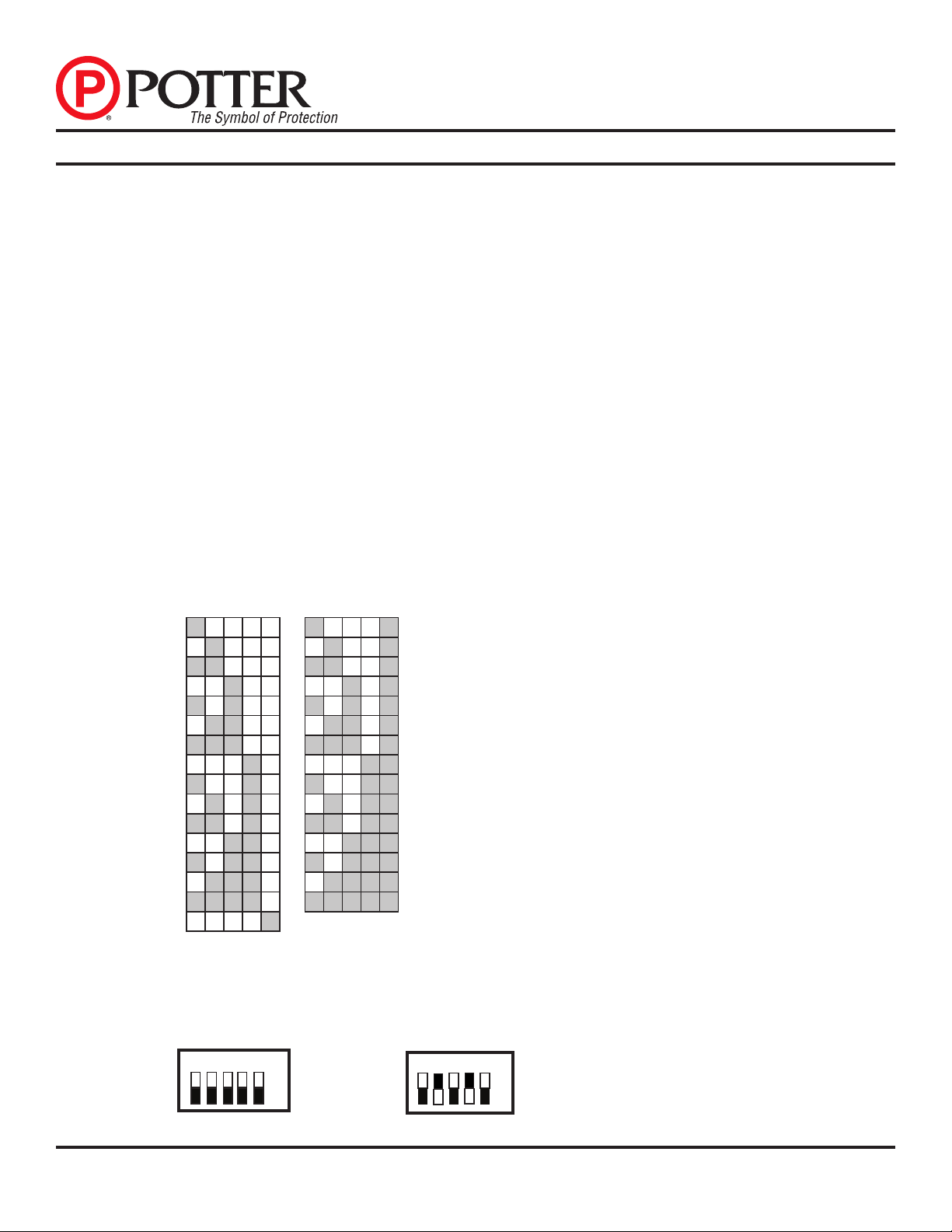
thirty-one (31). The table below may be used to set dip switches when addressing any P-Link module:
FIGuRE 1. DIP SWITCH SETTINGS TABLE (ADDRESSES 1–31) P-LINK DIP SWITCHES ARE LABELED 1,2,3,4,5.
Note: Each “gray” box indicates that the dip switch is “On,” and each “white” box indicates “O.”
The examples shown below illustrate a P-Link’s dip switch settings: the 1st example shows a P-Link module not
ad¬dressed where all dip switch settings are in the default “O” position, the 2nd illustrates an addressed P-Link module
via the dip switch settings
FIGuRE 2. EXAMPLES OF P-LINK MODuLE SHOWING DEFAuLT DIP SWITCH SETTING (uNADDRESSED) & ADDRESSED
Note:Unless these are dierent than other P-Link dip switches they are labeled 1,2,3,4,5 and not 1,2,4,8 &16
124816 124816
11
7
21
8
31
9
42
0
52
1
62
2
72
3
82
4
92
5
10 26
11 27
12 28
13 29
14 30
15 31
16 124
81
6
124816
OFF
ON
1 2 4 16
8All dip switches are
shown in the "O"
position. OFF
ON
1 2 4 16
8Example shows this P-Link module
address = 10. Dip switches #2 & 8
are in the "On" position.

PAGE 2 OF 55409248-REV A 3/23
Potter Electric Signal Company, LLC • St. Louis, MO • Phone: 800-325-3936 • www.pottersignal.com
INSTALLATION MANUAL: LOC-PSN1000
Before connecting a device to the P-Link (RS-485 + Power) connection, take the following precautions to prevent potential
damage to the RS-485 connection or device.
• Power to the RS-485 connection is removed.
• Field wiring on module is correctly installed.
• Field wiring has no open or short circuits.
3. TECHNICAL SPECIFICATIONS
Standby Current 50 mA
Alarm Current 138 mA
Operating Temperature Range 32° to 120° F (0° to 49°C)
Operating Humidity Range 10% to 93% (non-condensing)
4. INSTALLATION
The SCA-5070INT is equipped with a stacker bracket for secure and accessible mounting and can be mounted in the IPA-
4000V, AFC-1000V, LOC-1000 and PSN-1000E. The amplier communicates using a 4-wire Power and RS-485 commu-
nication connection called P-Link. Audio is delivered through the audio riser via V-Link 1. A 15K end of line resistor must
be placed on the last device connected to the V-Link circuit. The SCA-5070INT is required to be powered by a NAC circuit
congured with the Potter Programmer to provide constant 24VDC. All connections are power limited and supervised.
SCA-5070INT: A maximum of 50W per circuit at 25VRMS and 70VRMS.
FIGuRE 3. SCA-5070INT INSTALLATION -SCA-5070INT CONNECTIONS

PAGE 3 OF 55409248-REV A 3/23
Potter Electric Signal Company, LLC • St. Louis, MO • Phone: 800-325-3936 • www.pottersignal.com
INSTALLATION MANUAL:LOC-PSN1000
FIGuRE 4. SCA-5070INT INSTALLATION - IPA-4000V AND LOC-1000 ENCLOSuRE
FIGuRE 5. SCA-5070INT INSTALLATION – PSN-1000E
FIGuRE 6. P-LINK CLASS B WIRING

PAGE 4 OF 55409248-REV A 3/23
Potter Electric Signal Company, LLC • St. Louis, MO • Phone: 800-325-3936 • www.pottersignal.com
INSTALLATION MANUAL: LOC-PSN1000
FIGuRE 7. P-LINK CLASS A WIRING
FIGuRE 8. V-LINK 1 CLASS B WIRING
FIGuRE 9. V-LINK 1 CLASS A WIRING

PAGE 5 OF 55409248-REV A 3/23
Potter Electric Signal Company, LLC • St. Louis, MO • Phone: 800-325-3936 • www.pottersignal.com
INSTALLATION MANUAL:LOC-PSN1000
5. NOTES:
• RS-485 wiring style supports class A and class B.
• RS-485 is power limited
• Wiring for terminals (A, B) and (+,-).
• Wire preparation - strip all wires 1/4 inch from thier edges as shown here:
- Stripping too much insulation may cause a ground fault.
- Stripping too little may cause a poor connection and subsequently an open circuit.
These instructions do not purport to cover all the details or variations in the equipment described, nor provide for
every possible contingency to be met in connection with installation, operation, and maintenance.
Specications subject to change without prior notication.
For Technical Assistance contact Potter Electric Signal Company at 866-956-1211.
Table of contents
Other Potter Amplifier manuals