Power bass Xtreme XEX-23 User manual

3-WAY ELECTRONIC CROSSOVER
Owners Manual
Please read through this manual to familiarize yourself with your new crossover. Should your PowerBass
Xtreme processor ever require service, you will need to have the original dated receipt.
XEX-23


Thank you and Congratulations
Thank you for your decision to purchase a PowerBass USA 3-Way Electronic Crossover. A crossover is a high
fidelity audio device that cuts off, or crosses, different frequencies. The built-in preamplifier stage raises the
signal level of your head unit, and increases the dynamic range of your system. All this is housed in an attrac-
tive brushed black aluminum case with a fully isolated DC to DC power supply.
2/3-WAY ELECTRONIC CROSSOVER
This installation manual contains valuable information on how to get the most out of your new PowerBass
XEX-23 3-Way Electronic Crossover. Designed and engineered using the latest in signal processing technol-
ogy, virtually any car stereo system will benefit from the addition of this unique and versatile product.
∆Caution ∆
High powered audio systems in a vehicle are capable of generating higher than “Live Concert” levels of sound pressure. Continued exposure
to excessively high volume sound levels will cause hearing loss or damage. Also, operation of a motor vehicle while listening to audio equip-
ment at high volume levels may impair your ability to hear external sounds such as horns, warning signals, or emergency vehicles—thus
creating a potential traffic hazard. In the interest of safety, PowerBass USA highly recommends listening at lower volume levels while driving.
CROSSOVER
3

TECHNICAL FEATURES
• 2 or 3-Way Active Electronic Crossover
• Front and Rear x10 Frequency Multiplier Switches
• Tri-Mode Input (Front/Rear/Subwoofer)
• Remote Bass Boost Control
• Overlapping Crossover Design
• 0-180 Degree Subwoofer Phase Control
• Active Band Pass Switch
• Nickel Plated Tiffany Style RCA Jacks
• Single Soure Input Switch
• PWM Power Supply
• LED Power Indicator
• Variable 18dB Bass Boost Circuitry
The PowerBass XEX-23 takes the incoming audio signals and separates them into three distinct frequency
ranges according to the frequency range of the speakers that are going to be amplified. The low (bass) fre-
quencies are directed to the amplifier driving the subwoofer system, the mid/high frequencies to the amplifier
driving the midrange and tweeters. With all the signals outside the pre-selected range filtered out, each of
these amplifiers can then devote their full power to the handling of less complex audio signals, resulting in
cleaner and more accurate musical reproduction.

CONTROL PANEL LAYOUT
1. BATTERY (Power Input Terminal +12V)
To be connected to the positive terminal of the vehicle battery or other constant +12V sources.
2. REMOTE (Remote Turn-On Input Terminals)
To be connected to the remote control wire or antenna lead of the head unit for turn ON/OFF.
3. GROUND (Ground Input Terminal)
To be wired to the vehicle’s chassis (ground).
Power Plug
5

4. POWER Indicator
This indicator lights up blue when the internal power supply is activated and the unit operational.
5. FRONT LINE IN (RCA) JACKS
To be connected to the front channel output of the head unit.
6. INPUT MODE Switch
When the Input Mode switch is set to “FRONT” position, the input signals from head unit and the signal will
be split and directed to the front and rear channels of this crossover network simultaneously. (This feature is
to be engaged where the head unit has no separate Front/Rear Outputs and the fader control from head unit
will not be able to control for fading the signal level from front to rear channels.)
7. REAR LINE IN (RCA) JACKS
To be connected to the rear channel outputs of the head unit for fading capabilities.
8. SUBWOOFER INPUT Switch
If your head unit has no subwoofer output(s) this switch should be at the “FRONT” position to allow the signal
from the front/rear channels supply to the subwoofer input selection of the crossover.
9. SUBWOOFER LINE IN (RCA) JACKS
To be connected to the subwoofer channel output(s) of the head unit (if applicable).
*Please make sure that the “Subwoofer Input” switch is set to the “SUB” position.
10. Front Channel HIGH - PASS Frequency Control
For the selection of the front channel high-pass crossover frequency between 30Hz and 500Hz (300Hz and
5kHz when the “Multiplier” switch is at “x10” position).
11. Rear Channel HIGH PASS Frequency Control
Same as 10 but for rear channel only.
12. Subwoofer LOW PASS Frequency Control
For the selection of the low-pass crossover frequency for the subwoofer channel from 30Hz and 500Hz.
13/14. Front/Rear FREQUENCY MULTIPLIER Switch
Positioning this switch at the “x10” range allows the selectable crossover frequency change for the front
and/or rear channel high-pass from 30Hz - 500Hz to 300Hz - 5kHz.

15. BANDPASS Switch
To allow the front channel signal from head unit to run as active 3-way crossover. It will send the low pass
crossover frequency signal to rear channel input selection of the crossover and therefore you may select the
high pass frequency to run an active bandpass from HP/BP outputs.
16. Front Channel OUTPUT LEVEL Control
for adjusting the front channel outputs signal level.
17. FRONT LINE OUT (RCA) JACKS
To be connected to the front channel left/right amplifier inputs.
18. Rear Channel/Band-Pass OUTPUT LEVEL Control
For adjusting the rear channel/band-pass signal level concidered to the “Band Pass” switch.
19. REAR LINE OUT (RCA) JACKS
To be connected to the rear channel left/right or the band-pass amplifier inputs considered to the “Band-
Pass” switch.
20. PHASE Inverter Switch
Positioning the switch to the “0 degree” the subwoofer output signal in phase with the front/rear output
signals, to the “180 degree” will be out-of-phase relative to the front/rear output signals depending on the
sound from your system in the vehicle.
21. Subwoofer OUTPUT LEVEL Control
For adjusting the subwoofer channel output signal level.
22. SUBWOOFER LINE OUT (RCA) JACKS
To be connected to the subwoofer amplifier inputs.
23. BASS BOOST LEVEL Control
For adjusting the level of amplifier on the signal at 45Hz up to 18dB to the subwoofer signal outputs.
24. REMOTE Port for Bass Boost Control
This is the connector port for the Remote Bass Boost. Allows the crossover’s Bass Boost circuit to be
adjusted from the drivers seat.
Note: Plugging in the Remote Bass Boost Control overrides the Bass Boost Level Control on the
XEX-23 chassis.
7

INSTALLATION EXPERIENCE
Installation of PowerBass mobile sound equipment requires detailed knowledge of electronics wiring and
proper speaker impedance. We strongly recommend installation by an authorized PowerBass Xtreme dealer.
This Owner’s Manual only provides general installation and operation instructions. If you have any reservations
about your installation skills, please contact your local PowerBass dealer for assistance.
PREPARING FOR INSTALLATION
NOTE: The tools listed below may be required for basic installation
• An electric drill with bits
• Philips head and standard screwdrivers
• Wire strippers
• Crimping tool
• VOM (electronic volt ohm meter)
• Heat shrink tubing and heat gun
• Soldering iron
INSTALLATION SEQUENCE
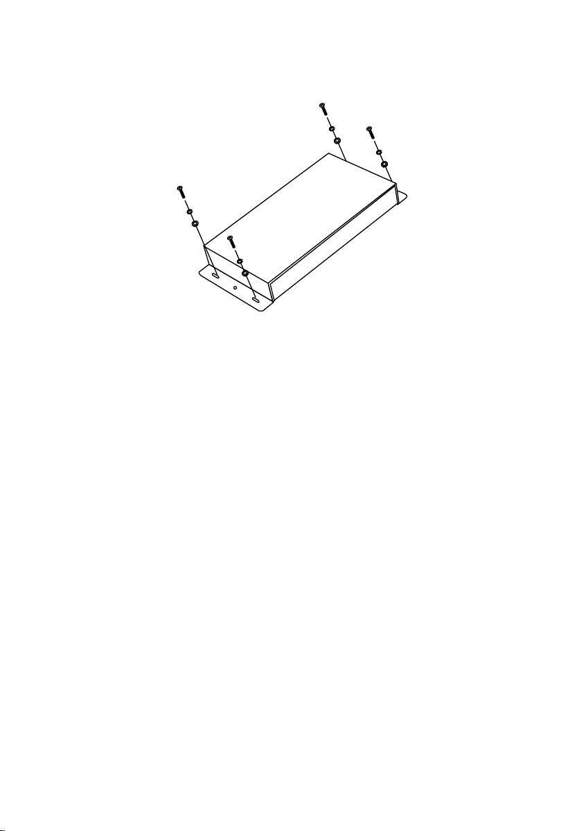
1. Find a suitable location in the vehicle to mount the crossover. Do not mount the crossover
directly to the chassis, or any metal part, of the vehicle to ensure maximum noise rejection.
2. Bolt the crossover to the mounting surface, and make sure the mounting screws do not
touch any metal part of the vehicle to ensure maximum noise rejection.
3. Using the Power Plug provided connect 16 gauge, wire for Power, Ground and Remote turn
on signal, making sure to connect the Power and Ground to the proper location on the power
plug. Run 16 gauge, ground wire from the chassis of the head unit to the ground of the
crossover. The Power should be made directly to the (+)12 voltvehicle battery, or power
distribution point. The Remote should be connected via relay to the Remote Turn On lead
of your head unit (radio).
4. Connect all line inputs and outputs using high quality RCA interconnects.
5. Re-check all connections before powering the unit on.
6. Set all level controls to their minimum positions. Set all crossover points and switches to
the desired frequencies and positions.
7. Once the system is powered on, set the volume control on the head unit to 80% of maximum,
then set level controls on the crossover.
8. Further tuning of the controls may be necessary to obtain the desired results.

To keep your PowerBass Electronic Crossover running at top performance, choosing the proper location is of
utmost importance. The crossover should also be protected from exposure to moisture and direct sunlight.
The best place to mount your crossover is a convenient location which will allow access to the inputs and other
variable controls. Be sure that the power and signal cable connections can enter and leave the crossover in a
straight line to avoid the risk of kinked wires causing malfunction.
You may use the crossover as a template and mark the four screw locations with a felt tip pen. Use caution
to make sure there are no objects behind the installation surface that may become damaged during drilling.
Power Wiring and Signal Connections
The potential of your XEX-23 crossover is unlimited. When mated with our PowerBass amplifiers, subwoofers
and separates the XEX-23 can deliver sonic reproduction that rivals a live performance. The following pages
give just a few examples of popular system configurations; however you are not limited to just these. For
more exotic system layouts, consult with your local PvowerBass Xtreme dealer.
Be extra careful when routing your RCA audio interconnect cables. Car environments are notorious for poorly
insulated wires. This means that hiss, engine noise, and fan noise can easily be picked up through RCA
cables if run incorrectly.
Make sure that the cables for power and audio signal are not on the same side of the vehicle and that they
do no cross each other; this will help reduce any noise that may radiate from the power cable and the signal
cable. If an audio cable is too close to a power cable, it may pick up the magnetic field generated by the
power cable, which could lead to a loss of quality in your signal.
If RCA interconnects must cross power cables, noise can best be avoided by crossing them
between 45° and 75°.
MOUNTING THE CROSSOVER
9

MIN MA X
Remote Bass Knob
Input Side
Output Side
Power Connections: Use the convenient Power Plug to wire up the Power, Ground and Remote Turn-on as
follows: BATTERY+: Insert an 16 gauge or larger wire into the plug for the 12 volt (+) position. He
other end should be connected to a good, fused, constant 12V DC positive source.
REMOTE: Connect a 22 to 16 gauge wire from the Radio’s (head unit) remote turn-on
lead.
GROUND: Use the same gauge wire as you did for the positive connection and run it from
the “Ground” connector to a single ground (-) location point where the amplifiers are also
grounded.
Once you have completed wiring the Power Plug, gently push it into the socket on the side panel of the
PowerBass XEX-23.
POWER CONNECTION
Power Plug
Choose the correct length and style of RCA interconnects for your needs (not included). Run the RCA cables
from the head unit to the location of the PowerBass XEX-23. Make sure all the RCA cables are run on the
opposite side of the vehicle from where you ran the power cables to the amplifier(s). Hiss, engine noise, and
fan noise can easily be picked up through the RCA cables if run incorrectly.
Attach the RCA cable from the amplifier(s) to the OUTPUT jacks on the side panel of the processor.
RCA INTERCONNECTS

SYSTEM DIAGRAMS
1. Using One Pair of Inputs
When only one pair of inputs is available, input the signal to the FRONT input section and set
the SUBWOOFER INPUT switch to FRONT and the INPUT MODE switch to FRONT. This will
allow the signals to be fed internally to the SUBWOOFER and REAR sections to give proper
results. The FREQUENCY MULTIPLIER switch should be in the X1 position on both FRONT and
REAR.
2-channel amp for FRONT
2-channel amp for REAR
mono amp for SUBWOOFER
IMPORTANT: Correctly set the switches as shown in the diagrams below.
11

4-channel amp for FRONT and REAR
mono amp for SUBWOOFER
5-channel amp
IMPORTANT: Correctly set the switches as shown in the diagrams below.

2. Using Two Pair of Inputs
When front and rear pairs of inputs are available input the signals into the FRONT and REAR
inputs, respectively. Set the SUBWOOFER INPUT switch to the FRONT position to allow the
signals to be fed internally to the SUBWOOFER section to give proper outputs and set the
INPUT MODE switch to FRONT/REAR to allow the head unit to control the fader. The FRE-
QUENCY MULTIPLIER switch should be in the X1 position on both FRONT and REAR.
2-channel amp for FRONT
2-channel amp for REAR
mono amp for SUBWOOFER
IMPORTANT: Correctly set the switches as shown in the diagrams below.
13

3. Using Three Pair of Inputs
All three pair of inputs on the XEX-23 can be utilized when front, rear and subwoofer outputs
are present on the source unit (radio/ CD). Set the SUBWOOFER INPUT to the SUB position
to allow independent subwoofer level control from the source unit. Set the INPUT MODE
switch to the FRONT/REAR position to allow the source unit to control fader. Please Note:
Some source units offer independent control of the subwoofer/non-fader output
signal. The FREQUENCY MULTIPLIER switch should be in the X1 position on both FRONT
and REAR.
2-channel amp for FRONT
2-channel amp for REAR
mono amp for SUBWOOFER
IMPORTANT: Correctly set the switches as shown in the diagrams below.

4. 2-Way Front Stage Setup
When you are bi-amping the front stage (amplifying the mid-range and tweeter separately)
you will need to setup the crossover differently. On the FRONT set the FREQUENCY MULT-
PLIER switch to X10 and the BANDPASS switch to ON. Set the INPUT MODE to FRONT. You
will only use the FRONT inputs. The FREQUENCY MULTIPLIER switch multiplies the cross-
over frequencies by 10, so instead of crossing from 30 Hz to 500 Hz, it will cross from 300
Hz to 5 kHz. On the REAR section the FREQUENCY MULTIPLIER will need to stay at the X1
position. The SUBWOOFER INPUT will be set at above, depending on whether you are using
a subwoofer input signal or not.
2-channel amp for FRONT tweeters
2-channel amp for REAR mid range
mono amp for SUBWOOFER
IMPORTANT: Correctly set the switches as shown in the diagrams below.
15

TUNING YOUR XEX-23
SETTING THE CROSSOVER POINT FOR THE SUBWOOFER OUTPUT SECTION
• After installation of your XEX-23, amplifiers and speakers start turning output level controls
to the minimum position, all HIGH PASS controls to the maximum position and all LOW PASS
controls to minimum position. All amplifier gain levels should be at the minimum position
and all crossovers should be off. If there is no off position, if the amplifier is for high pass
the crossover should be in the minimum position. Conversely, if the amplifier is to be used
for low pass the crossover should be in the maximum position. For subwoofers, the sub-
sonic filter may still be used, if available.
• Set the desired CROSSOVER FREQUENCY for the SUBWOOFER output using your LOW PASS
dial. You may select from 30 Hz to 500 Hz as your crossover point. Most systems should
be crossed between 30 Hz and 120 Hz.
• Set the BASS BOOST by using the BASS BOOST LEVEL dial to set the boost gain from 0 dB
to +18 dB. The BASS BOOST center frequency is 45 Hz.
• Select the PHASE of the subwoofer using the PHASE switch, 0 degrees or 180 degrees.
Most systems will use the 0 degrees setting.
2-channel amp for FRONT tweeters
2-channel amp for REAR mid range
mono amp for SUBWOOFER
IMPORTANT: Correctly set the switches as shown in the diagrams below.

SETTING THE CROSSOVER POINT FOR THE REAR (MIDRANGE) OUTPUT
Usually the MID output is a BANDPASS design. It is achieved by setting the BANDPASS switch to
ON and using both BP HIGH PASS and BP LOW PASS dials. The BP LOW PASS dial will set the
lower frequency limit for the midrange speaker. The BP HIGH PASS will set the upper frequency
limit for the midrange (on the REAR output) AND the lower frequency limit for the tweeter (on
the FRONT output). Set the desired BP LOW PASS frequency to set the lower frequency limit for
the midrange between 30 Hz and 500 Hz, or, using the MULTIPLIER SWITCH, between 300 Hz
and 5 kHz. This will typically be set at the same frequency you set the SUBWOOFER LOW PASS
frequency.
SETTING THE CROSSOVER POINT FOR THE FRONT (HIGH) OUTPUT
• Set the desired frequency cutoff using the HIGH PASS dial for your HIGH output, such as
tweeters. The FREQUENCY MULTIPLIER switch must be set to X10, as most tweeters cannot
safely operate at less than 3kHz. This will allow you to cross the output between 300 Hz
and 5 kHz.
• You also have the option of running midbass or midrange level in the FRONT by using the
frequency range from 30 Hz to 500 Hz with the FREQUENCY MULTIPLIER switch set to X1.
FINE TUNING YOUR SYSTEM
One very important part of fine tuning your system is properly level matching the signal from the
source unit to the XEX-23 crossover and from the crossover to the amplifiers. Level matching
is the process of calibrating the audio signal from the Source unit all the way to the amplifiers
to eliminate unwanted noise and maximize the dynamic headroom. When the system is properly
adjusted you should achieve maximum output before distortion at about 80% volume on the
source unit.
17

MATCHING THE SIGNAL LEVEL
(Note: If you have a pre-amp equalizer in the system or built in to the source unit, bypass or turn
off the equalization while level matching)
1. Turn all three output level dials on the XEX-23 (SUBWOOFER, REAR and FRONT) to maximum
position.
2. Turn the BASS BOOST level on the XEX-23 and the amplifier to minimum.
3. Turn all input sensitivity gain control adjustments on the amplifiers to the minimum position.
4. Turn on the system and increase the source unit’s volume to 80% of maximum.
5. VERY SLOWLY increase the input sensitivity gain on each amplifier to the point right before
the speakers begin to distort. Use CAUTION not to overdrive the speakers. Do this for all
three amplifiers, one by one, starting with the tweeter amplifier.
Once all adjustments are made the system should sound clear without distortion up to 80% of
main volume. Also, the volume should increase very evenly. We only use up to 80% of maximum
volume on the source unit because after this point most source units begin to distort the signal.
If you want your system louder you will need to get more powerful amplifiers.
ADJUSTING OVERALL BALANCE OF THE SYSTEM
Once you complete the signal matching stage the following steps should be made to set the
overall linearity of the system. This may be necessary due to the relative efficiencies of each of
the speakers. For example, smaller speakers are normally more efficient than woofers, and play
louder sooner, at given equal power levels. The XEX-23’s individual output level controls allow
compensation for this.
It is important to understand that the output levels are not designed to add gain to the signal.
Actually, the output level controls attenuate (reduce signal gain). It is for this reason that in the
following steps we will start with the output levels at the maximum position, and then reduce
the outputs to balance the system. For example, if you like heavy bass you will most likely leave
the SUBWOOFER OUTPUT LEVEL at the maximum position, and reduce the MID and HIGH output
levels by, up to, half. This will allow the bass to reach a high output faster than the MID and
HIGH speakers. If you wish to increase the MID and HIGH frequencies, reduce the SUBWOOFER
OUTPUT LEVEL. You should make these adjustments to your liking. This means tune your system
so it sounds best to YOUR ears. After all, this is YOUR system.
You are now ready to enjoy your audio system.

Your PowerBass XEX-23 includes a remote Bass Boost Control. It uses standard 6-pin telephone wire and
modular (U.S.A. style) telephone connectors. To connect the remote Bass Boost Control to the crossover,
simply insert one end of the telephone plug into the REMOTE GAIN port. Plug the other end into the remote
module. Install the module within easy reach on or under your dash.
Note: Plugging in the Remote Bass Boost Control overrides the Bass Boost Level Control on the
XEX-23 chassis.
Notes:
Once the optimum crossover frequencies and output levels are located, mark them down on the chart below
for future reference in case the settings are accidentally changed.
Front Frequency Selector: __________________Hz
Front Frequency Multiplier: x_________________
Rear Frequency Selector: __________________Hz
Rear Frequency Multiplier: x_________________
Bandpass: _________________________ ON or OFF
Subwoofer Input: __________________ SUB or FRONT
Subwoofer Frequency Selector: __________________Hz
Front Output Level: ______________________(o’clock position)
Rear Output Level: ______________________(o’clock position)
Subwoofer Output Level: ______________________(o’clock position)
Remote Gain Controller Connection
19

TROUBLESHOOTING TIPS
Problem Solution
No Sound 1. Check “Power” and remote turn-on for proper volt-
age and wiring position.
2. Center the Fader Control
3. Turn up the “Input Gain” controls
4. Check the Ground connections
5. Push the “Source” button
Hiss 1. Turn down the amplifier gains
2. Adjust the Source unit output
3. Check for kinked or faulty RCA interconnect cables
Distorting Speakers 1. Adjust the equalization levels
2. Adjust gain levels
3. Lower the volume of the Source unit
4. See your Dealer
Table of contents