Power Innovations INVB Series Parts list manual

Version 5.3/November 2011
1
Inverter
INVB-Series
for
Telecom, Industry and
Rail Applications
Technical Description –English

PRODUCT DESCRIPTION
2
Manufacturer’s Address:
Power Innovation Stromversorgungstechnik GmbH
Rehland 2
28832 Achim
Germany
Tel.: +49-(0)4202-5117-0
Fax.: +49-(0)4202-5117-70
e-mail: [email protected]
web: www.powerinnovation.com
All information and data in this manual correspond to the momentary state
of technology which applies at time of press.
Furthermore we do not take any guarantee for these documents referring
to appliance or interpretation. This does not alter the manufacturer's guar-
antee on power supplies. Our general business terms apply as well as the
terms of the "Zentralverband der Elektrotechnischen Industrie e.V.
(ZVEI)".
Any form of partial or complete reproduction or translation of this manual
may only be done with explicit authorization by Power Innovation GmbH.
We reserve the right to implement modifications without prior notice in line
with technical developments and/or manufacturing techniques.
Version 5.3
Printed in Germany
© Copyright Power Innovation GmbH 2011

PRODUCT DESCRIPTION
3
Contents
1Preface...................................................................................................................... 4
2Acceptance test......................................................................................................... 5
2.1 Checking for damages........................................................................................ 5
3Installation ................................................................................................................. 6
3.1 Operational environment .................................................................................... 6
3.2 Safety requirements ........................................................................................... 7
3.3 External fusing.................................................................................................... 7
3.4 Electrical connections......................................................................................... 7
3.5 Device protection................................................................................................ 7
3.6 Grounding........................................................................................................... 7
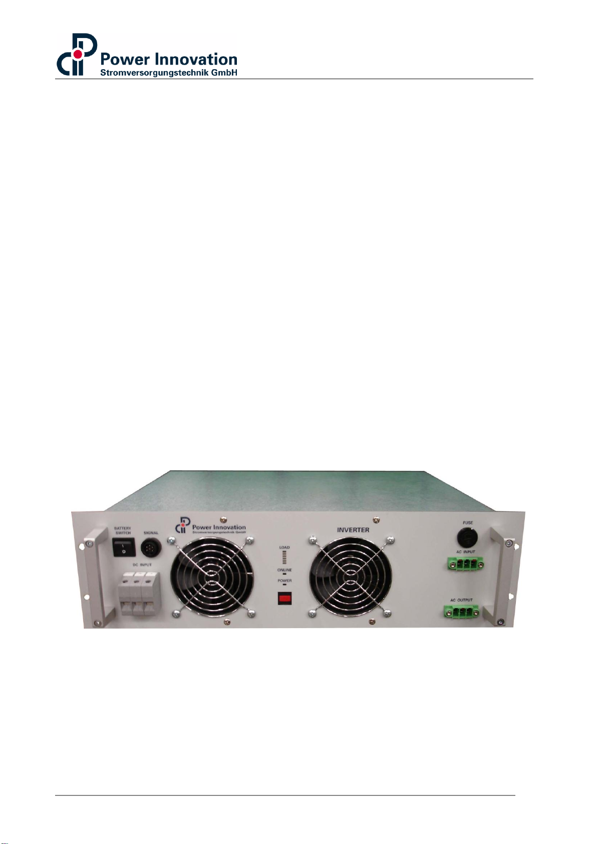
3.7 Product description............................................................................................. 9
3.8 Control elements and connections ................................................................... 11
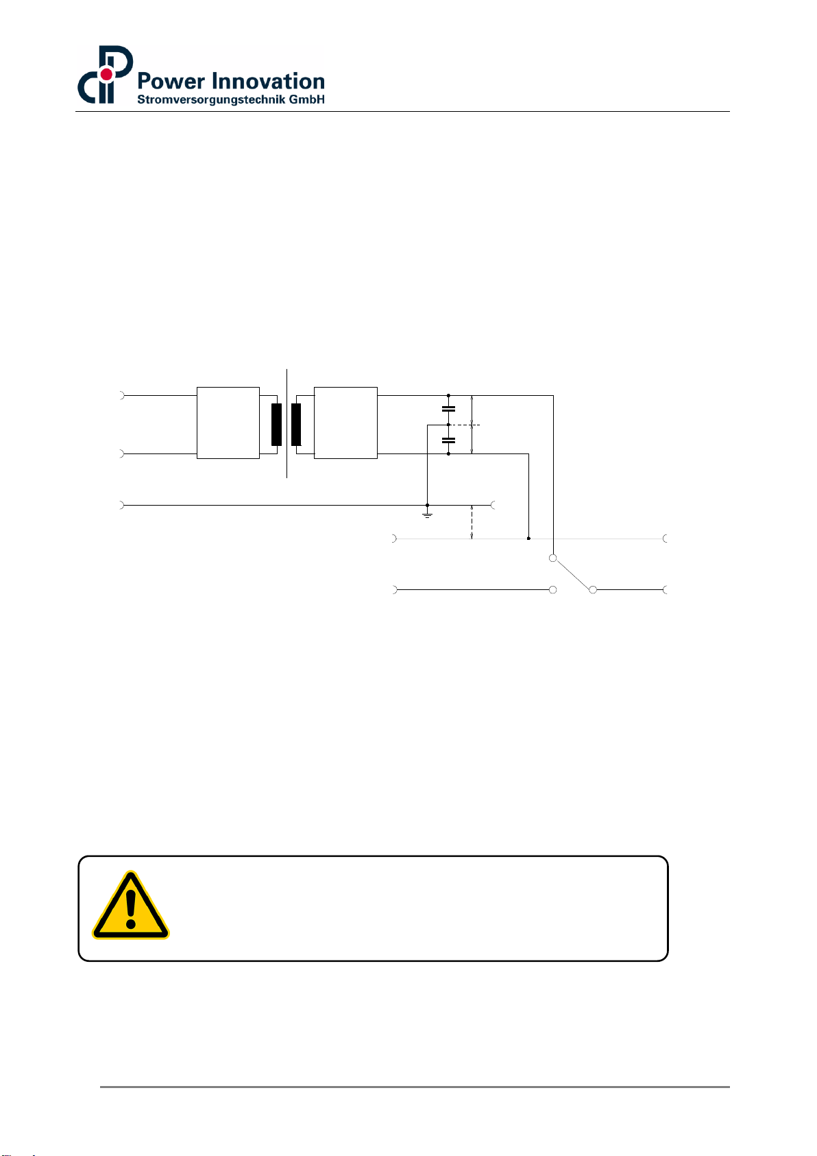
3.9 Block diagram................................................................................................... 12
3.10 Fuse ................................................................................................................. 12
3.11 Connection ....................................................................................................... 13
3.11.1 VDC input.................................................................................................. 13
3.11.2 LED display............................................................................................... 14
3.11.3 Mode Changeover..................................................................................... 14
3.11.4 Alarm contact ............................................................................................ 15
3.11.5 AC input/output.......................................................................................... 16
3.12 Operation.......................................................................................................... 17
3.12.1 Prerequisites ............................................................................................. 18
3.12.2 Operation with external commercial power line (mains)............................ 18
3.12.3 Bypass switching characteristics............................................................... 19
4Setup....................................................................................................................... 20
4.1 Enabling setup mode........................................................................................ 20
5Mechanical dimensions ........................................................................................... 22
6Exhibit...................................................................................................................... 23
A. Conversion table AWG to millimeter........................................................................... 23
B. Declaration of conformity............................................................................................ 24
C. Technical data............................................................................................................ 25
D. Fields of application.................................................................................................... 26
E. Applications................................................................................................................ 26
F. Shipping and storage.................................................................................................. 26
G. Terms of warranty...................................................................................................... 27

PRODUCT DESCRIPTION
4
1 Preface
Dear customer!
Thank you for purchasing a product from Power Innovation GmbH.
This manual contains detailed information about the Power Innovation GmbH device you
purchased. It describes the features, basic functions, various applications and offers so-
lutions in case of failure. Instructions on installation, storage and shipping are also in-
cluded.
Please note that this manual contains the description of an entire series of Power Innova-
tion products. Please check your order and/or device label in order to refer to the corre-
sponding information given in this manual.
This manual addresses mostly to chief operators and system supervisors, electrical con-
sultants and installation electricians. Our devices may only be installed by qualified per-
sonnel, according to the following instructions as well as national and international regu-
lations where applicable.
Our products’ technology meets all requirements of telecommunications, electric power
supply, industry and others. Our product line ranges from small power inverters to large
inverter systems.
State of the art circuit design delivers high efficiency. This allows long term operation at
low temperature stress. The devices need no servicing.

PRODUCT DESCRIPTION
5
2 Acceptance test
2.1 Checking for damages
Power Innovation products are manufactured and shipped according to strict quality con-
trol standards. If a product proves to be defective in material or workmanship, the warran-
ty will be granted (refer to our “Terms of Warranty”).
Check the product for damage due to shipment. In case of damage,
keep all packing material for further examination.
If you discover shipping damage after inspection, you must submit a
claim for covered shipping damage.
Inform the forwarder of shipping damage by sending a fax immediately.
Send a copy of the damage claim to Power Innovation GmbH immedi-
ately.
The manufacturer will not be liable for any injury, loss or damage, arising directly or con-
sequentially out of the improper use of this product. It is mandatory to read this manual.
Please observe all printed instructions, especially the safety advices.
Please note:
In case of claims, please refer to your specific product informa-
tion, such as serial number, input and output voltages, as shown
on the device label.

PRODUCT DESCRIPTION
6
3 Installation
3.1 Operational environment
All the requirements concerning environment described in this chapter must be fulfilled.
When planning on location and installing the device the following points must be consid-
ered:
For correct function and optimal life span avoid temperature and humidity
peaks (non condensing environment).
Make sure that proper ventilation is guaranteed.
With forced cooling devices, ensure that cooling air is able to flow unhin-
dered through the front side and the rear side of the inverter (clearance
between the front side and rear side min. 150 mm).
Upon disregard of the above hints, Power Innovation GmbH can neither guarantee the
safety of personnel involved nor a correct function of the power supply.
Caution:
Do not operate the inverters in explosive areas. Operation of
the inverters in such an environment constitutes a safety
hazard. Furthermore, the inverters must not be operated in
hermetically sealed cabinets.
Note:
The electrical planning and installation of the device may
only be undertaken by qualified personnel. It must comply
with all local legislation and regulations.
The installation instructions must be followed carefully. If ne-
glected, safety and health of the personnel involved are
threatened and injuries and/or fatality may be caused.
Please refer to your country’s regulations.

PRODUCT DESCRIPTION
7
3.2 Safety requirements
Explanation of the safety symbols used in this manual:
The electrical planning and installation of the device may only be undertaken by qualified
personnel. It must comply with all local legislation and regulations. The installation in-
structions must be followed carefully. If neglected, safety and health of the personnel in-
volved are threatened and injuries or fatality may be caused. Furthermore, the device or
connected load may be damaged. All wiring must be done in a voltage free state in order
to avoid any damage to life and equipment. Make sure that wiring diameters meet the
specified system current from/to the device, if applicable. Please refer to your country’s
regulations.
3.3 External fusing
For maintenance and especially for safety reasons, external fusing for DC supply, AC
supply and AC output must be provided. It is strongly recommended to use 2-pole circuit
breakers for both DC and AC fusing.
3.4 Electrical connections
When connecting the inverter, ensure the correct cable size and diameters. Please find
additional information printed in the section 3.7 Control elements and connections.
3.5 Device protection
It is recommended using additional mounting rails to support the sub-rack inside the
frame / cabinet. Please contact your cabinet manufacturer for a suitable rail.
3.6 Grounding
Ensure a correct ground connection. The ground contact (PE) must be connected to the
DC input of the device, using the largest possible diameter. Furthermore, for all wall
mounted devices, connect the PE to the ground bolt, if applicable.
The inverter, manufactured by Power Innovation GmbH, has a galvanic isolation between
DC input and AC output. The generated AC output voltage (230VAC/ 50 Hz) is electrically
isolated from the DC input and the protective earth (PE)/mechanical housing.
Warning
Caution
Warning Ex-
plosion
Warning:
Do not open the device! Some components insides carry high
voltages. Disregard threatens the safety and health of personnel
involved and may cause injuries or even fatality. There are no
maintenance points inside the inverter.

PRODUCT DESCRIPTION
8
The only connection is a capacitive connection via the EMC Y-capacitors to the mechani-
cal housing. These capacitors are necessary to fulfil the EMC requirements. The electri-
cal capacity of these Y-caps is < 10 nF and the leakage current is < 2,5 mA. The inverter
fulfills international norms and is marked with the CE label.
For inverters with integrated bypass switch, which means for inverters providing an AC
input fed by the commercial power line (mains), the commercial power line N-wire is
linked straight to the AC output of the inverter. Therefore the output potential of the in-
verter is electrically tied to N, even during inverter operation mode. For inverters with in-
tegrated bypass switch we recommend the correct (phase correct) connection to the
commercial power line (mains). The isolation to the mechanical housing and the DC input
is still there. See figure 1 for reference.
Figure 1
Attention:
If an inverter with integrated bypass switch is used without the AC input connected to the
commercial power line, the AC output is a floating output again. The N pole of the AC
input connector at the inverter is tied to the floating potential again, caused by the EMC
capacitive voltage divider (Y-capacitors). An AC input which is not used shall be protect-
ed by the supplied AC input connector (appliance connector) or by a sufficient cover. You
can use the supplied AC input connector as a “blind connector”
DC-IN Inverter
Output
Isolation
Y-c ~ 10 nF
PE
1/2 Vout
Y-c ~ 10 nF 1/2 Vout
AC-IN
N
L
AC-OUT
N
L
Bypass
Switch
DC-Voltage
PE
+
-
Attention:
In-phase connection required!
Generally, a fixed installation is required.
(A grounding type plug must not be used!!!)

PRODUCT DESCRIPTION
9
3.7 Product description
The inverters of the INVB series are described as follows:
Power rating and voltage versions:
Product
Power rating
DC-Input Voltage
AC-Output Voltage
INVB4000
4000 VA/3200 W
48/60, 110, 220VDC
230VAC, 50 Hz
INVB2000
2000 VA/1600 W
48/60, 110, 220VDC
115VAC, 60 Hz
Table 1
Please note:
The following chapters describe technical features and data that
may depend on power version, voltage version or options or-
dered. If not otherwise mentioned, any information given in these
chapters refer to all the series’ products. Please check your or-
der and/or device label in order to refer to the corresponding in-
formation given.
Warning:
Do not open the device! Some components insides carry high
voltages. Disregard threatens the safety and health of personnel
involved and may cause injuries or even fatality. There are no
maintenance points inside the inverter.

PRODUCT DESCRIPTION
10
The inverters of the INVB series have an integrated bypass switch module. The inverter
is a pure stand alone operating unit and has no parallel operating functionality. The in-
verter can operate either in the ON-Line (load is preferably supplied by the inverter line)
or in the OFF-Line (load is preferably supplied by the commercial power line) operation
mode. The switch-over time of the integrated bypass contact is less than 4 ms.
The inverters of the INVB series are forced fan cooled (the speed of the internal fan is
depending on the internal inverter temperature and the AC output power).
Our inverters offer the following protective and monitoring functions:
a) Overload- and short circuit protected output
b) DC UVP (under voltage protection) and DC OVP (over voltage protection)
c) AC UVP/OVP at the inverter output
d) AC UVP/OVP at the mains input
e) Protection against excess temperature
f) Frequency monitoring (fixed +/- 3 Hz tolerance range)
g) Protection from reverse connection of the battery

PRODUCT DESCRIPTION
11
3.8 Control elements and connections
Inverter INVB4000/INVB2000 in 48/60, 110 and 220VDC.
Figure 2
No.
Description
Type
1
AC input, 1-phase commer-
cial power line (mains)
Phoenix Power Combicon
2
AC output, 1-phase,
Phoenix Power Combicon
3
AC input fuse
Commercial power line (mains) input L
4
Control push button
Push button for setup and control settings
5
LED
2+6 Bargraph
6
Input voltage DC
Phoenix HDFK 16 screw clamps, 16mm2
7
Potential free alarm contact
Binder 6pol. 0,75mm2 250V/3AAC; DC 300V/0,1A;
DC100V/0,2A; DC30V/1A
8
Battery switch
Turns the inverter ON/OFF
Table 2
1
2
3
4
5
6
7
8

PRODUCT DESCRIPTION
12
3.9 Block diagram
Figure 3
3.10 Fuse
The integrated electronic bypass switch of the INVB inverters has one fuse in the AC in-
put line, F1. This fuse is implemented as a protection of the inverter bypass switch and
the electrical contacts used. Even if these fuses protect the commercial power line path
to the inverter AC input in case of a short circuit condition on the load circuit side, the ad-
ditional external fusing with automatic circuit breaker is recommended to switch the in-
verter voltage free for installation or maintenance purposes.

PRODUCT DESCRIPTION
13
3.11 Connection
3.11.1 VDC input
Inverter with 48/60, 110 and 220VDC input
Figure 4
Pin
Function
Abbreviation
1
Input voltage reference
0V Uin
2
Ground wire
PE
3
Input voltage positive
+ Uin
Table 3, DC IN: 3x HDFK 16mm²
1
2
3

PRODUCT DESCRIPTION
14
3.11.2 LED display
Load display
LED 6 (red) 150% overload
LED 5 (red) 125% overload
LED 4 (green) 100% load
LED 3 (green) 75% load
LED 2 (green) 50% load
LED 1 (green) 25% load
Online display
Online LED green Signalizes Inverter operation
Online LED red Signalizes Mains operation
Power display
Power-LED orange Standby mode
Power-LED green flashes Selftest
Power-LED green Normal operation
Power-LED red Internal failure
Power-LED red flashes Setup failure
Power-LED off Inverter is off / no DC supply
Push button
For operation/standby mode switching and Setup setting
(Please refer to chapter 4 Setup).
3.11.3 Mode Changeover
By shortly pressing the pushbutton the Online LED shows the stored operation mode.
Green = normal-inverter, Red = normal-mains mode.
By long pressing, after 3 sec. the operation will be changed and displayed. The new
mode is stored permanently.

PRODUCT DESCRIPTION
15
3.11.4 Alarm contact
Figure 5
Pin
Inverter
Abbreviation
1
Bypass status “Inverter operation mode”
Inverter / NC
2
C (Common)
C
3
Bypass status “Mains operation mode”
Mains / NO
4
Power Good (normal closed)
Inverter o.k. / NO
5
Common
Alarm C
6
Alarm (normal open)
Inverter alarm / NC
Table 4
1
2
3
4
5
6
1
2
3
4
56
Relay 1 (PG/Alarm)
Relay 2 (operation mode)
PG
COM
Alarm
MAINS
COM
INV

PRODUCT DESCRIPTION
16
3.11.5 AC input/output
Figure 6
Figure 7
* Note:
If the external commercial power line is not connected, the inverter output is floating
(see chapter 3.5 Grounding).
Pin
Function
Abbreviation
1
AC in, = 1,5mm²
N
2
Ground wire,
= 1,5 –2,5mm²
PE
3
AC in, = 1,5mm²
L
Table 5, AC input IEC appliance connector, 3-pole, male
Pin
Function
Abbreviation
4
AC out, = 1,5mm²
N *
5
Ground wire,
= 1,5 –2,5mm²
PE
6
AC out, = 1,5mm²
L*
Table 6, AC output appliance connector, 3-pole, female
4
6
5
3
2
N
L
N
L
PE
PE
1

PRODUCT DESCRIPTION
17
3.12 Operation
Note:
The following chapters describe technical features and data that
may depend on power version, voltage version or options or-
dered. If not otherwise mentioned, any information given in these
chapters refer to all the series’ products. Please check your or-
der and/or device label in order to refer to the corresponding in-
formation given.
Caution:
Do not open the device! Some components insides carry high
voltages. Disregard threatens the safety and health of personnel
involved and may cause injuries or even fatality. There are no
maintenance points inside the inverter.
Caution:
The inverters of the INVB series can only operate as stand alone
units. The inverter output is „floating“, when the AC input is not
connected to the external commercial power line. If the external
mains are connected, the inverter output has an L/N/PE
configuration. Observe the polarity (L/N) of the external mains,
when connecting them to the inverter AC input. The neutral (N)
and the protective earth (PE) wires are straightly connected. The
L (Phase) is switched by the internal bypass. (See chapter 3.7
Control elements and chapter 3.8 Block Diagramm.)

PRODUCT DESCRIPTION
18
3.12.1 Prerequisites
Before switching on the device(s), make sure that the following conditions are given:
Ensure that all external fusing (DC input and AC input) is set to 0 (OFF)
Ensure that the BATTERY SWITCH is set to 0 (OFF)
Ensure correct polarity of all connections
Control fastening of all connectors
Switch on the external DC supply by setting the fuse(s) to 1 (ON) position
Switch on the external AC supply (mains) by setting the fuse to 1 (ON)
Position
3.12.2 Operation with external commercial power line (mains)
When the inverter is only supplied by the commercial power line (mains), the internal by-
pass switch stays in the operation mode “Mains supply/OFF-Line operation”. This func-
tion guarantees a load supply, until the DC supply is connected, i.e. later planning of a
battery backup.
When both sources (commercial power line and DC supply) are connected to the invert-
er, the user can choose the mode of operation (ON-Line/OFF-Line). See chapter 3.10.3
Alteration of parameters for setting the bypass operation mode required.
Caution:
The inverter’s AC output carries voltage as soon as the external
AC supply is connected to the AC input of the inverter –even if
no DC input is connected.

PRODUCT DESCRIPTION
19
3.12.3 Bypass switching characteristics
The switch over time of the bypass switch is typical 4ms. If the inverter is set to ON-LINE
mode operation (preferred load supply by the inverter) and e.g. a DC failure occurs, the
bypass switch turns over to mains supply in less than typical 4ms. After reaching a
steady DC supply, the bypass switches back to inverter operation mode. The bypass
needs about 10 seconds to switch back. During that time the bypass checks the stability
of the supply.
If the inverter is set to OFF-LINE mode operation (preferred load supply by the mains)
and a mains failure occurs, the bypass switch turns over to inverter supply in <4ms. After
reaching a steady mains supply again, the bypass switches back to mains operation
mode after about 10 seconds.

PRODUCT DESCRIPTION
20
4 Setup
4.1 Enabling setup mode
To make changes in the inverter setup, it is necessary to shut down the entire inverter.
The DC input and the AC output supply must be switched OFF to enter the setup menu.
The connected load is not being supplied during these activities.
1. Disconnect the device from the external AC supply (mains).
2. Make sure the BATTERY SWITCH is set to 0 position (OFF).
3. Push and hold the push button and set the BATTERY SWITCH
to I (ON).
4. The inverter is in setup mode now.
The output frequency, normal mode and AC tolerances may me adjusted via the setup
mode.
The factory default for the output frequency of the inverter is 50Hz. For special needs, the
frequency can be set to 60Hz.
To modify these settings,
by using the control push button single load LEDs can be cho-
sen, holding the push button for a while, the power LED will be
activated (or deactivated). The corresponding activated/ deac-
tivated function in listed in the following tables 7,8 and 9.
Finish the setup mode after altering all desired values by setting the battery main switch
to 0 (OFF). The changes are saved for operation of the inverter(s).
Caution:
The setup mode changes the parameters of the inverter. The
factory defaults comply with standard conditions and/or the pa-
rameters ordered by the customer. Alteration by qualified per-
sonnel only!
Damage to the inverter or connected devices or financial losses
due to down times are on sole responsibility of the customer.
This manual suits for next models
2
Table of contents
Popular Inverter manuals by other brands

Xantrex
Xantrex Freedom SW 815-2012 installation guide

Victron energy
Victron energy MultiPlus 12/500/20-120V manual

SMA
SMA sunny boy 2000hf-us Technical description

ABB
ABB UNO-2.0-I-OUTD-US Quick installation guide

Inovonics
Inovonics 708 Operating and maintenance instruction manual

Trace Engineering
Trace Engineering PS Series owner's manual

SolarMax
SolarMax ES-T Series instruction manual

YASKAWA
YASKAWA CIMR-F7A instruction manual

CE+T Power
CE+T Power BRAVO 25 user manual

Volpi Tecno Energia
Volpi Tecno Energia PAGURO 12500 owner's manual

Aurora
Aurora PVI-3600-OUTD-UK-F-W oper Installation and operator's manual

SMA
SMA MEDIUM VOLTAGE POWER STATION 500SC-JP System manual