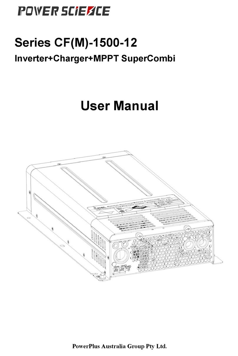
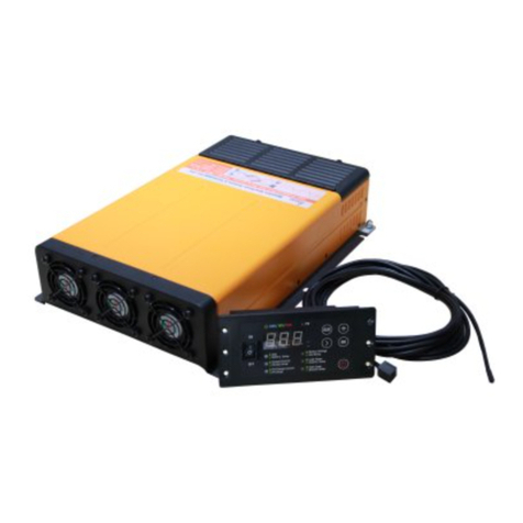
Power Science CF-3K-12 Series User manual

Series CF(M)-3K-12
Inverter+Charger SuperCombi
Australian Version
Users’GUIDE (Ver. 4.2.1)
Power Science Australia Group Pty Ltd
Jan. 2020

CF-3K-12 SUPERCOMBI USER’S GUIDE
1
Table of Content
1. Safety Instructions........................................................ 3
1.1 General Safety Warnings.....................................................................................................3
1.2 Attentions to the Batteries...................................................................................................3
2. Product Introduction....................................................... 3
2.1 Basic Introduction...............................................................................................................3
2.2 Model Definition.................................................................................................................4
2.3 Application Areas................................................................................................................5
2.4 Dimension and Mounting Holes Chart................................................................................6
2.5 Introduction to the Interfaces of Device..............................................................................6
2.6 Introduction of the Installation Cabin and the Interface definition.....................................7
2.7 Display/Settings Panel Introduction....................................................................................8
2.8 Basic Features.....................................................................................................................9
3. Installation instructions................................................. 10
3.1 Installation environment....................................................................................................10
3.2 System connection diagram..............................................................................................11
3.3 Cabling..............................................................................................................................12
3.4 Match the Battery and the Charge Current........................................................................12
4. Basic Settings............................................................ 13
4.1 Battery Type......................................................................................................................13
4.2 Charge Current..................................................................................................................14
4.3 Grid Limit .........................................................................................................................14
4.4 Auto Invert ........................................................................................................................15
4.5 Floating Charge.................................................................................................................15
5. User’s Guide .............................................................. 15
5.1 Invert.................................................................................................................................15
5.2 Energy Save Mode............................................................................................................16
5.3 AC Charge.........................................................................................................................16
5.4 PV Charge (Optional)........................................................................................................16
5.5 Auto Sleep.........................................................................................................................17
5.6 Turn off the Panel Manually..............................................................................................17
5.7 Emergency Mode..............................................................................................................17
6. Functions................................................................. 18
6.1 Dual AC Outputs...............................................................................................................18
6.2 ChargePro Function(Optional)..........................................................................................18
6.3 Load Priority.....................................................................................................................19
6.4 On-Grid Supply.................................................................................................................19
6.5 Power Support...................................................................................................................19
6.6 Wire Compensation to the Battery Voltage (Optional)......................................................19

CF-3K-12 SUPERCOMBI USER’S GUIDE
2
6.7 Charge the Start Battery (Optional) ..................................................................................19
7. Special Functions......................................................... 20
7.1 Battery Type Customization..............................................................................................20
7.2 Temperature Compensation to the Battery Voltage...........................................................20
7.3 Dead Battery Charging......................................................................................................20
8 Electrical Parameters...................................................... 20
9. Trouble Shooting.......................................................... 22
10. Warranty................................................................. 23

CF-3K-12 SUPERCOMBI USER’S GUIDE
3
1. Safety Instructions
1.1 General Safety Warnings
In order to avoid the malfunction and danger, please do not expose the machine to the
environment such as rain, clouds, mist, dust, high temperature and so on or place it in the
bilge. (For more details, please refer to the 4-2 section of the second chapter “installment
advice”)
Stay away from the fire and welding places. Use good electric conductivity wire with
appropriate length and wire diameter. (For more details, please refer to the wire available
instructions of 3.3) Devices would be damaged and its performance would be reduced if the
wire does not meet the requirement.)
Product contains internal components, which may bring electric arc and sparks. In order to
prevent fire or explosion, it is not allowed to install the machine in the narrow space with
battery or inflammable material. ( including machines powered by gasoline in any space, fuel
tanks or pipe fitting and other components)
1.2 Attentions to the Batteries
When the chemicals inside of the batteries touch the skin or clothing, please wash
immediately with plenty of soapy water.
No smoking or sparks or ignition engine near the batteries.
When using the metal tools, please be care and do not drop it on the batteries. The dropped
metal tools may cause sparks or short circuit and the explosion of battery.
When installing the batteries, please remove metal objects such as rings, bracelets, necklaces,
watches, and so on. The current generated by the short circuit of the battery is very large, and
it is possible to weld and burn the metal, which can cause severe burns.
2. Product Introduction
2.1 Basic Introduction
“The series CF(M)-3K-12 Charging-Inverter-MPPT SuperCombi” (hereinafter referred to as
“SuperCombi”) is independently developed by Power Science Technology Co., LTD.. The power

CF-3K-12 SUPERCOMBI USER’S GUIDE
4
electronic transformation device with high power density, super large charging current is
integrated with charging, inverted and photovoltaic MPPT controller, and is achieved by the
patented bidirectional convert technology:
As a charger, the machine can output an up to 200Ampere charging current;
As an inverter, the pure sine wave is output, which is very fit for the sensitive and motor
loads;
As an MPPT controller, the module is so small that it can be installed inside the machine.All
the resources, including the cable, the screen, the cooling system can be shared;
The Inverter Enhanced Functions of the SuperCombi can dramatically improve the adaptable
ability to large loads; The ChargePro Function of the SuperCombi can make full use of theAC
power from the utility and protect the battery; Hierarchical management and strong and perfect set
up function can be suitable for all kinds of users’ habits, and provide great convenience for users.
The SuperCombi is applicable to vehicle, marines and Energy Storage System etc.
2.2 Model Definition
The model format of the series products is defined as follow:
CF M -3K-12-200A - D -100 -A C N C G P R T B Y -001
* a b # ②③④⑤⑥⑦⑧⑨⑩(11) (12) (13)
Table 1: ModelDefinition
No.
Spec.
Values
*
Solar Panel MPPT Module
M: With MPPT module
Empty: Without MPPT module
a
Invert Power
2K: 2000W; 3K: 3000W
b
Max. Charge Current
200: 200A/150: 150A/100: 100A
135: 135A/100: 100A/60: 60A
0: 0A(Only Inverter, not Combi)
#
AC Outputs
D: Double Outputs. Find more in 6.1 Dual AC Outputs.
Empty: Single Output
②
Actual Max. Charge Current
If a=2K Then Empty
If a=3K Then
100: 100 Amperes
150: 150 Amperes
Empty: 200 Amperes
③
Country Code
A: Australia
④
Invert AC Voltage
A: 220Vac / B: 230Vac / C: 240Vac
⑤
Charge function
Empty: With Charge Function
N: Without Charge Function
⑥
ChargePro Function
C: With ChargePro Function. Find more in 6.2 ChargePro
Function (Optional)

CF-3K-12 SUPERCOMBI USER’S GUIDE
5
Empty: Without ChargePro Function
⑦
Invert Enhanced Function
G: With On-Grid Supply Function. Find more in 6.4
On-Grid Supply.
S: With Power Support Function. Find more in 6.5 Power
Support.
Empty: Without any Invert Enhanced Function
⑧
Work in Parallel
P: The SuperCombis can work in Parallel
Empty: Without Work in Parallel Function
⑨
Wire Compensation
R: With Wire Compensation Function. Find more in 6.6
Wire Compensation to the Battery Voltage (Optional)
Empty: Without Wire Compensation Function
⑩
Temperature Compensation
T: With Temperature Compensation Function. Find more
in Temperature Compensation to the Battery Voltage.
Empty: Without Temperature Compensation Function
(11)
To Charge the Start Battery
B: With the function of Charging the Start Battery. Find
more in 6.7 Charge the Start Battery (Optional)
Empty: Without the function of Charging the Start Battery
(12)
Color
Empty: Green
Y: Orange
(13)
Customer Number
3 Digitals: Customized for the special customer
Empty: Standard Product
2.3 Application Areas
Electric Tools: round saws, electric drills, grinder, buffers, weeding machine, air
compressors.
Office equipment: computer, printer, display, fax machine, scanner
Household products: Fixed frequency, inverter air conditioner, hair dryer, vacuum cleaner,
fan, fluorescent lamp, incandescent lamp, electric razor, electric sewing machine.
KitchenAppliance: Coffee maker, mixer, ice maker, toaster.
Industrial equipment:Metal halide lamp, high pressure sodium lamp.
Home entertainment electronic goods: TV, recorder, video games, audio, musical instruments,
satellite equipment.

CF-3K-12 SUPERCOMBI USER’S GUIDE
6
2.4 Dimension and Mounting Holes Chart
The maximum size of the SuperCombi is 386*262*83.1, and there are six symmetrical mounting
holes on both sides with a diameter of 5.5mm. The specific dimensions charts are shown as in
Figure 1.
Fig.1. Dimension and Mounting Holes Chart
2.5 Introduction to the Interfaces of Device
User’s installation chart shown as Figure 2:

CF-3K-12 SUPERCOMBI USER’S GUIDE
7
Figure 2 SuperCombi installation surface Chart
Each part is defined as shown in table 2:
No.
Function definition
①
PV Input
②
AC IN/OUT
③
Indicator
④
Black, Sampling of Battery (Optional)
⑤
White, Remote Control
⑥
Charge Port (2A) for Start Battery (Optional)
⑦
Emergency Swith
⑧
Battery
Table 2 All-in-One machine mounting surface definition table
2.6 Introduction of the Installation Cabin and the Interface
definition
The diagram of the installation cabin is shown as Figure 3.
Figure 3: Diagram of the Installation Cabin

CF-3K-12 SUPERCOMBI USER’S GUIDE
8
2.7 Display/Settings Panel Introduction
Display / settings panel are shown in Figure 4 and 5:
Figure 4: Panel Diagram (Front)
Figure 4: Panel Diagram (Back)
In which:
(1) Menu
(10) Dial Switch for Auto Invert/Floating Charge

CF-3K-12 SUPERCOMBI USER’S GUIDE
9
(2) Parameter Unit
(11) PageDown/ Buzzer sound off
(3) PV Indicator
(12) Power On/Off
(4) Working Indicator
(13) Buzzer
(5) Parameter Value
(14) Remote
(6) Rocker Switch (On/Off/Energy Save)
(15) Reserved
(7) Battery Type Selector
(16) Reserved
(8) AC (Grid) Current Selector
(17) QR Code (For Help)
(9) Charge Current Selector
Table 3 Panel definition table
2.8 Basic Features
Pure Sine Wave Output
High Efficiency: The efficiency can be up to 93%
X-small size
Large Charge Current: The Max. Current can be as high as 200A
Surge power can be three times of continuous output
Wide DC Input range: Full Power Output @ battery voltage 10~15V dc, De-rated Power
output @ battery voltage 9~10Vdc
The built-in 32AAC Relay can achieve larger bypass power.
Energy Saving Mode: Ultra-low Loss, standby power consumption can be lower than 10W.

CF-3K-12 SUPERCOMBI USER’S GUIDE
10
3. Installation instructions
Note: Before installing, make sure that the Emergency Manual Switch (Figure 8) of the
SuperCombi is OFF. Otherwise, you will face the risk of battery damage! Excpet the "emergency
mode", this switch must be kept OFF at other times.
Figure 5: Emergency Manual Switch
Fig. 6 Super-Combi Installation Space Diagram
3.1 Installation environment
Installation site of All-in-One machine must comply with following rules and requirements:
(1) Dry: It is not allowed to place the product in the place with water and humid.
(2) Temperature: The suitable working temperature is between -20℃~+50℃.
(3) Safety: Do not place it near by the fire, inflammable, fuel, generator equipment.
(4) Ventilation: There shall be at least 30cm ventilation space without obstruction in the head and
rear, so that the heat inside the product can be released. Shown as the Figure 6.
(5) Dust Proof: Do not install it in the place surround by dust, grind, or cutting. The dust will be
sucked into the machine, and cause the malfunction of the machine.
(6) Anti-Corrosion Gas:Avoid exposing to the environment with corrosion gas for a long time.

CF-3K-12 SUPERCOMBI USER’S GUIDE
11
3.2 System connection diagram
Fig. 7 System Connection Diagram
Note: Find more details about the DualAC Outputs.in 6.1

CF-3K-12 SUPERCOMBI USER’S GUIDE
12
3.3 Cabling
No.
Cabling Position
Recommend Cable Specification
1
AC IN
Copper Cable with the cross sectional area
larger than 6mm2
2
AC OUT1: Power
Copper Cable with the cross sectional area
larger than 6mm2
3
AC OUT2: Short Break
Copper Cable with the cross sectional area
larger than 6mm2
4
Battery
Copper Cable with the cross sectional area
larger than 75mm2
(
note
)
5
PV
Copper Cable with the cross sectional area
larger than 4mm2
Table 4 Cabling Instructions Table
Note
:
The length of the cable from the battery terminals to the All-in-One machine should be as
short as possible. Less than 1 meter is preferred.
Warning: The consequences caused by the improper installation are
not borne by our company!
Before connecting the battery, please double check the input polarity to the battery is
connected correctly. Wrong polarity connection will damage the appliances;
For safety, the grid should be cut off before or during the installation;
To avoid short circuit of the battery during the installation, the battery should be protected
and inaccessible to other appliances;
The torque of the cable should be strictly limited according to the requirements of Table 18.
Excessive torque will causes the damage of the bolt and even cause other potential dangers
such as short circuit or fire etc.;
It’s very normal that there might be spark during the first connection with the battery;
3.4 Match the Battery and the Charge Current
For charging safety, the "maximum charging current" of the SuperCombi should match the charge
current recommended by the battery factory to avoid the risk of damage to the battery due to the
mismatch of charging current

CF-3K-12 SUPERCOMBI USER’S GUIDE
13
Note that if any accidental loss caused by the mismatch of charging current, battery damage or
various losses caused by fire and explosion, is not within our responsibility!
4. Basic Settings
Note: Before setting, make sure that the Rocker Switch should be in the middle gear as shown in
the following figure. Otherwise, it will damage the battery.
Figure 8: Turn off the Rocker Switch
Figure 9: Battery Type Selector
4.1 Battery Type
According to the type of battery installed, the customer can adjust the corresponding battery
position by turning the “Battery Type” Selector (see Figure 9) according to the battery information
in the following table.
No.
Battery Type
Dead Battery
Max Voltage
CV
Voltage
Floating
Voltage
LBCO
1
GEL
9V
/
14.1V
13.7V
10.2V
2
AGM 1
9V
/
13.8V
13.4V
10.2V
3
AGM 2
9V
/
14.3V
13.7V
10.2V
4
Flooded
9V
/
14.8V
13.3V
10.2V
5
Lithium Iron
9V
10V
14.5V
13.5V
10V
6
Lithium
Ternary
7.2V
9V
12.6V
11.7V
9V
Table 5:Battery Type

CF-3K-12 SUPERCOMBI USER’S GUIDE
14
4.2 Charge Current
In order to meet the needs of customers in different application scenarios, the all-in-one can adjust
the battery charging current through the "charging current" selector (Figure 10). The larger the
charging current, the faster the charging speed is, and the smaller the charging current, the slower
the charging speed is.
The absolute value of "charging current" is calculated based on the "maximum charging current"
of the SuperCombi and then the percentage set by the selector. For example, the "maximum
charging current" of the SuperCombi is 200A and the Selector is set to 12.5%, the calculation
result is: 200 * 12.5% = 25A, if the "maximum charging current" of the SuperCombi is 100A, and
the selector is set to 12.5%, the calculation result is: 100 * 12.5% = 12.5A
Note:
(i) If customer has plenty of time, it is recommended to reduce the "charging current" to increase
the battery life.
(ii) If you charge the battery in a limited time, you can increase the "charging current" to charge
the battery full in a short time, but the current must be strictly in accordance with the safe charging
current provided by the battery manufacturer
Figure 10: Charge Current
Selector
Figure 11: Grid Limit
Figure 12: Auto Invert/Floating
Charge
4.3 Grid Limit
In order to adapt to customers' different power usage occasions, customers can use the “mains
maximum current” knob (see Figure 11) to set the max. current which the SuperCombi can get
from the grid. According to the value, the SuperCombi can make full use of the power from the
grid and also can prevent the grid be overloaded. This parameter is mainly used for "load priority"
and optional "separate power supply" and "grid supply" functions.
Note: The value of the Grid Current Limit should not be larger than the value of the Mains Circuit
Breaker, otherwise the breaker would be protected.

CF-3K-12 SUPERCOMBI USER’S GUIDE
15
Figure 11: Grid Limit
Figure 12: Auto Invert/Floating Charge
4.4 Auto Invert
The user can enable or disable Auto Invert function by different setting of the dial switch (See
Figure 12).
1. When enable the Auto Invert function, the SuperCombi will output AC power automatically
when the SuperCombi disconnect with the Grid;
2. When disable the Auto Invert function, the SuperCombi will not output AC power when the
SuperCombi disconnect with the Grid and enter to Standby state;
4.5 Floating Charge
When battery fully charged, the user can enable or disable the Floating Charge function by
different setting of the dial switch (See Figure 12).
1. When enable the Floating Charge function, the SuperCombi will still charge the battery at very
small current to compensate the self-discharging current;
2. When disable the Auto Invert function, the SuperCombi will stop working till the battery
voltage is only 1 volt higher than the cut off Voltage.
5. User’s Guide
5.1 Invert
When disconnect with the Grid, the SuperCombi will have two working statuses according to
different Auto Invert settings:
1. When enable Auto Invert function, the SuperCombi will output AC power to Short Break socket
unless the Rocker Switch stays on the middle. The indicator will turn green;
2. When disable Auto Invert function, the SuperCombi will enter into Standby mode. The indicator
will turn Red.
Note: Please find more information about the Energy Save mode in 5.2

CF-3K-12 SUPERCOMBI USER’S GUIDE
16
5.2 Energy Save Mode
To reduce the loss when the SuperCombi work without load, the user can choose Energy Save
Mode by putting the Rocker Switch to the second gear. Under the Energy Save Mode, if the AC
load of the system is less than 30W in 10 minutes, the SuperCombi will enter into Standby status
to reduce the loss. After 5 minutes, the SuperCombi will enter into Sleep status to further reduce
the loss.
Figure 13: Energy Save Mode
5.3 AC Charge
When connect with the Grid, the SuperCombi will work as a charger unless the Rocker Switch is
off. The grid will provide AC power to the AC output1/2 and also charge the battery. The indicator
will turn blue at this time.
When charging, if the customer presses the power button for 3 seconds, the SuperCombi will stop
charging. The SuperCombi will continue to provide AC power to AC Output1/2. The indicator will
turn flashing blue.
Again, if the customer presses power button for 3 seconds, the SuperCombi will enter into charge
mode.
If the Charge Pro function added, more features can be expected. For details about Charge Pro
function, to see 6.5.
Note: When charging, there is no difference between Power ON and Energy Save.
5.4 PV Charge (Optional)
The solar panel will charge the battery automatically unless the SuperCombi is power off. Under

CF-3K-12 SUPERCOMBI USER’S GUIDE
17
PV charging mode, the PV indicator will turn flashing green. There are 3 working statuses as
follow:
(1) Under inverting condition: The solar and the battery will provide DC power together for
inverting, but the solar power will have the priority to provide up to 500W energy for
inverting.
(2) Under AC Charging condition: The solar and the Grid will provide energy for charging. As
inverting, the solar has the priority to provide up to 500W energy for inverting.
(3) Under the Standby & Sleep mode: The solar will charge the battery directly.
5.5 Auto Sleep
To further reduce the loss, the panel will enter into sleep mode automatically when the standby
mode last for 5 minutes. All the light of the digital cube and LED will turn off. The panel can be
woken up by pressing any button.
5.6 Turn off the Panel Manually
To avoid disturbing the customers because of the light from the panel, the panel can be turned off
manually.
Pressing the PgDown button for 2 seconds, the customer can turn off all the light.
Figure 14: Turn ON/OFF the Panel manually
To turn on the panel, pressing the PgDown button as shown in Figure 14.
5.7 Emergency Mode
In order to minimize the impact on the customer when a failure occurs, the SuperCombi can run
normally when the control panel encounters an unexpected accident, such as: when the system

CF-3K-12 SUPERCOMBI USER’S GUIDE
18
suddenly encounters the control panel during normal operation When the all-in-one cannot be
operated normally due to damage or loss of connection, at this time, you can unplug the control
panel cable at the end of the all-in-one and turn on the emergency manual switch. The all-in-one
will restart operation and its original 6 parameter status will remain unchanged ( Energy saving
mode, charging current, mains maximum current, battery type, floating charge, automatic inverter).
After the all-in-one runs normally, please contact the manufacturer to repair the control panel or
cable as soon as possible.
6. Functions
6.1 Dual AC Outputs
The SuperCombi provides dual AC Outputs, Power and Short Break. Different AC loads can be
connected to different ports. The heavy AC loads can be connected with the Power port, and the
lightAC Loads can be connected with the Short Break port.
Power Port: This port is directly connected with the AC input. When SuperCombi is connected
with the grid, the Power Port can provide the AC power to the load from the grid. When
SuperCombi is disconnected with the grid, the Power Port can’t provide theAC power to the load.
Short Break Port: This port is connected with the AC input via the build-in relay. When
SuperCombi is connected with the grid, the relay will be on. This port is connected with both the
grid and the inverter output. The Short Break Port can provide the AC power to the load from the
grid and the inverter. When SuperCombi is disconnected with the grid, the Short Break Port can
still provide the AC power to the load from the inverter.
Figure 15: DualAC Outputs
6.2 ChargePro Function(Optional)
The SuperCombi can provide DC Power to both the load and the battery. The DC output current of
the SuperCombi can be adjusted according to different load while keeping a constant charging

CF-3K-12 SUPERCOMBI USER’S GUIDE
19
current. Under this function, the 200Amperes of the SuperCombi is very useful.
6.3 Load Priority
When the utility is limited, the AC loads have the priority to get the power and then the rest of
power will be converted to DC to the battery or the DC load.
6.4 On-Grid Supply
When connected with the utility, the SuperCombi can work together with the utility to provide
another 3kW power to theAC load.
Figure 16: On-Grid Supply Diagram
Figure 17: Power Support Diagram
6.5 Power Support
When connected with the utility, the SuperCombi can work together with the utility to provide
another 3kW power to the AC load.
6.6 Wire Compensation to the Battery Voltage (Optional)
Line loss will have significant impact under the low voltage and high current circumstance. To
charge or discharge the battery more accurately, the voltage on the SuperCombi DC ports should
be modified..
By using the Line Loss Compensation function, the SuperCombi will get more accurate Voltage of
the battery.
6.7 Charge the Start Battery (Optional)
The SuperCombi also provides a 2Ampere port to charge the start battery.
Other manuals for CF-3K-12 Series
1
This manual suits for next models
1
Table of contents
Other Power Science Inverter manuals
Popular Inverter manuals by other brands

AIMS Power
AIMS Power PWRI150012120S instruction manual

Growatt
Growatt SPF 3500TL LVM-US user manual

Mastervolt
Mastervolt WHISPER 9 user manual

Campbell Hausfeld
Campbell Hausfeld IN198203AV operating instructions

Mitsubishi Electric
Mitsubishi Electric FR-E5NC instruction manual

Fimer
Fimer MEGASTATION Installation, operation and maintenance manual