RedEarth HoneyBadger User manual

HoneyBadger_InstallationManual
RE_PROD_0009 Version #1 Page 1 of 20 Issue Date 28/07/2020
HoneyBadger
Home Battery System – Off-Grid
Victron + Lithium Batteries
Installation Manual

HoneyBadger_InstallationManual
RE_PROD_0009 Version #1 Page 3 of 20 Issue Date 28/07/2020
WARNING: Working on the inside of the HoneyBadger system is restricted to qualified personnel.
In Australia this is typically qualified electricians with CEC accreditation for Solar and Battery.
WARNING: Lithium Battery hazard
The HoneyBadger must only be installed by suitably qualified personnel who have
read and are familiar with its operation and hazards.
Many of the procedures covered in the INSTALLATION sections of this manual have
inherent risks. Whilst the HoneyBadger is designed to be safe, including residual
current device and double insulated cables, the voltages connected or generated
by the equipment are hazardous and potentially fatal.
Safety
CAUTION: The battery provided with this system must be charged only by the
Victron inverter provided as it is properly configured. Do not attempt to charge the
batteries with any other charger device or connect any devices directly to the DC
battery bus.
The wiring diagrams and installation instructions are given as a guide only and
compliance to appropriate standards is the responsibility of the installer. Such
standards are listed below:
AS/NZS 3000:2018
Wiring rules
AS/NZS 5033:2014 (amdt 1&2)
Installation and safety requirements for
photovoltaic (PV) arrays
AS/NZS 4509.2:2012
Stand-alone power systems-Design
AS/NZS 1170.2:2011
Structural design actions-Wind actions
AS/NZS 4777.1:2016
Grid connection of energy systems via
inverters-Installation requirements
AS/NZS1768:2007
Lightning protection
AS/NZS 3008.1.1:2017
Electrical installations – Selection of cables
AS/NZS 5139:2019
Electrical installations-Safety of battery
systems for use with power conversion
equipment
In our efforts towards constant product enhancement, this document is subject to
change at any time. Please visit www.redearth.energy
and download the
appropriate and latest version manual.

HoneyBadger_InstallationManual
RE_PROD_0009 Version #1 Page 4 of 20 Issue Date 28/07/2020
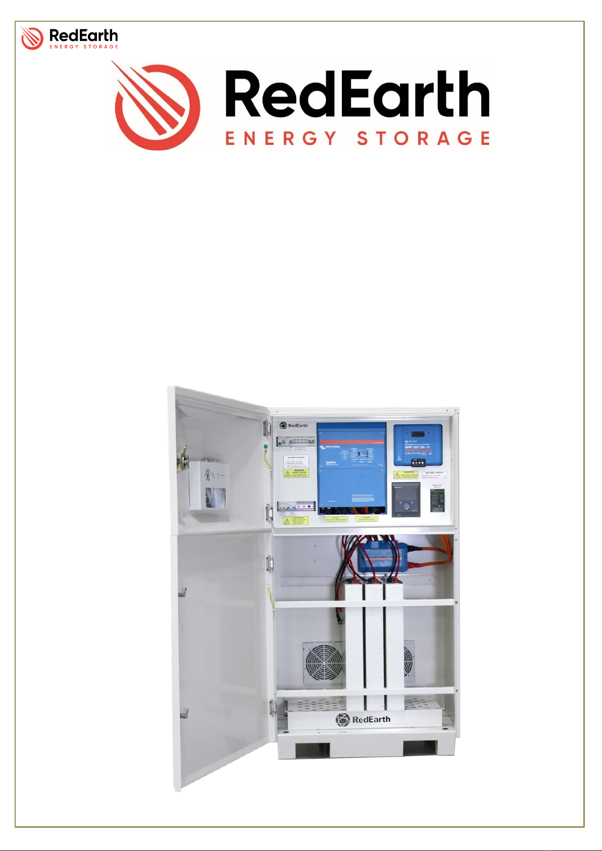
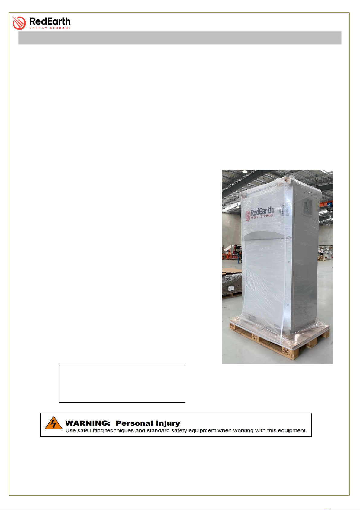
RedEarth’s HoneyBadger battery system is a ready-to-run energy storage system for off-grid
applications. It includes a 5 or 10kVA Victron Quattro inverter, one(1) or two(2) Maximum Power
Point Tracker (MPPT) and self-managed lithium batteries. It is fully aHBembled, factory tested and
requires no programming*.
It is ready to connect a PV Solar array (maximum 5 panels in series (250Vdc) and and generator
(either auto or manual start)
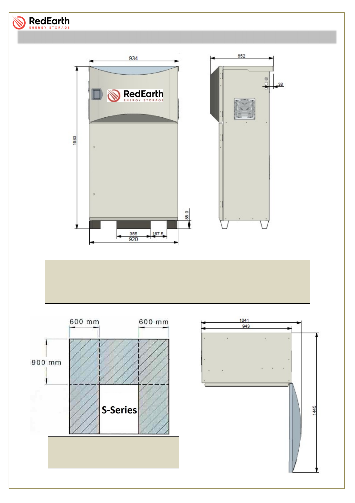
The HoneyBadger system is designed to be installed either inside or outside, ideally in a shaded
area against a wall. A changeover switch is included in case of system failure. In this case the loads
can then be run off a generator until the system is operational again.
The HoneyBadger can be remotely monitored and managed online using Victron’s VRM App or
VRM Website. RedEarth Energy Storage can also provide a remote monitoring service to ensure
ongoing operation of the HoneyBadger battery system.
A typical complete installation of the HoneyBadger with Victron inverter and Victron MPPT, will
require the electrical connection of:
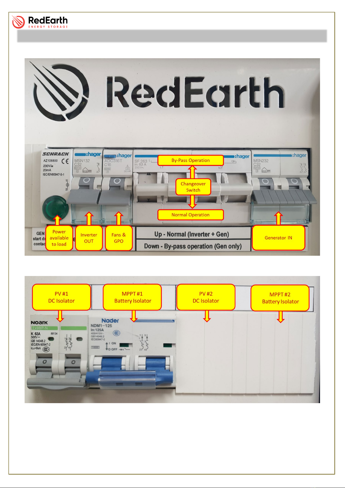
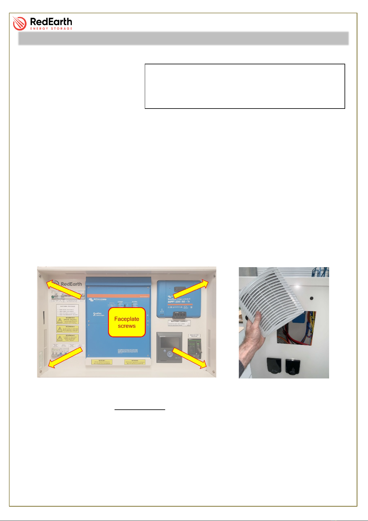
The customers load – there are dedicated terminals inside the unit to connect to.
One array of PV solar panels (maximum 250VDC per string) (If two MPPTs are included in your
system then two arrays can be installed, with different orientations.).
Generator, if available (2-wire auto start or manual start generator). Terminals for connecting a dry-
contact compatible generator start or signal light are included.
In addition, the installer may need to program the Victron CCGX controller for the customer’s specific
requirements (e.g. generator run times) and connect the internet using one of the available options;
aHBuming remote monitoring is requested. The most reliable is a direct connection from the
customers router into the rear of the CCGX display. RedEarth can provide an optional SIM-card
based monitoring solution if the customer does not have internet and the installation site has mobile
coverage.
Note: The
HoneyBadger is not
designed to act as a
main switch board for
the premises, as it
does not include
space for additional
main & customer
circuit breakers or
RCDs. The MEN link
and Earth connection
need to be in place at
the premises as
required.
Overview:
*If all details are provided upon purchase

HoneyBadger_InstallationManual
RE_PROD_0009 Version #1 Page 5 of 20 Issue Date 28/07/2020
HoneyBadger Weight: 392kg with 4x Lithium batteries (42kg per battery)
Dimensions w/ door closed: 169 H x 94 W x 65 D [cm]
Dimensions w/ door open: 169 H x 104 W x 144 D [cm]
Physical Specifications
HoneyBadger Minimum Clearance
According to AS/NZS 5139

HoneyBadger_InstallationManual
RE_PROD_0009 Version #1 Page 6 of 20 Issue Date 28/07/2020
Inside
The HoneyBadger has two areas, one for the batteries and the other for the switches and electronic
equipment. Each section has a key-lockable double door.
The top enclosure contains all of the electric-electronic equipment, switches and AC connection
terminals.
Behind the face plate, you will come across the following devices.
Components

HoneyBadger_InstallationManual
RE_PROD_0009 Version #1 Page 7 of 20 Issue Date 28/07/2020
Amongst the AC Breakers you will find several AC protective, isolation and the changeover switch.
Each device contains an identification labelled directly above it. Identification can also be seen in
the picture below.
Directly below are the DC Breakers responsible for isolating the PV array and the MPPT.
Components

HoneyBadger_InstallationManual
RE_PROD_0009 Version #1 Page 8 of 20 Issue Date 28/07/2020
The bottom enclosure consists of a robust and perforated base to support full weight of the batteries
and a front and rear rail to secure the batteries in place.
Attached to the top of this chamber there are two fully enclosed battery busbars with the correct
amount of battery connecting cables.
The HoneyBadger comes fully equipped with the following items.
•HoneyBadger pre-wired enclosure
•Victrion Quattro inverter
•Victron MPPT
•Parts Kit Box
o4x: Timber M6 screws
o4x: Dynobolt M10
o1x: PV and Battery Sticker Kit
o3x: Glands
o3x: Plain-to-screw adapters
•Installation Manual
•User Manual
•Victron manual
•Battery Specifications
Components

HoneyBadger_InstallationManual
RE_PROD_0009 Version #1 Page 9 of 20 Issue Date 28/07/2020
Steps to complete your HoneyBadger installation:
1. Transporting
2. Securing in position
3. Electrical connections
4. Online monitoring and Communications
5. Finalizing
1. Transporting
The HoneyBadger system is supplied on a pallet as shown at right. It is fully set-up and ready to
run. The system weighs around 392kg with 4x lithium batteries and requires lifting equipment to
handle it. The system can only be lifted from the base.
The base of the system has spaces for either a forklift or a
standard trolley jack to be used.
If the HoneyBadger is too heavy to manage the lithium
batteries can be removed and replaced once the system is in
position. Each battery module weighs 42kg and up to eight (8)
can be installed in the system.
The HoneyBadger is designed to be a freestanding
weatherproof system. However, we strongly recommend it to
be placed against a wall in a shaded area. The top of the unit
has fixing points to attach the unit to the wall to ensure that it
cannot tip over.
Cable entry options are available on both sides of the system.
They are designed for 25mm conduit, and 3 glands are
provided in the spares which clamp onto 25mm flexible
conduit.
Air inlet vents are included in the base and sides of the
system. Do not block them.
Installation
Face Plate that covers the cabling
comes strapped to the side of the
unit to avoid transport damage

HoneyBadger_InstallationManual
RE_PROD_0009 Version #1 Page 10 of 20 Issue Date 28/07/2020
2. Securing in position
With the help of a forklift of a trolly-
jack, roll the system into place and
secure it to the wall as well as the
floor.
Securing the system to the wall is done by screwing through the hole on the left and right corner of
the systems roof. The HoneyBadger also has four holes in the base to allow for securing. This can
be done with dynabolts or material appropriate screws.
Masking tape may be applied to the unit. This is strategically positioned in common rubbing spots
and the purpose of the tape is to avoid paint chipping during transportation. This can now be
removed.
3. Electrical connections
To access the cable connection points, remove the faceplate by undoing the 4 screws holding it in
place. This allows access into the unit to pull through cables, as well as connect the internet cable
to the back of the CCGX monitor. It is also possible to remove the vent on the side of the unit. This
gives better access if required. The vent is removed by pressing the locking tabs from the inside of
the unit and pulling the vent off. (see image at right)
NOTE: Before proceeding any further, ensure that all breakers and isolators, as well as those
supplying power to the unit, are turned OFF.
DC Connections
Battery
The batteries are located in the lower enclosure, behind the bottom door.
If supplied separately, unbox the batteries, remove the front battery rail, place batteries the battery
shelf, re-install the front battery rail and finally attach the battery cables.
Installation
IMPORTANT: Before positioning the HoneyBadger
, be
sure that there is an available area of 1690 x 1040 x 1445
(H x W x D). This will allow a minimum of 90⁰ open door
angle as well as lateral ventilation.

HoneyBadger_InstallationManual
RE_PROD_0009 Version #1 Page 11 of 20 Issue Date 28/07/2020
PV Connections
Amongst the DC breakers, you will find a tab that identifies
where the PV cables must be connected. If the tab has come
lose, connect the cables to the top side of the “NOARK – 63A”
MCB. The picture aside shows the setup of only one MPPT.
Note that the PV array must always be wired in a way that keeps
the voltage below 250Vdc.
NOTE: Ensure that the polarity of the array is correct.
AC Connections
AC cables should be inserted through the side panel, secured appropriately with a 25mm gland
provided (or plain-to-screw if using corrugated conduit), and attached to the correct terminals of the
breaker as shown below.
Load
The active cable must be connected to the bottom side of the unit’s main breaker. This MCB can be
identified as the far-left breaker on the AC side or by the “LOAD” tab. Neutral and Earth cables must
be connected to their respective busbars.
NOTE: The LOAD connection should come from a
Main Switch Board which contains the MEN link and
Earthing required for the premises.
NOTE: Caution whilst installing this cable as there is
another smaller cable also attached. Be sure that
when finished, both cables are firmly attached.
Generator termination
Active and neutral must terminate into the bottom side of the generator breaker. This MCB can be
identified as the far-right breaker on the AC side or by the “GENERATOR” tab. Earth must be
screwed into an empty slot in the Earth Bar.
NOTE: The MCB is rated at 50A, be sure to use appropriate cabling.
Generator Auto-Start and Charger
HoneyBadger contains two terminals on the left end of the top DIN rail that do not appear when the
faceplate is installed. These terminals are connected to a dry contact that can be programmed to
automatically start a generator, or it can be used to activate a signal light indicating that the manual
start generator is required.
Installation

HoneyBadger_InstallationManual
RE_PROD_0009 Version #1 Page 12 of 20 Issue Date 28/07/2020
4. Online Monitoring and Communication
The Internet must be plugged into the rear of the CCGX if on-line monitoring is desired. (see image
of rear of CCGX below) As an alternative a WiFi antenna can be plugged in and synced with a local
wifi (does not come as standard). A third and strongly recommended by RedEarth is to connect a
SwitchDin Droplet. This can provide 4G internet access to the system and detailed troubleshooting.
If monitoring is provided and the customer wishes to monitor their system via the VRM APP or on
their PC, then the customer will need to provide an email address to RedEarth. They will then receive
login details emailed to them. This email address can be provided prior to installation.
NOTE: the installer can also receive this same access if they provide an email address, otherwise
all monitoring is only available via the CCGX, when standing in front of the HoneyBadger unit.
Installation

HoneyBadger_InstallationManual
RE_PROD_0009 Version #1 Page 13 of 20 Issue Date 28/07/2020
4.1. Installing SwitchDin
To install the SwitchDin device, unplug the antenna from the droplet, pass the same plug through
the hole identified with the “EXTERNAL ANTENNA” sticker, re-plug the antenna in the same port
and then tighten the gland onto the unit. Once this is done, place the antenna in a open area
with good cellular reception.
5. Finalizing
Before attaching the faceplate, go through the following items and be sure that they have been
attended.
1. Once the wiring described above is completed insert the supplied blanking plugs into the
unused holes in the side of the unit.
2. AC cables are connected to the correct terminals with regards to load and supply
(Grid/Generator).
3. The system is correctly earthed, either via the customer’s local earth or through a locally
installed earth stake. A MEN link is installed as required.
4. The PV cables are tightly connected via an external PV combiner box (if required) for each
MPPT, and the polarity is correct.
5. The battery terminal connections are tight. (check after transportation)
6. Insert the supplied blanking plugs into the unused holes in the side of the unit and secure the
lateral vents.
7. Attend to any last-minute commissioning details (See Commissioning in this manual).
8. The system is now ready for Start-up.
Installation

HoneyBadger_InstallationManual
RE_PROD_0009 Version #1 Page 14 of 20 Issue Date 28/07/2020
The HoneyBadger is commissioned and tested in factory to guarantee correct operation. However,
last-minute parameter adjustments may be required (eg. generator size or increasing energy
storage). Carefully follow the procedure below on how to make these alterations without
compromising the existing configuration.
NOTE: This must be done by a qualified person.
NOTE: To do these changes, you will need a MK3 device and the VE Config program. The MK3
device does not come with the HoneyBadger as a standard tool. However, it may be purchased if
required. The VE Config program can be downloaded for free Victron’s web page
(https://www.victronenergy.com.au/)
The complete system is pre-wired, and factory tested. The original Victron Quattro inverter and
battery manuals are included in the pocket in the door of the system, along with the inverter
configuration sheet. These may need to be referred to for additional details required during setup
and programming.
All parameters that are configured by using
the MK3 device are printed in a sheet and
available with the rest of the HoneyBadger
documentation behind the door. To change
parameters using the MK3, please refer to the
VEConfigure Manual available on Victron’s
web page.
Parameters that are not available in VE
Config, can be found by accessing the Color
Control GX (CCGX). The CCGX display has several pages for monitoring and setting parameters.
Refer to https://www.victronenergy.com/live/ccgx:startor the included Manual for details.
Complete programming of the CCGX according to the customers’ requirements.
The thermostat is located at the rear of unit next to the left fan.
This automatically starts the fans once the temperature rises
above the set-point. This set-point can easily be adjusted with a
small screwdriver. It is set to 35⁰ Celcius in the factory.
Commissioning

HoneyBadger_InstallationManual
RE_PROD_0009 Version #1 Page 15 of 20 Issue Date 28/07/2020
Once the HoneyBadger is in place and correctly installed, you may start the system.
To power up the unit you must follow the steps below:
1 Switch on the battery breakers on the top of each lithium battery. The LED light on each
battery will come on.
2 Switch on the Main Battery Isolator; the Quattro Inverter and CCGX display will start (note
the small black switch on the front of the Inverter itself needs to be in the ON position)
3 Switch on the MPPT #1 and #2 Isolator
4 Switch on the PV Array #1 and #2 Isolator
5 Position the Changeover switch upwards (position 1);
6 Turn ON all AC circuit breakers
The shutdown procedure is shown below. This label is affixed to the inside of the HoneyBadger.
Start-up / Shutdown Procedure

HoneyBadger_InstallationManual
RE_PROD_0009 Version #1 Page 16 of 20 Issue Date 28/07/2020
RedEarth is available to assist commissioning the system during business hours.
Phone Tech support on +61 487 002 451 or +61 7 3279 6707.
RedEarth also provides training in our facility in Brisbane. Training can potentially be arranged at
your facilities if requested.
Our website, www.redearth.energy includes updated documents as they become available.
Options available from RedEarth
RedEarth can provide several options for the HoneyBadger
•Additional batteries for system expansion.
•Extended warranty options.
•Miscellaneous spare parts (including indicator lights for Generator start)
•Solar kits with combiner boxes, PV panels, racking and pre-terminated PV cables
•Diesel Generator with 2-wire auto start.
•Generator backup kit (for on-grid applications)
•Ongoing remote monitoring – Concierge RED service.
RedEarth Support Options

HoneyBadger_InstallationManual
RE_PROD_0009 Version #1 Page 17 of 20 Issue Date 28/07/2020
Single Line Diagram (SLD)

HoneyBadger_InstallationManual
RE_PROD_0009 Version #1 Page 18 of 20 Issue Date 28/07/2020
Single Line Diagram (SLD)

HoneyBadger_InstallationManual
RE_PROD_0009 Version #1 Page 19 of 20 Issue Date 28/07/2020
Victron Quattro inverter/charger – Selected specifications. The HoneyBadger uses the 48/5000/70-
100/100 Quattro.
The Victron SmartSolar series of Charge Controllers are used in the HoneyBadger. The standard is
MPPT 250/100.
Technical Specifications

HoneyBadger_InstallationManual
RE_PROD_0009 Version #1 Page 20 of 20 Issue Date 28/07/2020
Specifications of the PowerPlus Energy Life4833P lithium battery module
Technical Specifications
Other manuals for HoneyBadger
4
Table of contents
Other RedEarth Inverter manuals