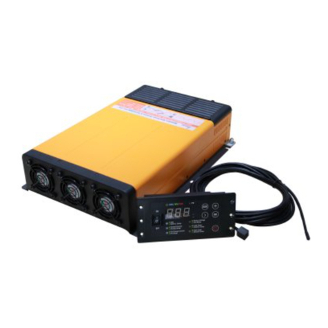
Power Science CF-1500-12 Series User manual

Series CF(M)-1500-12
Inverter+Charger+MPPT SuperCombi
User Manual
PowerPlus Australia Group Pty Ltd.

1
Safety Precautions
Please read the Safety Precautions before installing or using the SuperCombi
CF(M)-1500-12 products. Be sure to observe all precautions without fail.
Failure to observe these instructions properly may result in personal damage,
or personal injury which depending on the circumstances may be serious and
cause loss of life.
DISCLAIMER: PowerPlus Australia Group Pty Ltd accepts no liability for any loss or damage
which may occur from the improper or unsafe use of its products. Warranty is only valid if the
unit has not been modified or misused by the customer.

2
WARNINGS
1. Do not expose the machine to the environment such as rain, moisture, mist,
dust, high temperature and so on or place it in the bilge.
2. Keep away from the fire and welding processes.
3. Use good quality wire with appropriate length and wire diameter. The
SuperCombi may be damaged and its performance would be reduced if the
wire does not meet the requirement.
4. Product contains internal components, which may bring electric arc and
sparks. In order to prevent fire or explosion, it is not allowed to install the
machine in the confined space with battery or inflammable material nearby.
5. When the chemicals inside of the batteries touch the skin or clothing, please
wash immediately with plenty of soapy water.
6. No smoking ,sparks or ignition engine near the batteries.
7. When using the metal tools, please be careful and do not drop it on the
batteries. The dropped metal tools may cause sparks or short circuit and
possible explosion of batteries.
8. When installing the batteries, please remove metal ornaments such as
rings, bracelets, necklaces, watches, and so on. The current generated by the
short circuit of the battery is very large, and it is possible to weld and burn the
metal, which can cause severe burns.
9. This product is not intended for use by persons (including children) with
reduced physical, sensory or mental capabilities, or lack of experience and
knowledge, unless they have been given supervision or instructions
concerning the use of the appliance by a person responsible for their safety.
10. Batteries are always electrically live and must be treated with extreme
caution. They can supply high short circuit currents, even if they appear
damaged or undamaged.
11. Only charge battery types which are supported by this charger
12. Do not drop or shock the product, its accessories or batteries as this may
cause the product or battery to fail, catch fire or explode.
13. Ensure that the product is well ventilated, and make sure the fan is not
covered or obstructed.
14. Stay away from magnetic equipment. Radiation may erase the information
stored on this product causing it to become inoperative
15. Do NOT alter or disassemble the Battery Charger under any
circumstances. All services must be returned to PowerPlus for repair.
16. Use of an attachment not recommended or sold by PowerPlus may result
in a risk of fire, electric shock, or injury to persons

3
Contents
Safety Precautions...................................................................................................... 1
1. Product Introduction............................................................................................... 5
1.1 Basic Information.......................................................................................... 5
1.2 Model Definition............................................................................................ 6
1.3 Application Areas.......................................................................................... 8
2. Structure and Dimensions..................................................................................... 9
2.1 Dimension and Mounting Holes Chart.......................................................9
2.2 Device Interface.......................................................................................... 10
2.3 Wiring Cabin................................................................................................10
2.4 Display/Settings Panel............................................................................... 11
3. Installation Instruction.......................................................................................... 13
3.1 Installation Environment............................................................................ 13
3.2 System Wiring Diagram.............................................................................14
3.3 Cabling......................................................................................................... 15
3.4 Match the Battery and Current................................................................. 16
4. Basic Settings........................................................................................................16
4.1 Battery Type................................................................................................ 16
4.2 Charge Current........................................................................................... 17
4.3 Grid Limit......................................................................................................18
4.4 Auto Invert....................................................................................................19
4.5 Float Charge................................................................................................20
5. Operation Guide....................................................................................................20
5.1 Invert.............................................................................................................20
5.2 Energy Save Mode.....................................................................................20
5.3 AC Charge................................................................................................... 21
5.4 PV Charge................................................................................................... 21
5.5 Auto Sleep................................................................................................... 22

4
5.6 Turn Off the Panel Manually..................................................................... 22
5.7 Emergency Mode....................................................................................... 23
6. Special Functions................................................................................................. 23
6.1 Charge Pro Function..................................................................................23
6.2 Load Priority................................................................................................ 24
6.3 On-Grid Supply........................................................................................... 25
6.5 Wire Compensation....................................................................................25
6.6 Battery Capacity Testing............................................................................26
7. Extended Functions..............................................................................................26
7.1 Charger/Inverter Parameter Customization........................................... 26
7.2 Temperature Compensation......................................................................26
7.3 Dead Battery Charging.............................................................................. 27
8. Specifications........................................................................................................ 28
9. Troubleshooting.....................................................................................................30
10. Appendices.......................................................................................................... 33
11. Warranty............................................................................................................... 34

CF(M)-3K/2K-12 SUPERCOMBI USER’S GUIDE
1. Product Introduction
1.1 Basic Information
“The series CF(M)-1500-12 Charging-Inverter-MPPT All-in-One machine”
(hereinafter referred to as “SuperCombi”) is independently developed by
Power Science Technology Co., LTD.. This power electronic transformation
device featured with high power density and super large charging current is
integrated with charger, inverter and photo-voltaic MPPT controller functions. It
is achieved by the patented bidirectional convert technology:
As a charger, the machine can output an charging current up to 100A;
As an inverter, the output is a pure sine wave, which is very fit for the
sensitive and motor loads;
As an MPPT controller, the module is so compact that it can be installed
inside the machine. All the resources, including the cable, the screen, the
cooling system can be shared;
Loads Priority and On-Grid Compensation function of the SuperCombi can
substantially improve the ability to drive large loads. Hierarchical management
and advanced set up function make the SuperCombi suitable for various
scenarios and different purposes, providing great convenience for users.
Features:
Pure Sine Wave Output
High Efficiency: The efficiency is up to 93%
X-small size
Large Charge Current: The Max. Current can be as high as 100A
Surge power can be three times of continuous output
Wide DC Input range: Full Power Output @ battery voltage 10~15V dc,
De-rated Power output @ battery voltage 9~10Vdc
The built-in 32A AC Relay can achieve larger bypass power.
Energy Saving Mode: Ultra-low Loss, standby power consumption can be
lower than 10W.

CF(M)-3K/2K-12 SUPERCOMBI USER’S GUIDE
6
1.2 Model Definition
The model format is shown below:
Example:
In which:
No.
Spec.
Values
(a)
Solar Panel MPPT
Module
M: With MPPT module
Empty: Without MPPT module
(b)
Invert Power
2K: 2000W; 3K: 3000W;1500:1500W
(c)
Max. Charge Current
200:200A/ 150:150A/ 100:100A
135:135A/ 100:100A/ 60:60A
0:0A(Only Inverter, not Combi)
(d)
AC Outputs
D: Double Outputs. Find more in 6.1 Dual AC
Outputs.
Empty: Single Output
(e)
Actual Max. Charge
Current
If a=2K Then Empty
If a=3K Then
100: 100 Amperes
150: 150 Amperes
Empty: 200 Amperes
(f)
Country Code
A: Australia
①
Invert AC Voltage
A: 220Vac / B: 230Vac / C: 240Vac
②
Charge function
Empty: With Charge Function
N: Without Charge Function
③
ChargePro Function
C: With ChargePro Function. Find more in
6.2 ChargePro Function (Optional)
Empty: Without ChargePro Function

CF(M)-3K/2K-12 SUPERCOMBI USER’S GUIDE
7
④
Invert Enhanced
Function
G: With On-Grid Supply Function. Find more
in 6.4 On-Grid Supply.
S: With Power Support Function. Find more
in 6.5 Separate Supply.
Empty: Without any Invert Enhanced
Function
⑤
Work in Parallel
P: The SuperCombis can work in Parallel
Empty: Without Work in Parallel Function
⑥
Wire Compensation
R: With Wire Compensation Function. Find
more in 6.6 Wire Compensation to the
Battery Voltage (Optional)
Empty: Without Wire Compensation
Function
⑦
Temperature
Compensation
T: With Temperature Compensation
Function. Find more in Temperature
Compensation to the Battery Voltage.
Empty: Without Temperature Compensation
Function
⑧
To Charge the Start
Battery
B: With the function of Charging the Start
Battery. Find more in 6.8 Start Battery
charging (Optional)
Empty: Without the function of Charging the
Start Battery
⑨
Color
Empty: Green
Y: Orange
⑩
Customer Number
3 Digitals: Customized for the special
customer
Empty: Standard Product

CF(M)-3K/2K-12 SUPERCOMBI USER’S GUIDE
8
1.3 Application Areas
Electric Tools: round saws, electric drills, grinder, buffers, weeding
machine, air compressors.
Office equipment: computer, printer, display, fax machine, scanner
Household products: Fixed frequency, inverter air conditioner, hair dryer,
vacuum cleaner, fan, fluorescent lamp, incandescent lamp, electric razor,
electric sewing machine.
Kitchen Appliance: Coffee maker, mixer, ice maker, toaster.
Industrial equipment:Metal halide lamp, high pressure sodium lamp.
Home entertainment electronic goods: TV, recorder, video games, audio,
musical instruments, satellite equipment.

CF(M)-3K/2K-12 SUPERCOMBI USER’S GUIDE
9
2. Structure and Dimensions
2.1 Dimension and Mounting Holes Chart
The maximum size of the SuperCombi is 372*220*80mm. The specific
dimensions charts are shown as in Figure 1.
Fig 1. Dimension and Mounting Holes

CF(M)-3K/2K-12 SUPERCOMBI USER’S GUIDE
10
2.2 Device Interface
The installation surface is shown below as Fig 2.
Fig 2. The Installation Surface of the SuperCombi
Each part is defined as shown in table 1:
No.
Function definition
①
PV Input
②
AC IN/OUT
③
Indicator
④
Black, Sampling of Battery (Optional)
⑤
White, Remote Control
⑥
Manual Switch
⑦
Battery
Table 1 SuperCombi Mounting Surface Definition
2.3 Wiring Cabin
The diagram of the installation cabin is shown as Figure 3.

CF(M)-3K/2K-12 SUPERCOMBI USER’S GUIDE
11
Fig 3. The Wiring Cabin
2.4 Display/Settings Panel
Display / settings panel are shown in Fig 4 and 5:
Fig 4. Display Panel Diagram (Front)

CF(M)-3K/2K-12 SUPERCOMBI USER’S GUIDE
12
Fig 5. Display Panel Diagram (Back)
In which:
(1) Menu
(10) Dial Switch for Auto Invert/Floating
Charge
(2) Parameter Unit
(11) PageDown/ Buzzer sound off
(3) PV Indicator
(12) On/Off
(4) Working Indicator
(13) Buzzer
(5) Parameter Value
(14) Remote
(6) Rocker Switch (On/Off/Energy
Save)
(15) Reserved
(7) Battery Type Selector
(16) Reserved
(8) AC (Grid) Current Selector
(17) QR Code (For Help)
(9) Charge Current Selector
Table 2. Display Panel Surface Definition

CF(M)-3K/2K-12 SUPERCOMBI USER’S GUIDE
13
3. Installation Instruction
Note: Before installing, make sure that the Emergency Manual Switch (Figure
6) of the SuperCombi is OFF. Otherwise, you will face the risk of battery
damage! Except the "emergency ", this switch must be kept OFF at other
times.
Fig 6. Emergency Manual Switch
For the function of the Manual Switch, please refer to ‘Emergency Mode’ of
5.7.
3.1 Installation Environment
Installation site of All-in-One machine must comply with following roles:
Dry: The inverter must be installed in a dry, low moisture environment.
Temperature: The full-load working temperature is between -20℃~+50℃.
Safety: Do not place it near by the fire, inflammable, fuel, generator
equipment.
Ventilation: Install the inverter with at least 30mm ventilation space without
obstruction at the top and bottom, so that the heat inside the product can
be ventilated by airflow. Shown as the Figure 7.
Dust Proof: Do not install the inverter where it may be subject to dust, grind,
or cutting ingress. The dust can build-up inside the machine, and cause
the malfunction of the machine.
AvoidCorrosive Gas: Avoid exposing the SuperCombi to corrosive gas.

CF(M)-3K/2K-12 SUPERCOMBI USER’S GUIDE
14
Fig 7. Super-Combi Installation Space Diagram
3.2 System Wiring Diagram
Fig 8. System Connection Diagram

CF(M)-3K/2K-12 SUPERCOMBI USER’S GUIDE
15
3.3 Cabling
No.
Cabling Position
Recommend Cable Specification
1
AC IN
Copper Cable with the cross sectional
area larger than 6mm2
2
AC OUT1: Power
Copper Cable with the cross sectional
area larger than 6mm2
3
AC OUT2: Short
Break
Copper Cable with the cross sectional
area larger than 6mm2
4
Battery
Copper Cable with the cross sectional
area larger than 75mm2
(note)
5
PV
Copper Cable with the cross sectional
area larger than 4mm2
Table 3. Cabling Installation Instruction
Note
:
The length of the cable from the battery terminals to the SuperCombi
machine should be as short as possible. Less than 1 meter is preferred.
Warning: The consequences caused by the improper installation are not
the responsibility of our company!
Before connecting the battery, please double check the input polarity of the
battery is connected correctly. Wrong polarity connection will damage the
SuperCombi;
For safety, the grid power supply should be cut off before or during the
installation;
To avoid short circuit of the battery during the installation, the battery
should be protected and inaccessible to other appliances;
The torque of the cable should be strictly limited according to the
requirements. Excessive torque will causes the damage of the bolt and
even cause other potential dangers such as short circuit or fire etc.;
It’s very normal that there might be a spark during the first connection with
the battery;

CF(M)-3K/2K-12 SUPERCOMBI USER’S GUIDE
16
3.4 Match the Battery and Current
For charging safety, the "maximum charging current" of the SuperCombi
should match the charge current recommended by the battery factory to avoid
the risk of damage to the battery due to the mismatch of charging current.
Note that any accidental loss or damage caused by the mismatch of
charging current, battery damage, is not within our responsibility!
4. Basic Settings
Note: Before setting, make sure that the Rocker Switch is in the center off
position as shown in the following figure. Otherwise, it will damage the battery.
Fig 9. Turn off the Rocker Switch
4.1 Battery Type
According to the type of battery installed, the customers need to select the
corresponding battery type by turning the “Battery Type” knob (see Fig.10)
according to the battery information in the following table.

CF(M)-3K/2K-12 SUPERCOMBI USER’S GUIDE
17
No.
Battery Type
Dead
Battery Max
Voltage
CV
Voltage
Floating
Voltage
LBCO
1
GEL
9V
/
14.1V
13.7V
10.2V
2
AGM 1
9V
/
13.8V
13.4V
10.2V
3
AGM 2
9V
/
14.3V
13.7V
10.2V
4
Flooded
9V
/
14.8V
13.3V
10.2V
5
Lithium Iron
9V
10V
14.5V
13.5V
10V
6
Lithium
Ternary
7.2V
9V
12.6V
11.7V
9V
Table 4. Battery Charging Management Algorithm Voltages
Fig 10. Battery Type Selector
4.2 Charge Current
In order to meet the needs of customers in different application scenarios, the
SuperCombi can adjust the battery charging speed through the "charging
current" knob (Fig 11). The higher the charging current, the faster the charging
speed is, and the lower the charging current, the slower the charging speed is.
The absolute value of "charging current" is calculated based on the "maximum
charging current" of the all-in-one inverter and the percentage set by the knob.
For example, the "maximum charging current" of the all-in-one is 100A and the
knob is set to 12.5%, the calculation result is: 100 * 12.5% = 12.5A

CF(M)-3K/2K-12 SUPERCOMBI USER’S GUIDE
18
Note:
(i) If the user has plenty of time, it is recommended to reduce the "charging
current" to increase the battery life.
(ii) If you charge the battery in a limited time, you can increase the "charging
current" to charge the battery full in a short time, but the current must be strictly
in accordance with the safe charging current provided by the battery
manufacturer
Fig 11. Charge Current Selector
4.3 Grid Limit
In order to adapt to customers' different power supply availability, customers
can use the “Grid Limit” knob (see Figure 9) to set the max. current which the
SuperCombi can get from the grid. According to the value, the SuperCombi
can make full use of the power from the grid and also can prevent the grid
supply being overloaded. This parameter is mainly used for "load priority"
and "grid supply" functions.
Note: The value of the Grid Current Limit should not be larger than the value of
the Mains Circuit Breaker, otherwise the breaker may trip.

CF(M)-3K/2K-12 SUPERCOMBI USER’S GUIDE
19
Fig 12. Grid Limit Selector
4.4 Auto Invert
Users can enable or disable Auto Invert function by different setting of the dip
switch on the rear of the remote panel. (See Figure 13).
1. When the Auto Invert function is enabled, the SuperCombi will output AC
power automatically when the SuperCombi is disconnected from the Grid;
2. When the Auto Invert function is disabled, the SuperCombi will not output
AC power if the SuperCombi is disconnected with the grid and it will enter
Standby state;
Fig 13. Auto Invert Selector
This manual suits for next models
1
Table of contents
Other Power Science Inverter manuals