Power-Sonic PSG Series Release Note

TECHNICAL HANDBOOK
SEALED LEAD-ACID BATTERIES

Sealed/Maintenance-Free
The valve regulated, spill-proof construction of the
Power-Sonic battery allows trouble-free, safe operation
in any position. There is no need to add electrolyte, as
gases generated during over-charge are recombined in a
unique “oxygen cycle.”
Long Shelf Life
Alow self-discharge rate permits storage of fully charged
batteries for up to a year at room temperature before
charging is required. Lower storage temperatures enhance
shelf life characteristics even further.
Design Flexibility
Batteries may be used in series and/or parallel to obtain
choice of voltage and capacity. Due to recent design
breakthroughs, the same battery may be used in either
cyclic or standby applications. Over 50 models are avail-
able to choose from.
Deep Discharge Recovery
Special separators, advanced plate composition, and a
carefully balanced electrolyte system have greatly
improved the ability of recovering from excessively deep
discharge.
Economical
The high watt-hour per dollar value is made possible by
the materials used in a sealed lead-acid battery: they are
readily available and low in cost.
Easy Handling
No special handling precautions or shipping containers —
surface or air — are required due to the leak-proof con-
struction. Classified as non-hazardous commodity.
Compact
Power-Sonic batteries use state of the art design, high
grade materials, and a carefully controlled plate-making
process to provide excellent output per cell. The high
energy density results in superior power/volume and
power/weight ratios.
High Discharge Rate
Low internal resistance allows discharge currents of up to
ten times the rated capacity of the battery. Relatively
small batteries may thus be specified in applications
requiring high peak currents.
Wide Operating Temperature Range
Power-Sonic batteries may be discharged over a tempera-
ture range of -40°C to +60°C (-40°F to +140°F) and
charged at temperatures ranging from -20°C to +50°C
(4°F to +122°F).
Rugged Construction
The high impact resistant battery case is made either of
non-conductive ABS plastic or styrene. Large capacity
batteries frequently have polypropylene cases. All of
these case materials impart great resistance to shock,
vibration, chemicals and heat.
Long Service Life
Under normal operating conditions, four or five years of
dependable service life can be expected in stand-by appli-
cations, or between 200-1000 charge/discharge cycles
depending on average depth of discharge.
FEATURES

SPECIFICATIONS SEALED LEAD-ACID BATTERIES
The PSG Series of batteries are models which correspond in size to Gates (Hawker-Sidley) batteries of the same voltage and capacity:
TERMINALS
F1
FASTON
0.187” x
0.032” quick
disconnect
tabs
F2
FASTON
0.250” x
0.032” quick
disconnect
tabs
P
FASTON
polarized:
Positive: “F2”
Negative: “F1”
PC
Pressure
contacts
SPRING
Spring terminals
for positive
and negative
contacts
NB
Terminal post
(lead alloy or tin-
plated brass with
5mm Nut & Bolt
on 6200, 6360,
12180, 12260,
12280; with 6 mm
Nut & Bolt on
12400
HP
Heavy duty
post (lead alloy)
with 7.6 mm
diameter hole.
WL
Insulated, stranded wire leads terminated with:
• Molex Housing 5264-02 & 5263-PBT plug on PS-605
• AMP Housing 1-480318-0 & 8116-1 on 640 WL and 1208
• “250” female FASTON on 682 WL
TS/TH
• S-connector on 695 TS and 6120 TS toy batteries
• H-connector on 695 TH and 6120 TH toy batter- 1
PSG-
450 4 5.0 250 3.54 90 1.94 49 2.87 73 2.87 73 1.7 0.8
F
2
PSG-
480 4 8.0 400 3.54 90 1.94 49 4.00 102 4.00 102 2.5 1.1
F
2
PSG-
625 6 2.5 125 4.15 105 1.63 41 2.70 68 2.70 68 1.5 0.7
F
1
PSG-
650 6 5.0 250 5.28 134 1.94 49 3.00 76 3.00 76 2.5 1.1
F
2
PSG-
680 6 8.0 400 5.28 134 1.94 49 3.99 101 3.99 101 3.7 1.7
F
2
Nominal Discharge DIMENSIONS Std.
Model Nominal Capacity@ Current@ Length Width Height Ht. Over Terminal Weight Termi-
Voltage 20 hr.rate 20 hr.rate nals
V A.H. mA in. mm in mm in. mm in. mm lbs. kg.
PS
-260 2 6.0 300 1.97 50 1.34 34 3.94 100 4.13 105 0.90 0.41
F
1
PS
-445 4 4.5 225 1.89 48 2.09 53 3.70 94 3.86 98 1.4 0.65
F
2
PS
-470 4 7.0 350 2.52 64 2.08 53 3.70 94 3.92 100 1.9 0.9
F
1
PS
-490 4 9.0 450 3.97 101 1.73 44 3.74 95 4.02 102 2.8 1.28
F
2
PS
-4100 4 10.0 500 4.02 102 1.97 50 3.72 94 3.92 100 3.1 1.4
F
1
PS
-605 6 0.5 25 2.24 57 0.55 14 1.97 50 1.97 50 0.2 0.09 WL
PS
-610 6 1.0 50 2.00 51 1.65 42 2.00 51 2.20 56 0.6 0.3
F
1
PS
-612 6 1.3 65 3.82 97 0.94 24 2.00 51 2.19 56 0.6 0.3
F
1
PS
-630 6 3.0 150 5.28 134 1.34 34 2.35 60 2.56 65 1.5 0.7
F
1
PS
-632 6 3.2 160 2.60 66 1.30 33 4.65 118 4.80 122 1.5 0.7
F
1
PS
-640 6 4.5 225 2.76 70 1.89 48 4.02 102 4.25 108 1.95 0.9
F
1
or WL
PS
-650
L
65.0 250 2.63 67 2.63 67 3.78 96 4.28 109 2.0 0.9
Spring
PS
-665 6 6.5 325 3.86 98 2.20 56 4.05 103 4.05 103 3.0 1.4
P
PS
-670 6 7.0 350 5.95 151 1.34 34 3.70 94 3.86 98 3.0 1.4
F
1
PS-
682 6 8.0 400 3.86 98 2.20 56 4.65 118 4.65 118 3.3 1.5
F
1
or WL
PS
-695 6 9.5 475 4.26 108 2.75 70 5.54 141 5.54 141 4.9 2.2
P
PS-
695Toy 6 9.5 475 4.26 108 2.75 70 5.54 141 5.54 141 4.9 2.2 TS or TH
PS
-6100 6 10.0 500 5.95 151 2.00 51 3.70 94 3.86 98 4.6 2.1
F
1
or F
2
PS
-6120 6 12.0 600 4.26 108 2.75 70 5.54 141 5.54 141 5.2 2.4
P
PS-
6120Toy 6 12.0 600 4.26 108 2.75 70 5.54 141 5.54 141 5.2 2.4 TS or TH
PS
-6200 6 20.0 1000 6.18 157 3.27 83 4.92 125 4.92 125 8.2 3.7
NB
PS
-6360 6 36.0 1800 6.25 159 3.35 85 6.50 165 6.95 176 13.8 6.2 F2 or NB
PS
-832 8 3.2 160 5.28 134 1.42 36 2.49 63 2.70 69 1.9 0.85
F
1
PS
-1208 12 0.8 40 3.78 96 0.98 25 2.42 62 2.42 62 0.8 0.35
WL
PS
-1212 12 1.2 60 3.82 97 1.65 42 2.00 51 2.13 54 1.3 0.6
F
1
PS
-1220 12 2.2 110 7.01 178 1.34 34 2.36 60 2.56 65 1.9 0.85
F
1
PS
-1223 12 2.3 115 7.17 182 0.94 24 2.42 62 2.42 61.5 1.76 0.8
PC
PS-
1229 12 2.9 145 7.01 178 1.34 34 2.36 60 2.56 65 2.2 1.0
F
1
PS-
1230 12 3.0 150 5.23 134 2.64 67 2.36 60 2.60 66 2.6 1.2
F
1
PS-
1242 12 4.5 225 3.54 90 2.76 70 4.02 102 4.25 108 3.8 1.7
F
1
PS-
1252 12 5.0 250 3.54 90 2.76 70 4.02 102 4.25 108 4.2 1.9
F
2
PS-
1270 12 7.0 350 5.95 151 2.56 65 3.70 94 3.86 98 5.7 2.6
F
1
PS-
1282 12 8.0 400 3.86 98 4.40 112 4.65 118 4.65 118 6.7 3.0
F
1
PS-
12100 12 10.0 500 5.95 151 4.00 102 3.70 94 3.86 98 9.2 4.2
F
1
or F
2
PS-
12120 12 12.0 600 5.95 151 3.86 98 3.70 94 3.94 100 9.0 4.1
F
2
PS-
12120
L
12 12.0 600 8.38 213 2.75 70 5.50 140 5.50 140 10.7 4.8
P
PS-
12180 12 18.0 900 7.13 181 2.99 76 6.57 167 6.57 167 13.1 5.9 F2 or NB
PS-
12260 12 26.0 1300 6.89 175 6.54 166 4.95 126 4.95 126 20.8 9.4 F2 or NB
PS-
12280 12 28.0 1400 6.54 166 4.95 126 6.89 175 6.89 175 20.8 9.4
NB
PS-
12330* 12 33.0 1650 7.70 196 5.19 132 6.10 155 6.85 174 26.5 12.0
HP
PS-
12400 12 40.0 2000 7.72 196 6.42 163 6.85 174 6.85 174 30.5 13.8
NB
PS-
12550* 12 55.0 2750 9.50 241 5.45 138 8.10 206 8.95 227 41.1 18.7
HP
PS-
12600* 12 60.0 3000 10.25 260 6.60 168 8.20 208 9.45 240 54.4 24.7
HP
PS-
12750* 12 75.0 3750 10.25 260 6.60 168 8.20 208 9.45 240 55.1 25.0
HP
PS-
12800* 12 80.0 4000 12.00 305 6.60 168 8.20 208 9.45 240 62.4 28.4
HP
PS-
121000* 12 100.0 5000 12.00 305 6.60 168 8.20 208 9.45 240 65.7 29.8
HP
* Also available with handle. To order, add “H” to model number. Note: for 12550H, 12600H, 12750H, 12800H, and 121000H overall length increases.

CHARACTERISTICS
Electronically regulated - current limited chargers for
sealed lead-acid type batteries.
Wall mount plug-in design for 250, 300, 500, 800 series
and 61000A; counter top design for 241000A, 2000, 4000
and 10A series.
Operating temperature range: 32°F – 104°F (0°C – 40°C).
Input voltage: 110/120 VAC, 60Hz. PSC-122000Aand PSC-
241000Acan be switched to accept 220/230 VAC, 50Hz.
LED indicators on “A” -type chargers – 250 & 500 series:
“POWER ON” and “CHARGING MODE” (ON for high-rate
charging, OFF when float charging). 300, 800, 1000, 2000,
4000, and 10Aseries: “FLOAT” to indicate charging at float
voltage, “FAST CHARGE” to indicate high-rate charging.
Hi-impact resistant thermo-plastic housing for 250, 300,
500, and 800 series; metal housing for 1000, 2000, 4000,
and 10A series.
Screw-type terminals for 250 & 500 series, I/O cord with
battery connectors for 300, 800, 1000, 2000, 4000 and
10Aseries chargers.
“F” Series: Float chargers are designed to provide opti-
mum life for batteries used in standby applications where
charging is continuous. The chargers deliver a constant
voltage of 2.25 to 2.30 volts per cell which allow the bat-
tery to seek its own current level and maintain itself in a
fully charged condition. This series is best suited for
burglar and fire alarm equipment, emergency lighting,
memory protection, or UPS systems where the battery
serves as back-up power to the AC source.
“A” Series: Automatic dual rate chargers sense battery
requirements and automatically switch from the fast
charge to float mode, or vice versa. LED’s provide
visual indication of the charging mode. Automatic
chargers combine the advantages of float and cycle
chargers; recharge time is short yet batteries are safe
from being overcharged. This charger is ideal for cyclic
applications where recharge time is critical and the
battery may be left on charge indefinitely. As a result
charging is fool-proof.
SPECIFICATIONS
SLA Battery Chargers
8
FEATURES
Output Voltage (V) Output Current (A) Dimensions (in.) Weight
Model Type
Nominal Range Nominal Maximum Length Width Height (lbs.)
PSC-
6250
F
6 6.83 .30 .60
Fixed volt. float
2.20 1.96 1.88 0.5
PSC-
6250
A
6 6.75/7.35 .30 .60
Dual volt. auto.
2.20 1.96 1.88 0.5
PSC-
6300
A
6 6.84/7.35 .30 .30
Dual volt. auto.
2.75 2.75 3.75 1.36
PSC-
6500
A
6 6.75/7.35 .60 .75
Dual volt. auto.
2.55 1.88 2.89 0.8
PSC-
61000
A
6 6.84/7.35 1.00 1.00
Dual volt. auto.
2.75 2.75 3.75 1.36
PSC-
64000
A
6 6.75/7.35 3.50 4.00
Dual volt. auto.
5.70 5.80 3.30 6.0
PSC-
12250
F
12 13.65 .25 .40
Fixed volt. float
2.20 1.96 1.88 0.5
PSC-
12250
A
12 13.50/14.70 .25 .40
Dual volt. auto.
2.20 1.96 1.88 0.5
PSC-
12300
A
12 13.68/14.70 .30 .30
Dual volt. auto.
2.75 2.75 3.75 1.36
PSC-
12500
F
12 13.65 .50 .60
Fixed volt. float
2.55 1.88 2.89 0.8
PSC-
12500
A
12 13.50/14.70 .50 .60
Dual volt. auto.
2.55 1.88 2.89 0.8
PSC-
12800
A
12 13.68/14.70 .80 .80
Dual volt. auto.
2.75 2.75 3.75 1.36
PSC-
122000
A
12 13.50/14.70 2.00 2.00
Dual volt. auto.
5.50 3.50 2.75 4.5
PSC-
124000
A
12 13.50/14.70 4.00 4.75
Dual volt. auto.
5.70 5.80 3.30 6.0
PSC-
124000
AP
12 13.50/14.70 4.00 3.50/2.50
Charger/Power Supply
5.70 5.80 3.30 6.0
PSC-
12-10
A
12 13.50/14.70 10.00 10.00
Dual volt. auto.
7.95 6.10 4.50 9.0
PSC-
241000
A
24 27.00/29.40 1.00 1.00
Dual volt. auto.
5.50 3.50 2.75 4.5

Plates (Electrodes)
Plate construction is the key to producing a good battery.
Recognizing this, Power-Sonic utilizes the latest technology
and equipment to cast grids from a lead-calcium alloy
free of antimony. The small amount of calcium and tin in
the grid alloy imparts strength to the plate and guaran-
tees durability even in extensive cycle service. Lead
oxide paste is added to the grid to form the electrically
active material. In the charged state, the negative plate
paste is pure lead and that of the positive lead oxide.
Both of these are in a porous or spongy form to optimize
surface area and thereby maximize capacity.
Separators
Power-Sonic separators are made of woven glass fiber
cloth with high heat and oxidation resistance. The mate-
rial further offers superior electrolyte absorption and
retaining ability, as well as excellent ion conductivity.
Electrolyte
Immobilized dilute sulfuric acid: H2SO4.
Container
Case material is either ABS, a high-impact proof plastic
resin, styrene, or a polypropylene-polyethylene copoly-
mer with resistance to chemicals and flammability.
Leakproof Design & Operational Safety
Power-Sonic batteries have been approved for shipment
by air, both by D.O.T. and I.A.T.A.. U.L.’s component
recognition program for emergency lighting and power
batteries lists Power-Sonic under file numbers MH14328
and MH14838.
Terminals
Depending on the model, batteries come either with AMP
Faston type terminals made of tin plated brass, post type
terminals of the same composition with threaded nut and
bolt hardware, or heavy duty flag terminals made of lead
alloy. A special epoxy is used as sealing material sur-
rounding the terminals.
Relief Valve
In case of excessive gas pressure build-up inside the bat-
tery (usually caused by abnormal charging) the relief
valve will open and relieve the pressure. The one-way
valve not only ensures that no air gets into the battery
where the oxygen would react with the plates causing
internal discharge, but also represents an important safe-
ty device in the event of excessive overcharge. Vent
release pressure is between 2-6 psi; the seal ring materi-
al is neoprene rubber.
Case Sealing
Depending on model, the case sealing is tongue and
groove with polyurethane, epoxy, or heat seal.
CONSTRUCTION
1
Terminal
Polarity
marking
One-way
self-sealing
vent
Cosmetic
top cover
Figure 1
Polystyrene
inner cover
Molded-in
plastic cell
divider
Two volt
element
Microporous
glass fiber
separator
Hi-impact
polystyrene case
Lead calcium
alloy grid
Color coded terminal
connection

The basic electrochemical reaction equation in a lead-acid battery can be written as follows:
Pb 2H2SO4PbO2Discharging PbSO42H2O PbSO4
(porous lead) (sulfuric acid) (porous lead dioxide) (lead sulfate) (water) (lead sulfate)
active material electrolyte active material Charging active material electrolyte active material
of negative plate of positive plate of negative plate of positive plate
Discharge
During the discharge portion of the reaction, lead dioxide
(positive plate) and lead (negative plate) react with sul-
furic acid to create lead sulfate, water and energy.
Charge
During the recharge phase of the reaction, the cycle is
reversed: the lead sulfate and water are electro-chemical-
ly converted to lead, lead oxide and sulfuric acid by an
external electrical charging source.
Oxygen Recombination
To produce a truly maintenance-free battery, it is neces-
sary that gases generated during overcharge are recom-
bined in a so-called “oxygen cycle”. Should oxygen and
hydrogen escape, a gradual drying out would occur,
eventually affecting capacity and battery life. During
charge, oxygen is generated at the positive and reacts
with and partially discharges the sponge lead of the neg-
ative. As charging continues, this oxygen recombines
with the hydrogen being generated by the negative,
forming water. The water content of the electrolyte thus
remains unchanged unless the charging rate is too high.
In case of rapid generation of oxygen gas exceeding the
absorbing capacity of the negative plate, the pressure
relief valve will open to release excessive gas.
Deep Discharge
The Power-Sonic battery is protected against cell short-
ing by the addition of a buffering agent that insures the
presence of acid ions even in a fully discharged state.
The need for expensive circuitry in the design of a sys-
tem to prevent deep discharge and possible cell shorting
is thereby reduced considerably.
Power-Sonic defines “deep discharge” as one that allows
the battery voltage under load to go below the cut-off (or
“final”) voltage of a full discharge. The recommended
cutoff voltage varies with the discharge rate for a 6 volt
battery, for example, it is 5.25V at the 20-hour (0.05C)
rate, 5.10V at the 4-hour (0.2C) rate, and 4.5V at the
1/2- hour(1.0C) rate.
It is important to note that deep discharging a battery at
high rates for short periods is not nearly as severe as dis-
charging a battery at low rates for long periods of time.
To clarify, let’s, analyze two examples:
• Battery A is discharged at the 1C rate to zero volts.
“C” for a 4 AH battery, for example, is 4 amps. Full
discharge is reached after about 30 minutes when the
battery voltage drops to 1.5V/cell. At this point, only
50% of rated capacity has been discharged (1C amps x
0.5 hrs = 0.5C Amp. Hrs.) Continuing the discharge to
zero volts will bring the total amount of discharged
ampere-hours to approximately 75% because the rapid-
ly declining voltage quickly reduces current flow to a
trickle. The battery will recover easily from this type
of deep discharge.
• Battery B is discharged at the 0.01C rate to zero
volts. 0.01C for a 4 AH battery is 40mA. Full discharge
is reached after 100+ hours when the terminal voltage
drops to 1.75 V/cell. At this point, the battery has
already delivered 100% of its rated capacity (0.01 x
100 hrs = 1C Amp. Hrs.). Continuing the discharge to
zero volts will keep the battery under load for another
4-5 days(!), squeezing out every bit of stored energy.
This type of “deep” discharge is severe and is likely to
damage the battery. The sooner a severely discharged
battery is recharged, the better its chances to fully
recover.
THEORY OF OPERATION
2

@ 0.05C rate @0.1C rate @0.2C rate @0.5C rate @1C rate @2C rate @3C rate
Rated (20 Hr. Rate.) (9 Hr. Rate) (4 Hr. Rate) (1.3 Hr. Rate) (33 Min. Rate) (12 Min. Rate) (7.2 Min. Rate)
Capacity Current Capacity Current Capacity Current Capacity Current Capacity Current Capacity Current Capacity Current Capacity
Amps. Amp. Hrs Amps. Amp. hrs. Amps. Amp.Hrs Amps. Amp. Hrs. Amps. Amp. hrs. Amps. Amp. Hrs. Amps. Amp. Hrs.
0.5AH 0.025 0.50 0.05 0.45 0.10 0.40 0.25 0.325 0.50 0.28 1.00 0.20 1.50 0.18
0.8AH 0.04 0.80 0.08 0.72 0.16 0.64 0.40 0.52 0.80 0.44 1.60 0.32 2.40 0.29
1.0AH 0.05 1.00 0.10 0.90 0.20 0.80 0.50 0.65 1.00 0.56 2.00 0.40 3.00 0.36
1.3AH 0.065 1.30 0.13 1.17 0.26 1.04 0.65 0.845 1.30 0.715 2.60 0.52 3.90 0.47
2.3AH 0.115 2.30 0.23 2.07 0.46 1.84 1.15 1.495 2.30 1.288 4.60 0.92 6.90 0.83
3.0AH 0.15 3.00 0.30 2.70 0.60 2.40 1.50 1.95 3.00 1.65 6.00 1.20 9.00 1.08
3.2AH 0.16 3.20 0.32 2.88 0.64 2.56 1.60 2.08 3.20 1.76 6.40 1.28 9.60 1.15
4.5AH 0.22 4.40 0.45 4.05 0.90 3.60 2.25 2.92 4.5 2.47 9.00 1.80 13.50 1.62
5.0AH 0.25 5.00 0.50 4.50 1.00 4.00 2.50 3.25 5.00 2.80 10.00 2.00 15.00 1.80
6.5AH 0.325 6.50 0.65 5.85 1.30 5.20 3.25 4.23 6.50 3.64 13.00 2.60 19.50 2.34
7.0AH 0.35 7.00 0.70 6.30 1.40 5.60 3.50 4.55 7.00 3.85 14.00 2.80 21.00 2.52
8.0AH 0.40 8.00 0.80 7.20 1.60 6.40 4.00 5.20 8.00 4.48 16.00 3.20 24.00 2.88
9.0AH 0.45 9.00 0.90 8.10 1.80 7.20 4.50 5.85 9.00 5.04 18.00 3.60 27.00 3.24
10.0AH 0.50 10.00 1.00 9.00 2.00 8.00 5.00 6.50 10.00 5.60 20.00 4.00 30.00 3.60
12.0AH 0.60 12.00 1.20 10.80 2.40 9.60 6.00 7.80 12.00 6.72 24.00 4.80 36.00 4.32
18.0AH 0.90 18.00 1.80 16.20 3.06 14.40 9.00 11.70 18.00 9.90 36.00 7.20 54.00 6.48
20.0AH 1.00 20.00 2.00 18.00 4.00 16.00 10.00 13.00 20.00 11.20 40.00 8.00 60.00 7.20
26.0AH 1.30 26.00 2.60 23.40 5.20 20.80 13.00 16.90 26.00 14.30 52.00 10.40 78.00 9.36
28.0AH 1.40 28.00 2.80 25.20 5.40 21.60 14.00 18.20 28.00 15.40 54.00 10.88 84.00 10.08
33.0AH 1.65 33.00 3.30 29.70 6.60 26.40 16.50 21.45 33.00 18.15 66.00 13.20 99.00 11.88
40.0AH 2.00 40.00 4.00 36.00 8.00 32.00 20.00 26.00 40.00 22.40 80.00 16.00 120.00 14.40
55.0AH 2.75 55.00 5.50 49.50 11.00 44.00 27.50 35.75 55.00 30.25 110.00 22.00 165.00 19.80
60.0AH 3.00 60.00 6.00 54.00 12.00 48.00 30.00 39.00 60.00 33.60 120.00 24.00 180.00 21.60
75.0AH 3.75 75.00 7.50 67.50 15.00 60.00 37.50 48.75 75.00 41.25 150.00 30.00 225.00 27.00
80.0AH 4.00 80.00 8.00 72.00 16.00 64.00 40.00 52.00 80.00 44.80 160.00 32.00 240.00 28.80
100.0 AH 5.00 100.00 10.00 90.00 20.00 80.00 50.00 65.00 100.00 55.00 200.00 40.00 300.00 36.00
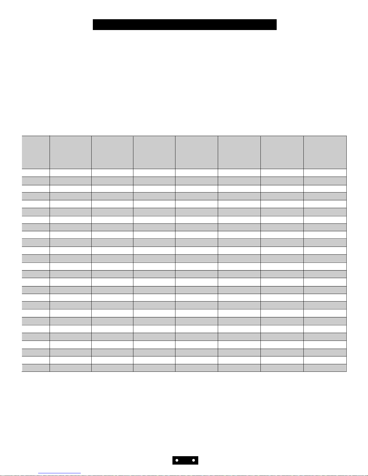
The capacity of a battery is the total amount of electrical
energy available from a fully charged cell or cells. Its
value depends on the discharge current, the temperature
during discharge, the final (cut-off) voltage and the gen-
eral history of the battery.
Capacity, expressed in ampere-hours (AH) is the product
of the current discharged and the length of discharge
time. The rated capacity (C) of a Power-Sonic battery is
measured by its performance over 20 hours of constant
current discharge at a temperature of 68°F (20°C) to a
cutoff voltage of 1.75 volts.
As an example, Model PS-610, with a rated capacity of
1AH will deliver 50 mA (1/20 of 1AH, or 0.05C ) for 20
hours before the voltage drops from 6.45 to 5.25 volts.
By cycling the battery a few times or float charging it for
a month or two, the highest level of capacity develop-
ment is achieved. Power-Sonic batteries are fully charged
before leaving the factory, but full capacity is realized
only after the battery has been cycled a few times or been
on float charge for some time.
The table in Figure 2 shows capacities for various multi-
ples of the 20-hour discharge current.
CAPACITY
Figure 2
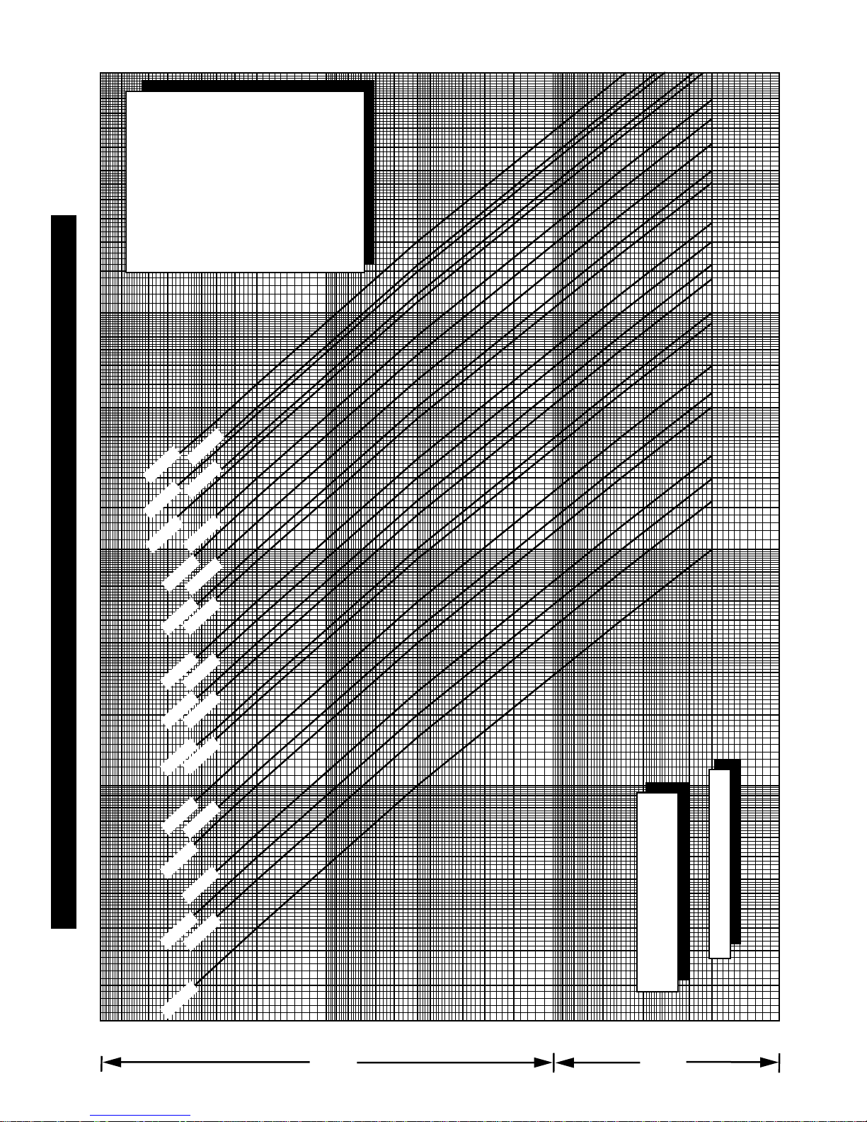
When a battery discharges at a constant rate, its capacity
changes according to the amperage load. Capacity
increases when the discharge current is less than the 20-
hour rate and decreases when the current is higher.
Figure 3 shows capacity curves for major Power-Sonic battery
models with different ampere-hour ratings. Amperage is on the
horizontal scale and the time elapsed is on the vertical scale; the
product of these values is the capacity.
Proper battery selection for a specific application can be
made from this graph if the required time and current are
known. For example, to determine the proper capacity of
a battery providing 3 amps for 20 minutes, locate the
intersection of these values on the graph. The curve
immediately above that point represents the battery
which will meet the requirement.
3

.02 .03 .05 .07 .1 .2 .3 .4 .5 .6 .8 1 2 3 4 5 6 8 10 20 30 40 50 60 80 100
6
12
18
24
30
36
42
54
1
2
3
4
5
6
7
9
10
20
30
40
50
60
80
Discharge Current (Amps)
Discharge Time
100
min hrs
0.5 AH
0.8 AH
1.0 AH
1.3 AH
2.0 AH 2.3 AH
3.0 AH
4.5 AH
5 AH
7 AH
8 AH 10 AH
12 AH
18 AH
20 AH 26 AH
33 AH 40 AH
55 AH 60 AH
80 AH
100 AH
.15 1.5 15
75 AH
CAPACITY VARIATION BY CURRENT LOAD
Discharge times reflect cut-
off voltages which vary
with the discharge current:
LOAD FINAL
CURRENT VOLTAGE
0.05C 1.75V/cell
0.10C 1.75V/cell
0.20C 1.75V/cell
0.50C 1.67V/cell
1.00C 1.50V/cell
2.00C 1.50V/cell
3.00C 1.37V/cell
“C” = Capacity of battery
Discharge time as a function
of discharge current
Ambient temp. 20°C (68°F)
Figure 3

Discharge
During discharge the voltage will decrease. The graphs in
Figure 4 illustrate this for different discharge rates and ambi-
ent temperatures. “C” is the rated capacity of a battery: “C”
for Model PS-610 (6V - 1AH) is 1AH. By convention, rating
of nearly all sealed-lead acid batteries, including Power-
Sonic, is based on a 20-hour (0.05C) discharge rate .
An important feature of Power-Sonic batteries is shown in the
discharge curves; namely, the voltage tends to remain high
and almost constant for a relatively long period before declin-
ing to an end voltage.
Figure 4: Characteristic Discharge Curves
Open-Circuit Voltage
Open circuit voltage varies according to ambient temperature
and the remaining capacity of the battery. Generally, open
circuit voltage is determined by the specific gravity of the
electrolyte. Discharging a battery lowers the specific gravity.
Consequently, it is possible to determine the approximate
remaining capacity of a battery from the terminal voltage.
The open circuit voltage of a Power-Sonic battery is
2.15 V/cell when fully charged and 1.94 V/cell when com-
13
12
11
10
9
8
0
6.5
6.0
5.5
5.0
4.5
4.0
1 2 3 5 10 20 30 102 3 5 20 30
60
min h
Discharge Time @ 20°C (68°F)
0.05C
0.1C0.175C
0.25C
0.6C
1C
2C
3C
Battery Voltage (V)
13
12
11
10
9
8
0
6.5
6.0
5.5
5.0
4.5
4.0
1 2 3 5 10 20 30 102 3 5 20 30
60
min h
Discharge Time @ 0°C (32°F)
0.05C
0.1C
0.175C
0.25C
0.6C
1C
2C
3C
Battery Voltage (V)
pletely discharged.
As seen in Figure 4, under load, the battery can deliver use-
ful energy at less than 1.94 V/cell, but after the load is
removed the open circuit voltage will “bounce back” to volt-
ages shown in Figure 5, dependent upon residual capacity.
Figure 5: Open-Circuit Voltage Characteristics
Temperature
Actual capacity is a function of ambient temperature and rate of
discharge. At 68°F (20°C) rated capacity is 100%. The capacity
increases slowly above this temperature and decreases as the
temperature falls. Even at -40°F (-40°C), however , the Power-
Sonic battery will still function at better than 30% of its rated
capacity when discharged at the 20-hour rate (0.05C). At any
ambient temperature, the higher the rate of discharge, the lower
the available capacity. This relationship is shown in Figure 6.
Power-Sonic batteries may be discharged at temperatures rang-
ing from -40°F to 140°F (-40°C to 60°C) and charged at tem-
peratures from -4°F to 122°F (-20°C to 50°C).
While raising ambient temperature increases capacity, it also
decreases useful service life. It is estimated that battery life is
halved for each 10°C above normal room temperature.
Figure 6: Effect of Temperature on Capacity
120
0
Temperature (°C)
100
80
60
40
20
-20 -10 0 10 20 30 40 50 60
Capacity Ratio (%)
0.05C
0.1C
0.25C
0.6C
1C
2C
13.5
Residual Capacity (%)
13.0
12.5
12.0
11.5
6.8
6.6
6.4
6.2
6.0
5.8
0 20 40 60 80 10
0
Ambient Temperature 77°F (25°C)
Terminal Voltage
PERFORMANCE DATA
5

Figure 7 shows the relationship between current and dis-
charge time for different ambient temperatures.
Figure 7: Discharge Time vs. Discharge Current
Shelf Life & Storage
Low internal resistance and special alloys in the electrodes
assure a low self discharge rate and, consequently, a long
shelf life. If kept at 68°F (20°C), about 60-70% of the nomi-
nal capacity remains after one year of storage. One recharge
per year is sufficient to maintain the original capacity of a
battery not in use.
The rate of self discharge varies with the ambient tempera-
ture. At room temperature it is about 3% per month. At low
temperatures it is nearly negligible, at higher ambient tem-
peratures self discharge increases.
Figure 8: Self Discharge Characteristics
To obtain maximum battery life and performance, batteries
should be:
• recharged as soon as possible after each use and
not stored in a discharged state;
• stored at 68°F (20°C) or lower, if possible, and
• recharged annually when not used.
0.05C0.1C 0.2C 0.5C 1C 2C 5C
20
15
10
5
2
1
30
10
5
Discharge Current (A)
Discharge Time
min hrs
C = Rated Capacity
Final
Voltage
1.75V/Cell
1.70V/Cell
1.60V/Cell
1.50V/Cell
1.35V/Cell104°F (40°C)
68°F (20°C)
32°F ( 0°C
100
80
60
40
00 2 4 6 8 10 12 14 16 18 20
Storage Period (Months)
Capacity Retention Ratio
Charging is no
necessary unle
100% of capaci
required.
Charging befor
e
is necessary t
o
recover full
capacity.
Charge may fai
restore full c
a
Do not let bat
reach this sta
40°C
(104°F) 30°C
(86°F) 20°C
(68°F)
5°C
(41°F)
Battery Life
Cyclic Use: The number of charge/discharge cycles depends
on the capacity taken from the battery (a function of discharge
rate and depth of discharge), operating temperature and the
charging method.
Figure9shows the relationship between depth of discharge and
number of cycles as well as increases of capacity during the
early cycles.
Figure 9: Depth of Discharge vs. Number of Cycles
Standby Use: The float service life, or life expectancy under
continuous charge, depends on the frequency and depth of
discharge, the charge voltage, and the ambient temperature.
At a float voltage of 2.25V to 2.30V/cell and an ambient tem-
perature of 60°F to 77°F (20°C to 25°C) Power-Sonic batter-
ies should last four to five years before the capacity drops to
60% of its original rating.
Figure 10 indicates how capacity changes over time.
Figure 10: Life Characteristics in Standby Use
Discharge Depth 100%
120
0
Number of Cycles
100
80
60
40
20
0 200 400 600 800 1000
Capacity (%)
1200
1. Discharge Current 0.2C
(Final Voltage 1.7V/Cell)
2. Charge Current: 0.1C
3. Ambient Temperature: 20°C to
( 68°F to 77°
F
Discharge Depth 50%
Discharge Depth 30%
Ambient Temperature 20°C (68°F)
0
Years
100
80
60
40
20
013
Retention Capacity (
%
4
Float Charging Voltage
2.25 - 2.30V/Cell
2
PERFORMANCE DATA
6

The graph in Figure 11 shows life characteristics in float
(standby) service for ambient temperatures ranging from
15°C to 55°C
If prevailing ambient temperatures are well above 20-
25°C the life expectancy of this type of battery in float
service depends greatly on temperature compensated
charging. The typical temperature coefficient is -
2mV/cell/°C. The graph shown along side is based on
temperature compensated charging.
.2
.3
.4
.5
.6
.7
.8
1
2
3
6
7
8
10
20
4
5
20°30°40°50°60°
End of life defined as
60% of rated capacity
Service Life at Various Ambient Temperatur
Temperature (C°)
Service Life (Years)
Figure 11: Service Life at Various Ambient Temperatures
To optimize battery life, it is recommended that the bat-
tery be disconnected from the load when the end voltage
– a function of the discharge rate – is reached. It is the
voltage point at which 100% of the usable capacity of the
battery has been consumed or continuation of the dis-
charge is useless because of the voltage dropping below
useful levels. (see section on Deep Discharge on page 3)
Discharging a sealed lead-acid battery below this voltage
or leaving a battery connected to a load will impair the
battery’s ability to accept a charge. To prevent potential
over-discharge problems, voltage cut-off circuits as
shown in Figure 12 may be used.
LOAD
RY
R
R
RY
NVR
Tr.
C
VR
ZD
BATT
LOAD
RY
NVR
C
BATT
RY
ZD
Figure 12: Circuits of Over-Discharge Preventive Device
Dependable performance and long service life depend
upon correct charging. Faulty procedures or inadequate
charging equipment result in decreased battery life
and/or unsatisfactory performance. The selection of suit-
able charging circuits and methods is as important as
choosing the right battery for the application.
General
To charge a Power-Sonic battery, a DC voltage higher than
the open-circuit voltage of 2.15 is applied to the terminals
of the battery. Depending on the state of charge, the cell
may temporarily be lower (after discharge) or higher (right
after charging) than 2.15 volts. After some time, however,
it should level off at about 2.15 volts per cell.
Power-Sonic batteries may be charged by using any of
the conventional charging techniques. To obtain maxi-
mum service life and capacity, along with acceptable
recharge time and economy, constant voltage-current
limited charging is recommended.
During charge, the lead sulfate of the positive plate
becomes lead dioxide. As the battery reaches full charge,
the positive plate begins generating dioxide causing a
sudden rise in voltage. A constant voltage charge, there-
fore, allows detection of this voltage increase and thus
control of the charge amount.
PERFORMANCE DATA
CHARGING
OVER-DISCHARGE PROTEC-
7

Overcharging: As a result of too high a charge volt-
age excessive current will flow into the battery after
reaching full charge causing decomposition of water in
the electrolyte and, hence, premature aging.
At high rates of overcharge a battery will progressively
heat up. As it gets hotter, it will accept more current,
heating up even further. This is called thermal runaway,
and can destroy a battery in as little as a few hours.
Undercharging: If too low a charge voltage is
applied, the current flow will essentially stop before the
battery is fully charged. This allows some of the lead sul-
fate to remain on the electrodes which will eventually
reduce capacity.
Batteries which are stored in a discharged state, or left on
the shelf for too long, may initially appear to be “open
circuited” or will accept far less current than normal.
This is caused by a phenomenon called “sulfation”.
When this occurs, leave the charger connected to the bat-
tery. Usually, the battery will start to accept increasing
amounts of current until a normal current level is
reached. If there is no response, even to charge voltages
above recommended levels, the battery may have been in
a discharged state for too long to recover.
Charging Characteristics
During constant voltage or taper charging, the battery’s
current acceptance decreases as voltage and state of
charge increase. The battery is fully charged once the
current stabilizes at a low level for a few hours.
Caution: Never charge or discharge a battery in a her-
metically sealed enclosure. Batteries generate a mixture
of gases internally. Given the right set of circumstances,
such as extreme overcharging or shorting of the battery,
these gases might vent into the enclosure and create the
potential for an explosion when ignited by a spark.
If in doubt, or concepts of proper use and care are
unclear, contact Power-Sonic’s department for applica-
tion engineering at 619-661-2020.
Please note that there are two criteria for determining
when a battery is fully charged: (1) the final current level
and (2) the peak charging voltage while this current
flows.
Figure 13 depicts an example of typical charge charac-
teristics for cycle service where charging is non-continu-
ous and peak voltage can, therefore, be higher.
Figure 13: Charge characteristics
for 14.7V Constant Voltage
Figure 14 illustrates typical characteristics for standby
service type charge. Here, charging is continuous and the
peak charge voltage must, therefore, be lower.
Figure 14: Charge Characteristics
for 13.65V Constant Voltage
Charging Methods
Selecting the appropriate charging method depends on
the intended use (cyclic or float service), economic con-
siderations, recharge time, anticipated frequency and
depth of discharge, and expected service life. The key
goal of any charging method is to control the charge cur-
rent at the end of the charge.
Taper Charging: This is the simplest, least expensive
charging method. Either quasi-constant voltage or quasi-
constant current characteristics can be built into the
charger through combination of transformer, diode and
resistance. Of the two, constant potential charging is
preferable.
15
13
11
00 5 10 15 20 25
Charge Time (h)
Battery Voltage (V)
Charge Current (A)
Charge Quantity (%)
14
12
10
1.4
1.0
0.6
0.2
0
1.2
0.8
0.4
140
100
60
20
0
120
80
40
1. Battery PS-1270
2. Discharge
100% (0.05C X 20h
)
50% (0.05C X 10
h
3. Charge
Charge voltage 13.65 (2.
2
Charge current 0.1C
4. Temperature 20°C (68°F)
Battery Voltage
Charge current
C
h
a
r
g
e
q
u
a
n
t
i
t
y
(
t
o
d
i
s
c
h
a
r
g
e
q
u
a
n
t
i
t
y
r
a
t
i
o
15
13
11
00 5 10 15 20 25
Charge Time (h)
Battery Voltage (V)
Charge Current (A)
Charge Quantity (%)
14
12
10
1.4
1.0
0.6
0.2
0
1.2
0.8
0.4
140
100
60
20
0
120
80
40
1. Battery PS-1270
2. Discharge
100% (0.05C X 20h
)
50% (0.05C X 10
h
3. Charge
Charge voltage 14.7 (2.
Charge current 0.1C
4. Temperature 20°C (68°F)
Battery Voltage
Charge current
Cha
r
g
e
q
u
a
n
t
i
t
y
(
t
o
d
i
s
c
h
a
r
g
e
q
u
a
n
t
i
t
y
)
r
a
t
i
o
CHARGING
8

Typical taper chargers are comprised of small trans-
former-rectifier circuits wherein the transformer is so
designed that the current is limited to the maximum ini-
tial charge current for the battery. This current is held
constant until the terminal voltage and resultant current
demand reach a point at which the charge current begins
to fall. Although this type of charger can provide a rela-
tively fast recharge, it is basically a constant current
device and the charge voltage may be driven too high.
Therefore, it must be disconnected, usually within 12-24
hours, or after 100-120% of the preceding discharge has
been returned. It is also sensitive to line voltage varia-
tions which can cause over- or under-charging.
Consequently, this charging method can only be used in
cyclic applications
Figure 15 shows an example of a typical diagram and
Figure 16 the resultant charge characteristics for this
type of basically unregulated charger.
Figure 15: Semi-Constant Current Charging Circuit
Figure 16: Semi-Constant Current Charge
Characteristics
Constant Current Charging: Constant current charg-
ing is suited for applications where discharged ampere-
hours of the preceding discharge cycle are known.
Charge time and charge quantity can easily be calculated,
however an expensive circuit is necessary to obtain a
highly accurate constant current. Monitoring of charge
voltage or limiting of charge time is necessary to avoid
excessive overcharge.
While this charging method is very effective for recover-
ing the capacity of a battery that has been stored for an
extended period of time, or for occasional overcharging
to equalize cell capacities, it lacks specific properties
required in today’s electronic environment.
An example of a constant current charge circuit is shown
in Figure 17 and the charge characteristics for this type
of charger in Figure 18.
Figure 17: Constant Current Charging Circuit
Figure 18: Constant Current Charge Characteristics
Constant Voltage Charging: Constant current/con-
stant voltage charging is the best method to charge
Power-Sonic batteries. Depending on the application,
batteries may be charged either on a continuous or non-
continuous basis. In applications where standby power is
required to operate when the AC power has been inter-
rupted, continuous float charging is recommended. Non-
continuous cyclic charging is used primarily with
portable equipment where charging on an intermittent
basis is appropriate.
TR
D
Charge Current
Battery Voltage
Charge Time
Battery Voltage
Charger Current
T
D1
R1R2R3
R4
R5D2
C1 ZD
TR2
TR1
Charge Current
Battery Voltage
Charge Time
Battery Voltage
Charger Current
CHARGING
9

The constant current/constant voltage charge method
applies a constant voltage to the battery and limits the
initial charge current. It is necessary to set the charge
voltage according to specified charge and temperature
characteristics. Inaccurate voltage settings cause over- or
under-charge. This charging method can be used for both
cyclic and standby applications.
Figures 19 and 20 illustrate examples of a constant cur-
rent/constant voltage charging circuit and charging char-
acteristics, respectively. The circuit diagram includes a
temperature compensation feature for charge voltage to
ensure optimum charging conditions regardless of
changes in ambient temperature.
Figure 19: Constant Current/Constant Voltage
Charge Circuit
Figure 20: Constant Current/Constant Voltage
Charge Characteristics
Charging for Cycle Operation
Cyclic applications generally require that recharging be
done in a relatively short time. The initial charge current,
however, must not exceed 0.20 x C amps. Just as battery
voltage drops during discharge, it slowly rises during
charge. Full charge is determined by voltage and inflow-
ing current. When, at a charge voltage of 2.45 ±0.05
volts/cell, the current accepted by the battery drops to
less than 0.01 x C amps (1% of rated capacity), the bat-
tery is fully charged and the charger should be discon-
nected or switched to a float voltage of 2.25 to 2.30
volts/cell. The voltage should not be allowed to rise
above 2.45 ±0.05 volts/cell.
Charging for Standby Operation
Standby applications generally do not require that the
battery be charged as fast or as frequently as in cycle
operation. However, the battery must be kept constantly
charged to replace the energy that is expended due to
internal loss and deterioration of the battery itself.
Although these losses are very low in Power-Sonic bat-
teries, they must be replaced at the rate the battery self-
discharges; at the same time the battery must not be
given more than these losses or it will be overcharged.
To accomplish this, a constant voltage method of charg-
ing called “float charging” is used.
The recommended constant float voltage is 2.25-2.30
volts per cell. Maintaining this float voltage will allow
the battery to define its own current level and remain
fully charged without having to disconnect the charger
from the battery. The trickle current for a fully charged
battery floating at the recommended charge voltage will
typically hover around the 0.001C rate (10mA for a
10AH battery, for example.)
The float charger is basically a constant voltage power
supply. As in cycle chargers, however, care must be exer-
cised not to exceed the initial charge current of 0.20
x C amperes.
Two-Step Constant Voltage Charging
This method uses two constant voltage devices. In the
initial charge phase the high voltage setting is used.
When charging is nearly complete and the charge voltage
has risen to a specified value (with the charge current
decreased), the charger switches the voltage to the lower
setting. This method allows rapid charging in cycle or
float service without the possibility of overcharging even
after extended charging periods.
The graph in Figure 21 shows charging characteristics,
and the diagram in Figure 22 an example of a charging
circuit for this type of charger.
Figure 21: Two-Step Constant Voltage
Charge Characteristics
+
–V1 V0
A
13
U1 LM317TB D5 +
R1
240
RS
Select
R 4
1.2K
R5
390
R2
D2
1N4148
R3
Q1
PN2222
C1
BR1
–
22.275V/cell
DC to Battery
float application
2.45V/cell
cyclic application
Charge Current
Battery Voltage
Charge Time
Battery Voltage
Charger Current
Charge Current
Battery Voltage
Charge Time
Battery Voltage
Charger Current
CHARGING
10

Figure 22: Dual Stage Current Limited Battery Charger
Charging in Series: Lead-acid batteries are strings of 2
volt cells connected in series, commonly 2, 3 ,4 or 6 cells
per battery. Strings of Power-Sonic batteries up to 48
volts and higher may be charged in series safely and effi-
ciently. However, as the number of batteries in series
increases, so does the possibility of slight differences in
capacity. These differences can result from age, storage
history, temperature variations or abuse.
When a single constant voltage charger is connected
across an entire high voltage string, the same current
flows through all cells in the string. Depending on the
characteristics of the individual batteries, some may
overcharge while others remain in a slightly under-
charged condition. When charging high voltage strings
this way for extended periods it is generally recommend-
ed to use a low input voltage inverter to enhance service
life and simplify charging requirements.
If one cell is lower in capacity than the others when dis-
charging a long string in series, it may actually reverse
polarity even though the total voltage of the string is at
or above the cut-off voltage.
To minimize the effects of individual battery differences,
use batteries of the same age and history and, if possible,
charge in strings of no greater than 24 or 48 volts.
Charging in Parallel: Power-Sonic batteries may
be used in parallel with one or more batteries of equal
voltage.
When connected in parallel, the current from a charger
will tend to divide almost equally between the batteries.
No special matching of batteries is required. If the bat-
teries of unequal capacity are connected in parallel, the
current will tend to divide between the batteries in the
ratio of capacities (actually, internal resistances).
When charging batteries in parallel, where different
ratios of charge are to be expected, it is best to make pro-
visions to assure that the currents will not vary too much
between batteries. Holding a small resistance in series
with each battery is all that is needed
Temperature Compensation
Power-Sonic batteries perform well both at low and high
temperatures. At low temperatures, however, charge effi-
ciency is reduced; at temperatures above 45°C, charge
efficiency increases so rapidly that there is a danger of
thermal runaway if temperature compensation is not pre-
cise.
The effect of temperature on charge voltage is less criti-
cal in float applications, than in cyclic use where rela-
tively high charge currents are applied for the purpose of
short recharge times.
Temperature effects should definitely be considered
when designing or selecting a charging system. As a rule
of thumb, temperature compensation is desirable in the
charging circuit when operating outside the range of
41°F to 95°F (5°C to 35°C) prevailing ambient. The tem-
perature coefficient is -2mV/cell/°C below 20°C in
standby service and -6mV/cell/°C below 20°C in cyclic
use. For higher temperatures the charge voltage should
be correspondingly decreased.
The table in Figure 23 lists recommended charge volt-
ages for different temperatures.
AMBIENT CHARGE VOLTAGE PER CELL
TEMPERATURE Cyclic use Float Use
-4 °F( -20 °C) 2.67-2.77V 2.34-2.39V
14 °F( -10 °C) 2.61-2.71V 2.32-2.37V
32 °F( 0 °C) 2.55-2.65V 2.30-2.35V
50 °F(+10 °C) 2.49-2.59V 2.28-2.33V
68 °F(+20 °C) 2.43-2.53V 2.26-2.31V
77 °F(+25 °C) 2.40-2.50V 2.25-2.30V
86 °F(+30 °C) 2.37-2.47V 2.24-2.29V
104 °F(+40 °C) 2.31-2.41V 2.22-2.27V
122 °F(+50 °C) 2.25-2.35V 2.20-2.25V
Figure 23: Temperature Compensated Charge Voltage
+
–V1 V0
A
13
U1 LM317TB D1 +
R1
240
RS
Select
1.2K
R5
390
R2
D2
1N4148
R3
Q1
PN2222
C1
BR1
–
R4
D3
R6
RISW
Q2
22.275 V/cell
for float applications
2.45 V/cell
for cyclic applications
Temperature compensated @ 2 mV/cell/C
Select Rs to give correct float voltage at
desired min. current: 0.6/R3= Imax.
Select Risw to turn on Q2 at
desired current Isw = Risw/0.6
CHARGING
11

Power-Sonic rechargeable sealed lead-acid batteries
are designed to provide years of dependable service.
Adherence to the following guidelines in system
design will ensure that battery life is maximized and
operation is trouble-free.
• Continuous over-or undercharging is the single worst
enemy of a lead-acid battery. Caution should be exer-
cised to ensure that the charger is disconnected after
cycle charging, or that the float voltage is set correctly.
• Batteries should not be stored in a discharged state or
at elevated temperatures. If a battery has been discharged
for some time or the load was left on indefinitely, it may
not readily take a charge. To overcome this, leave the
charger connected and the battery should eventually
begin to accept charge.
• Avoid exposing batteries to heat! Care should be taken
to place batteries away from heat-emitting components.
If close proximity is unavoidable, provide ventilation.
Service life is shortened considerably at ambients above
30°C.
• Although Power-Sonic batteries have a low self-dis-
charge rate which permits storage of a fully charged bat-
tery for up to a year, it is recommended that a battery be
charged 6-9 months after receipt to account for storage
from the date of manufacture to the date of purchase.
Otherwise, permanent loss of capacity might occur as a
result of sulfation. To prolong shelf life without charg-
ing, store batteries at 50°F (10°C) or less.
• Fasten batteries tightly and make provisions for shock
absorption if exposure to shock or vibration is likely.
• Although it is possible to charge Power-Sonic batter-
ies rapidly, i.e. in 6-7 hrs., it is not normally recom-
mended. Unlimited current charging can cause increased
off-gassing and premature drying. It can also produce
internal heating and hot spots resulting in shortened ser-
vice life. Too high a charge current will cause a battery
to get progressively hotter. This can lead to “thermal run-
away” and can destroy a battery in as little as a few
hours.
• Caution: Never charge or discharge a battery in an air-
tight enclosure. Batteries generate a mixture of gases
internally. Given the right set of circumstances such as
extreme overcharging or shorting of the battery, these
gases might vent into the enclosure and create the poten-
tial for an explosion when ignited by a spark. Generally,
ventilation inherent in most enclosures is sufficient to
avoid problems.
• Do not place batteries in close proximity to objects
which can produce sparks or flames, and do not charge
batteries in an inverted position.
• When charging batteries in series (positive terminal of
one battery is connected to the negative terminal of
another), all batteries in the string will receive the same
amount of charge current, though individual battery volt-
ages may vary.
• When charging batteries in parallel (positive terminals
are connected to the positive terminal and negative ter-
minals to the negative), all batteries in the string will
receive the same charge voltage but the charge current
each battery receives will vary until equalization is
reached.
• High voltage strings of batteries in series should be
limited to twenty 6 volt or ten 12 volt batteries when a
single constant voltage charger is connected across the
entire string . Differences in capacity can cause some
batteries to overcharge while others remain undercharged
thus causing premature aging of batteries. It is, therefore,
not advisable to mix batteries of different capacities,
make, or age in a series string.
To minimize the effects of cell or battery differences,
charge the string in 24 volt battery groups through a con-
stant current source with zener diode regulation across
individual batteries or battery groups.
• To prevent problems arising from heat exchange
between batteries connected in series or parallel, it is
advisable to provide air space of at least 0.4” (10mm)
between batteries.
• Battery containers, made of ABS plastic or styrene,
can sustain damage if exposed to organic solvents or
adhesives.
• Recharge time depends on the depth of the preceding
discharge and the output current of the charger. To deter-
mine the approximate recharge time of a fully discharged
battery, divide the battery’s capacity (amp. hrs.) by the
rated output of the charger (amps.) and multiply the
resulting number of hours by a factor of 1.75 to com-
pensate for the declining output current during charge. If
the amount of amp. hrs. discharged from the battery is
known, use it instead of the battery’s capacity to make
the calculation.
• For best results and generally acceptable performance
and longevity, keep operating temperature range between
-20°C and +40°C.
• Do not attempt to disassemble batteries. Contact with
sulfuric acid may cause harm. Should it occur, wash skin
or clothes with liberal amounts of water. Do not throw
batteries into fire; batteries so disposed may rupture or
explode. Disassembled batteries are hazardous waste and
must be treated accordingly. It is unlawful to dispose of
batteries except through a recycling center.
APPLICATION NOTES
12

Ambient Temperature
The prevailing surface temperature to which a battery is
exposed.
Ampere
Unit of measurement for electric current.
Ampere-Hour
The product of current (amperes) multiplied by time (hours).
Used to indicate the capacity of a battery. Also Amp.Hr. or A.H.
Battery
Two or more cells connected together, most typically in series.
Capacity
The electrical energy available from a cell or battery expressed
in ampere-hours.
Available capacity refers to ampere-hours that can be dis-
charged from a battery based on its state of charge, rate of dis-
charge, ambient temperature, and specified cut-off voltage.
Rated capacity (“C”) is the discharge capacity the manufacturer
says may be obtained at a given discharge rate and temperature.
Cell
The basic building block of a battery. The nominal voltage of a
lead-acid battery is 2 volts.
Cell reversal –the act of driving a cell into reverse polarity by
excessive discharge.
Primary cell –cell or battery that can be discharged only once.
Secondary cell – the process is reversible so that charging and
discharging may be repeated over and over.
Charge
The conversion of electrical energy to chemical energy; the
process which restores electrical energy to a cell or battery.
Charge retention refers to a battery’s ability to hold a charge. It
diminishes during storage.
Charge acceptance quantifies the amount of electric charge
which accumulates in a battery.
Float charge maintains the capacity of a cell or battery by
applying a constant voltage.
Trickle charge maintains the capacity of a cell or battery by
applying a small constant current.
Charge equalization brings all of the cells in a battery or string
to the same state of charge.
Discharge
The process of drawing current from a battery.
Deep Discharge – the discharge of a cell or battery to between
80% and 100% of rated capacity.
Depth of Discharge – the mount of capacity – typically
expressed as a percentage – removed during discharge.
Self Discharge –the loss of capacity while stored or not in use.
Self Discharge Rate – the percent of capacity lost on open cir-
cuit over a specified period of time.
Electrode
Positive or negative plate containing materials capable of react-
ing with electrolyte to produce or accept current.
Energy Density
Ratio of battery energy to volume or weight expressed in watt-
hours per cubic inch or pound.
Gas Recombination
The process by which oxygen gas generated from the positive
plate during the final stage of charge is absorbed into the nega-
tive plate, preventing loss of water.
Impedance
The resistive value of a battery to an AC current expressed in
ohms (Ω). Generally measured at 1000 Hz at full charge.
Internal Resistance
The resistance inside a battery which creates a voltage drop in
proportion to the current draw.
Nominal Voltage / Nominal Capacity
The nominal value of rated voltage / the nominal value of rated
capacity. The nominal voltage of a lead-acid battery is 2 volts
per cell.
Open Circuit Voltage
The voltage of a battery or cell when measured in a no load con-
dition.
Parallel Connection
Connecting a group of batteries or cells by linking all terminals
of the same polarity. This increases the capacity of the battery
group.
Series Connection
The connection of a group of cells or batteries by linking termi-
nals of opposite polarity. This increases the voltage of the bat-
tery group.
Separator
Material isolating positive from negative plates. In sealed lead-
acid batteries it normally is absorbent glass fiber to hold the
electrolyte in suspension.
SLA Battery
Sealed lead-acid battery, generally having the following charac-
teristics: Maintenance-free, leak-proof, position-insensitive.
Batteries of this type have a safety vent to release gas in case of
excessive internal pressure build-up. Hence also the term: Valve
regulated battery.
“Gel Cells” are SLA batteries whose dilute sulfuric acid elec-
trolyte is immobilized by way of additives which turn the elec-
trolyte into a gel.
Standby Service
An application in which the battery is maintained in a fully
charged condition by trickle of float charging.
State of Charge
The available capacity of a battery at a given time expressed as
a percentage of rated capacity.
Thermal Runaway
Acondition in which a cell or battery on constant potential
charge can destroy itself through internal heat generation.
GLOSSARY

Primary Power
• Portable Tools & Instruments
• Hand-held Lights
• Cordless & Portable Cellular Phones
• Power Packs
• Remote or Portable Data Gathering Devices
• Medical Apparatus
• Battery Powered Wheelchairs, Ride-on Toys
• Engine Starting Devices
• Robotics
• Consumer Electronics
• Hobby Craft
Standby Power
• UPS Systems
• Emergency Lighting
• Fire & Burglar Alarm Systems
• Access Control Devices
• Telecommunications Equipment
• Electronic Equipment Requiring Memory Protection
• Solar Powered Systems
• Automotive Electronics
SALES & MARKETING
POWER-SONIC CORPORATION
P.O. Box 5242
Redwood City, CA 94063 USA
Telephone: (650) 364-5001
Fax: (650) 366-3662
OPERATIONS & WAREHOUSE
POWER-SONIC CORPORATION
9163 Siempre Viva Road
San Diego, CA 92173
Telephone: (619) 661-2020
Fax: (619) 661-3650
EUROPE
POWER-SONIC EUROPE LTD.
3 Buckingham Square, Hurricane way
Wickford, Essex SS11 8YQ, England
Telephone: (1268) 560686
Fax: (1268) 560902
PRINTED IN USA 25M 6/98
http://www.power-sonic.com
E-mail: [email protected]
This manual suits for next models
68
Table of contents
Other Power-Sonic Camera Accessories manuals