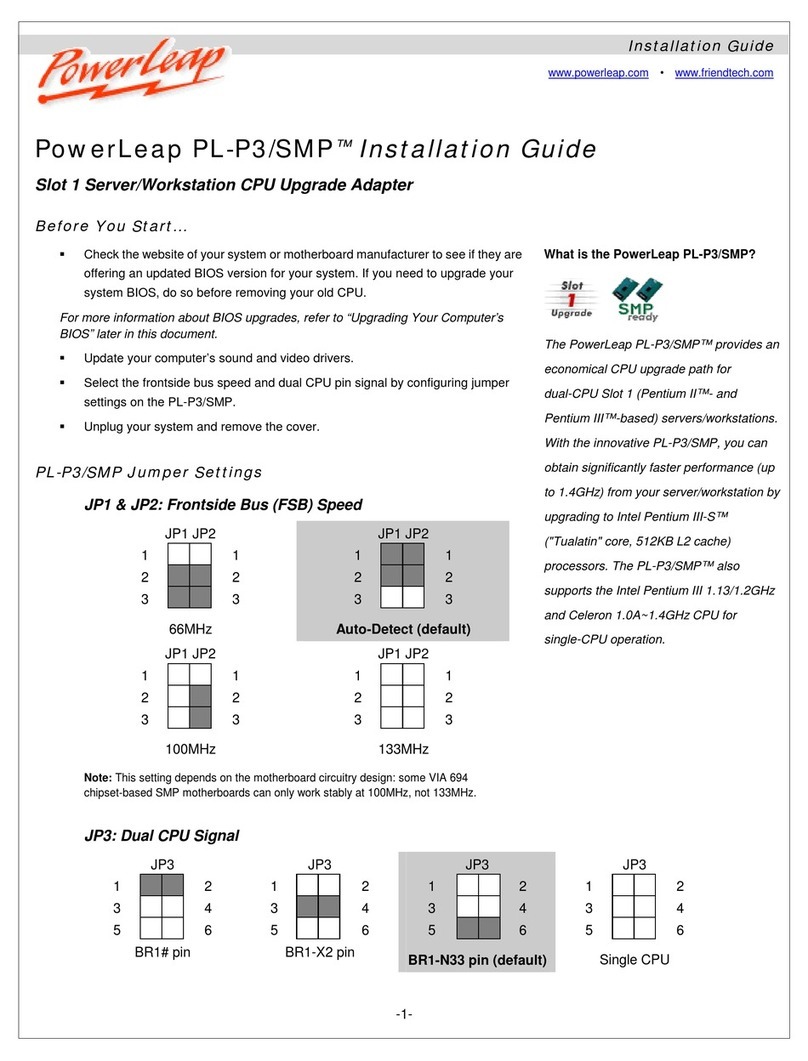
Powerleap PL-iP3 User manual

POWERLEAPPL-iP3
Pentium
III/Celeron CPU Upgrade
--for--
Slot 1 (242-Contact Slot Connector) Systems
Version 1.0

Copyright 2000 PowerLeap Products, Inc.
All Rights Reserved.
July 2000
The information in this document is subject to change without prior notice in order to improve reliability,
design, and function and does not represent a commitment on the part of the manufacturer. In no event
will the manufacturer be liable for direct, indirect, special, incidental, or consequential damages arising out
of the use or inability to use the product or documentation, even if advised of the possibility of such
damages.
PowerLeap is a registered trademark of PowerLeap Products, Inc. PL-iP3, Neo S370, PL-PII,
PL-ProMMX, IPS, PL-54C/MMX, PL-C6/200, PL-OD54C, PL-386, and PL-586 are trademarks of
PowerLeap Products Inc. Intel, MMX, and Pentium are registered trademarks of Intel Corporation.
Microsoft, Windows, Windows NT, and MS-DOS are either trademarks or registered trademarks of
Microsoft Corporation. Other product names mentioned herein are used for identification purposes only
and may be trademarks and/or registered trademarks of their respective companies.
This product employs the following PowerLeap patented technologies: US Patent 5,919,259; US Patent
5,938,769; and Japanese Registered Utility Model No. 3042946.
Visit our Web sites at:
http://www.powerleap.com
http://www.friendtech.com
The PowerLeap Web site (http://www.powerleap.com/download.htm) contains links to utility files
available for FTP download.

Introduction i
PowerLeap™Installation Guide
Table of Contents
Introduction 1
PowerLeap™ PL-iP3 Special Features ___________________________ 1
About the IntelPentium III__________________________________ 1
About the Intel Celeron_____________________________________ 2
About the FC-PGA and PPGA Form Factors _____________________ 2
What You Have ____________________________________________ 2
Before You Begin 3
Identifying Motherboard Frontside Bus (FSB) Speed ________________ 3
Determining CPU Frontside Bus (FSB) Rating and V/Core Voltage_____ 4
Locating Pin 1 on your CPU and ZIF Socket ______________________ 5
Determining CPU Performance ________________________________ 5
Configuring the PowerLeap™PL-iP3 7
Setting Jumper Switches ______________________________________ 7
Selecting Frontside Bus (FSB) Speed_____________________________ 8
Selecting Voltage___________________________________________ 11
Enabling Multiple Processors _________________________________ 13
About the Power-on LED Function ____________________________ 14
About the PowerLeap Redundant Overheating Protection Function____ 15
Installing the PowerLeap™PL-iP3 17
Removing the Existing CPU __________________________________ 17
Installing your CPU into the PL-iP3 ____________________________ 18

ii Introduction
PowerLeap™Installation Guide
Installing the CPU Heatsink/Fan ______________________________ 20
Completing the Installation of the PL-iP3________________________ 21
Upgrading Your Computer’s BIOS_____________________________ 23
Using the PL-iP3 Without the Retention Cartridge _________________ 24
FAQ 27

Introduction 1
PowerLeap™Installation Guide
Introduction
Your PowerLeap™ PL-iP3 CPU upgrade employs patented technologies (additional
patents pending) to adapt Slot 1 systems to the voltage and pinout requirements of the
new generation of IntelPentium III (FC-PGA) and Celeron™ (FC-PGA and
PPGA) processors. By providing an upgrade solution that would otherwise require the
replacement of the motherboard, PowerLeaplets you enjoy the most cost-effective
computer upgrade.
PowerLeap™ PL-iP3 Special Features
z Provides a CPU upgrade for Slot 1 (242-contact slot connector) systems.
z Supports the IntelPentium III FC-PGA CPU and the IntelCeleron CPU (FC-
PGA and PPGA form factors).
z Supports 66/100/133MHz frontside bus (FSB).
z Provides a Power-on LED indicator for maximum safety.
z Includes PowerLeap’s unique Redundant Overheating Protection function.
z When used with SMP-compliant* Celeron (PPGA) CPUs, provides dual-CPU
support on dual-Slot 1 motherboards.
* Not all Intel CPUs are SMP-compliant. To determine if you have SMP-compliant CPUs, check the
Intel web site (you will need to know the “stepping” of your CPUs).
z Supports multiple voltage settings for V/Core (1.5V, 1.65V, and 2.0V).
z Includes patented external power source technology to allow older motherboards
to use the latest 1.5V and 1.65V CPUs.
z Provides a power connector for a heatsink/fan.
z Includes a retention cartridge for easy and secure installation.
z Supports VRM 8.4, 8.3, 8.2, and 8.1.
About the IntelPentium III
The IntelPentium III is the successor to the Pentium II, incorporating the latest
technologies for enhanced video, sound, and 3D performance. Conceived to take
advantage of its new Internet Streaming SIMD Extensions and Dual Independent Bus

2 Introduction
PowerLeap™Installation Guide
(DIB) architecture, the Pentium III includes a 32KB level-one cache and a 256 KB
on-die integrated full-speed level-two cache.
About the Intel Celeron
The Intel Celeron(FC-PGA and PPGA form factors) extends the performance of
Pentium II processors with a high-performance 128KB level-two cache and 32KB
level-one cache (consisting of separate 16KB instruction and 16KB data caches).
Unlike the original Pentium II’s cache, the Celeron’s 128KB cache is built into the
processor die and so runs at full processor speed.
About the FC-PGA and PPGA Form Factors
The FC-PGA (“Flip Chip” Pin Grid Array) form factor is a chip packaging designed
for Intel Pentium III “Coppermine” processors and newer Celeron CPUs. On the FC-
PGA package, the processor’s silicon core faces up, and is exposed. This allows the
core to have direct contact with a heatsink/fan.
FC-PGA PPGA
Intel Celeronprocessors are available in the FC-PGA and PPGA (Plastic Pin Grid
Array) form factors. Both are compatible with the 370-pin socket on the PL-iP3. With
the PPGA package, the CPU’s silicon core faces down, toward the socket.
What You Have
Your PowerLeap™ PL-iP3 package includes the PowerLeap™ PL-iP3 CPU upgrade,
retention cartridge, heatsink/fan, power supply cable, and PowerLeap CPU Control
Panel software.
CPU Die
Ex
p
osed
CPU Die
Hidden

Before You Begin 3
PowerLeap™Installation Guide
Before You Begin
In order to configure your PL-iP3 properly, it is important to first gather the following
information about your system and new CPU:
• Motherboard frontside bus (FSB) speed or frequency (66, 100, or
133MHz)
• CPU FSB rating (66, 100, or 133MHz)
• CPU V/Core Voltage (Celeron 1.5, 1.65, or 2.0V; Pentium III 1.65V)
Identifying Motherboard Frontside Bus (FSB) Speed
The frontside bus (also known as the “system bus”) is the pathway between the CPU
and the computer’s main memory. Your motherboard’s FSB speed can be determined
from your motherboard documentation, by contacting your motherboard
manufacturer, or by checking the chipset installed on your motherboard.
In addition to the motherboard’s supported frontside bus speed, you will need to
know the method that the board provides for setting the FSB speed. Your
motherboard may either provide jumper switches for setting the FSB speed or offer
“jumperless” speed configuration. For “jumperless” configuration, some
motherboards allow configuration in BIOS; other boards automatically set the FSB
speed to the FSB rating of the CPU. The method that the board provides for setting the FSB
speed will determine the frontside bus speed setting that you choose on the PL-iP3 (for details, refer
to the next chapter of this manual).

4 Before You Begin
PowerLeap™Installation Guide
Determining CPU Frontside Bus (FSB) Rating and V/Core Voltage
Intel sets Pentium III and Celeron CPUs for operation at certain frontside bus speeds.
For example, the Pentium III can operate with a frontside bus speed of 100MHz or
133MHz. With current Celeron CPUs you are limited to using a frontside bus speed
of 66MHz—even if your motherboard supports a higher bus speed.
Information concerning your CPU FSB rating and CPU V/Core voltage can be
found on a black label attached to the face plate of your new Intelprocessor, as
shown below. If your CPU faceplate does not show information in the manner
shown, please check your CPU documentation or contact Intel for the
information.
This black label contains a wealth of information about your CPU including clock
speed, the size of your L2 cache, FSB rating, and your CPU V/Core voltage. In the
above example, the Celeron CPU shown on the left has an FSB rating of 66MHz and
the CPU V/Core voltage is 1.5V.
FSB
Ratin
g
CPU
Clock Speed
L2 Cache CPU
Voltage

Before You Begin 5
PowerLeap™Installation Guide
Locating Pin 1 on your CPU and ZIF Socket
All Pentium III and Celeron FC-PGA CPUs use a small orange triangle to indicate the
location of pin 1. On the corner to the right of pin 1 is an orange dot. On the PPGA
Celeron, pin 1 is indicated by an indented corner. Pin 1 corners are used to properly
align the joining of the CPU to the ZIF socket.
Pin3 1 Pin 1
FC-PGA Pin 1 PPGA Pin 1
Determining CPU Performance
To compare the performance increase provided by the PL-III, we suggest running the
PowerLeap CPU Control Panel®both before and after installation. If you are
uncertain about the speed of your existing CPU, you can determine the speed by
running the PowerLeap CPU Control Panel®. The CPU Control Panelis included
with your PL-iP3 and is also available free for downloading from the PowerLeap
website (http://www.powerleap.com).

6 Before You Begin
PowerLeap™Installation Guide

Configuring the PowerLeap™ PL-iP3 7
PowerLeap™Installation Guide
Configuring the PowerLeap™PL-iP3
This chapter lists jumper settings for selecting the frontside bus speed (FSB); selecting
the CPU V/Core voltage; and using multiple processors with your PowerLeap™
PL-iP3s. It also discusses the Power-On LED and Redundant Overheating Protection
functions.
Setting Jumper Switches
You can configure operating characteristics of the PL-iP3 by setting jumper switches
(consist of pin headers and plastic connecting caps) on the board. For convenience,
the PL-iP3 uses jumper caps of different color to specify different functions. The
jumper switches are shown in the graphic below.
FSB
Jumpers Voltage
Jumpers
SMP Enable
J
um
p
er
Connection for Fan
Connection for Power Suppl
y
PL-iP3 Jumpers Diagram

8 Configuring the PowerLeap™ PL-iP3
PowerLeap™Installation Guide
A jumper switch is ‘closed’ with the plastic cap inserted over two header pins, and
‘open’ with the plastic cap inserted over one or no pin(s).
1
2
3
4
5
6
Closed O
p
en
Pins 5-6 are closed
Pins 1-2 and 2-3
are open
Note: When a jumper is open, keep the plastic cap inserted over
one pin of the jumper so that you don’t lose it.
The PL-iP3’s jumper switches are factory preset to default settings. If you want to
change the jumper settings, refer to the following sections of this chapter to
understand the jumper functions.
Selecting Frontside Bus (FSB) Speed
To get the best CPU performance, you can use jumper switches on the PowerLeap™
PL-iP3 to set the frontside bus speed. The PL-iP3’s default FSB speed setting is
66MHz.
Note: Although an incorrect FSB setting will not damage your
CPU or your PowerLeap upgrade, it can have a serious effect on
performance.
The setting that you choose on the PL-iP3 for the frontside bus (FSB) speed depends
on several factors:
• Your motherboard’s supported FSB speed;
• Your CPU’s FSB rating; and
• The method that the motherboard provides for setting FSB speed.

Configuring the PowerLeap™ PL-iP3 9
PowerLeap™Installation Guide
As mentioned in the previous chapter, the method that your motherboard provides
for setting the FSB speed will determine the frontside bus speed setting that you
choose on the PL-iP3.
• If your motherboard has jumper switches for setting the FSB speed, the
PL-iP3’s jumper switches (JP1 and JP2) will override the motherboard
settings on the condition that the motherboard’s FSB speed jumpers are set to
“automatic”. If the motherboard’s FSB setting is set to a specific speed, the
PL-iP3’s speed setting will have no effect (be overridden).
• If your motherboard offers “jumperless” speed configuration through
settings in BIOS, the PL-iP3’s speed setting will have no effect (be
overridden).
• If your motherboard offers “jumperless” speed configuration by
automatically setting the FSB speed to the FSB rating of the CPU, you can
use the PL-iP3’s jumper switches (JP1 and JP2) to change the FSB speed.
FSB
Jumpers
JP1
FSB Jumpers Location Diagram
For Celeron users: Intel has set the FSB rating for Celerons to 66MHz. Please select
the 66MHz setting (the default) shown below.
JP1 JP2
Closed Closed
FSB Setting
for 66MHz

10 Configuring the PowerLeap™ PL-iP3
PowerLeap™Installation Guide
Regardless of your motherboard’s potential FSB speed, the
Celeron CPU will not function correctly with an FSB speed greater
than 66MHz.
For Pentium III users: You can use the PL-iP3’s jumper switches to change the FSB
speed from the default setting (66MHz) if either of the following conditions is true:
• Your motherboard has jumper switches for setting the FSB speed, and the
motherboard’s FSB speed jumpers are set to “automatic”.
• Your motherboard offers “jumperless” speed configuration by automatically
setting the FSB speed to the FSB rating of the CPU.
Otherwise, the PL-iP3’s FSB speed setting will have no effect (the motherboard’s FSB
speed setting will override the PL-iP3’s setting).
Your choice will also be determined by the supported FSB speed of your
motherboard and the FSB rating of the processor (100 or 133MHz). Your actual FSB
speed and its setting will be based on whichever speed is lower. For example, if your
motherboard supports an FSB speed of 100MHz and your Pentium III CPU has a
FSB rating of 133MHz, you should set the FSB speed to 100MHz. If your
motherboard supports 133MHz but your CPU is only rated for 100MHz, you should
also set the FSB speed to 100MHz.
Setting FSB Speed for Pentium III CPUs
1. Determine your motherboard’s FSB speed.
2. Determine your CPU’s FSB rating.

Configuring the PowerLeap™ PL-iP3 11
PowerLeap™Installation Guide
3. Configure your PL-iP3 jumper switches according to the appropriate photo shown
below.
JP1 JP2
Closed Closed
Closed Open
JP1 JP2
Open Open
JP1 JP2
Selecting Voltage
Your voltage selection is determined by the voltage printed on the faceplate of your
CPU or as specified in your CPU documentation.
CAUTION! It is imperative that you use the correct jumper setting
for the appropriate voltage of your CPU. An incorrect setting may
cause serious damage to your CPU and/or your PL-iP3. Please
take a moment to verify your CPU’s voltage before continuing.
V
oltage
Jumpers
JP 3 456
7
JP11
Voltage Jumpers Location Diagram
FSB Setting
for 66MHz
FSB Setting
for 100MHz
FSB Setting for
133MHz

12 Configuring the PowerLeap™ PL-iP3
PowerLeap™Installation Guide
• For Celeron users please select 1.5V (the default setting), 1.65, or 2.0V.
1.5V Celeron (FC-PGA):
JP3 JP4 JP5 JP6 JP7
JP11
1
2
3
5
4
6
Closed Closed Closed
Closed
Open
Open
Open
Open
1.65V Celeron (FC-PGA):
JP3 JP4 JP5 JP6 JP7
JP11
1
2
3
5
4
6
Closed Closed Open Open
Open
Open
Closed
Closed
Note: If your Celeron documentation indicates a V/Core of 1.7V,
please set the jumpers (as shown above) for 1.65V. This setting will
not affect your CPU’s health or performance.

Configuring the PowerLeap™ PL-iP3 13
PowerLeap™Installation Guide
2.0V Celeron (PPGA):
JP3 JP4 JP5 JP6 JP7 JP11
21
3
5
4
6
OpenOpenOpen Open
Open
Open
Closed
Closed
• All Pentium III users please select 1.65V.
JP3 JP4 JP5 JP6 JP7
JP11
1
2
3
5
4
6
Note: If your Pentium III documentation indicates a V/Core of
1.6V, please set the jumpers (as shown above) for 1.65V. This
setting will not affect your CPU’s health or performance.
Enabling Multiple Processors
The PL-iP3 supports dual processing for SMP-enabled* Celeron (PPGA) CPUs.
Symmetric Multi-Processing (SMP) is a method allowing the use of multiple-
processors in a single computer system. If your computer system does not have
slots for multiple CPUs, please disregard this section.
* Not all Intel CPUs are SMP-compliant. To determine if you have SMP-compliant CPUs, check the
Intel web site (you will need to know the “stepping” of your CPUs).

14 Configuring the PowerLeap™ PL-iP3
PowerLeap™Installation Guide
By default, dual processing is enabled for PPGA Celeron CPUs (we recommend
leaving the JP8 jumper switch at the default setting).
SMP Enable
Jumper
SMP Enable Jumper Location Diagram
SMP enabled for
PPGA Celeron CPU
s
JP8
1
2
3
About the Power-on LED Function
To ensure the safety of your upgrade components, PowerLeap provides the Power-On
LED function. This safety feature enables you to determine whether or not power is
flowing through the PL-iP3 and helps prevent costly damage to both your expensive
CPU and the upgrade board itself.
Caution! Never insert nor remove your CPU from the PL-iP3 when
the Power-On LED is on. Inserting or removing your CPU from
the PL-iP3 while the power is on can damage your sensitive and
expensive CPU.

Configuring the PowerLeap™ PL-iP3 15
PowerLeap™Installation Guide
About the PowerLeap Redundant Overheating Protection Function
As CPU clock speeds increase, so do CPU temperatures that can potentially damage
your system’s most vital component. The PL-iP3 includes our unique Redundant
Overheating Protection function, which can help prevent damage to your CPU if the
temperature increases to a potentially unsafe level.
65
CPU Temperature (degrees Celsius)
100%
70 75 80 85 90 95
50%
75%
25%
At under 70 degrees,
CPU operates at 100% speed
6055
CPU Speed
55
At 70 degrees,
CPU speed drops to 50%
At 85 degrees,
CPU speed drops to 25%
This function automatically reduces the CPU speed when the temperature gets too
hot, thus keeping the computer running long enough for you to save your work and
gracefully shut down. This protection function is automatically enabled—it is
not necessary to configure jumper settings.
Note: To take full advantage of this feature, we recommend
running the PowerLeap CPU Control Panel software (you may
want to set it to start automatically with Windows). Doing so will
enable you to enjoy special features including an on-screen
warning that the CPU temperature has exceeded safe levels.

16 Configuring the PowerLeap™ PL-iP3
PowerLeap™Installation Guide
Table of contents
Other Powerleap Computer Hardware manuals
Popular Computer Hardware manuals by other brands

Glunz & Jensen
Glunz & Jensen 68 Silver manual

Fuji Electric
Fuji Electric OPC-VG1-DIO instruction manual

Polon-Alfa
Polon-Alfa POLON 4000 Series Installation and maintenance manual

SIIG
SIIG CyberParallel ExpressCard Quick installation guide

SUNRICH TECHNOLOGY
SUNRICH TECHNOLOGY C-330 user manual

Lenovo
Lenovo ThinkServer 5500 Series Brochure & specs