PowerOptimal Elon 100 User manual

© PowerOptimal (Pty) Ltd 2017. The content of this document is confidential and all rights to the intellectual
property and/or information contained herein remain vested in PowerOptimal, except if otherwise agreed in
writing.
PowerOptimal Elon 100 Installation and User Manual
Version number: 1.19
Enquiries: info@poweroptimal.com
Address: PO Box 39521
Capricorn Square
7948
Cape Town

© PowerOptimal (Pty) Ltd 2017. The content of this document is confidential and all rights to the intellectual
property and/or information contained herein remain vested in PowerOptimal, except if otherwise agreed in
writing.
SAFETY WARNING
•Installation of the Elon 100 should ONLY be performed by an electrical
contractor registered with the Department of Labour (the so-called
“wireman’s licence”) and strictly according to the installation instructions
in this manual. The electrician should provide you with a Certificate of
Compliance (CoC) once installation is completed.
•We strongly recommend that you use a reputable and experienced solar
photovoltaic (PV) system installer to install your solar PV modules.
•Solar PV modules exposed to the sun are live (i.e. will produce electricity)
and can give an electric shock. Special care should be taken and only
trained solar PV installers should install the modules.
•Do not attempt to alter or service the electrical installation, or open the
Elon 100 unit or controller for any purpose.
•Use the Elon 100 only for its intended purpose.
•Always make sure that every wiring connection is properly tightened.
•Do not earth either of the solar module wires (but do earth the frames).
•All installation wiring should be at least 2.5mm².
•Avoid coiling, since DC switching can create damaging spikes.
•Keep all wires as short as possible.

© PowerOptimal (Pty) Ltd 2017. The content of this document is confidential and all rights to the intellectual
property and/or information contained herein remain vested in PowerOptimal, except if otherwise agreed in
writing.
Refer to our online instruction video for
easy to understand instructions on how to
use the PowerOptimal ElonTM 100:
www.poweroptimal.com/elon100

PowerOptimal ElonTM 100 Installation & User Manual
DATE: 18/09/2017
Page 4 of 31
Version: 1.19
© PowerOptimal (Pty) Ltd 2017. The content of this document is confidential and all rights to the intellectual
property and/or information contained herein remain vested in PowerOptimal, except if otherwise agreed in
writing.
Table of Contents
Table of Contents....................................................................................................................................4
1. Introduction ........................................................................................................................................5
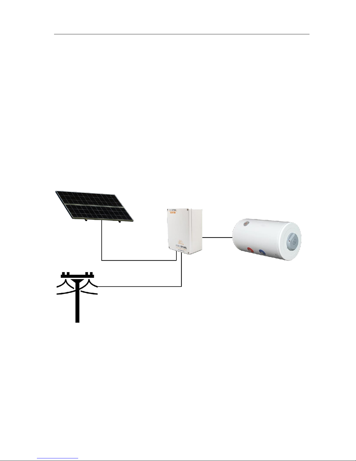
1.1 System overview ...........................................................................................................................5
1.2 Main system components.............................................................................................................6
1.3 Deciding on size of Elon system (basic guide)...............................................................................6
1.4 Deciding on size of solar array (expert guide) .............................................................................. 6
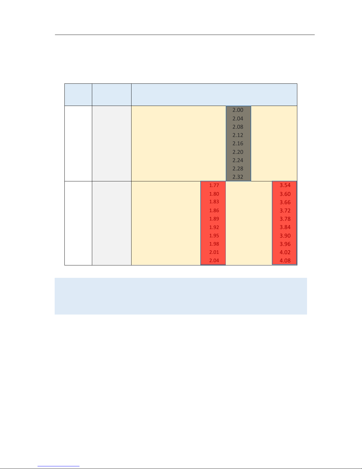
1.5 PV array and geyser (water heater) element matching (expert guide)......................................11
2. Installation ........................................................................................................................................12
2.1 Required tools.............................................................................................................................12
2.2 Basic wiring diagram ...................................................................................................................13
2.3 Solar PV array installation...........................................................................................................14
2.4 Elon 100 installation....................................................................................................................16
2.5 Element installation (retrofit) .....................................................................................................16
3. Operation..........................................................................................................................................17
3.1 Elon 100 Controller .....................................................................................................................17
3.2 Mains / solar indicator lights ......................................................................................................17
3.3 Efficiency dial ..............................................................................................................................17
3.4 Override button ..........................................................................................................................18
3.5 How to maximise your savings....................................................................................................18
4. Maintenance .....................................................................................................................................20
4.1 Solar PV module maintenance....................................................................................................20
5. Basic troubleshooting .......................................................................................................................21
Appendix A. Solar yield .........................................................................................................................23
A1. Solar irradiance levels.................................................................................................................23
A2. Geographic features ...................................................................................................................24
A3. Azimuth / horizontal angle .........................................................................................................24
A4. Inclination or tilt angle................................................................................................................24
A5. Shading .......................................................................................................................................24
A6. Ambient temperature.................................................................................................................25
Appendix B. Technical Specification: Elon 100 .....................................................................................26
Appendix C. IEC/SANS Test Certificate: Elon 100..................................................................................27
Appendix D. Warranty ..........................................................................................................................28
Appendix E. Terminology......................................................................................................................29
Notes.....................................................................................................................................................31

PowerOptimal ElonTM 100 Installation & User Manual
DATE: 18/09/2017
Page 5 of 31
Version: 1.19
© PowerOptimal (Pty) Ltd 2017. The content of this document is confidential and all rights to the intellectual
property and/or information contained herein remain vested in PowerOptimal, except if otherwise agreed in
writing.
1. Introduction
Thank you for buying the PowerOptimal ElonTM 100 solar PV water heating unit! You can look forward
to many years of savings and free energy from the sun.
1.1 System overview
The PowerOptimal Elon 100 operates on a very simple principle: it enables direct current (DC)
electricity produced by solar PV modules to be used directly for water heating using a standard geyser
with alternating current (AC) heating element and AC thermostat.
You can connect the system completely off-grid, or integrate with your existing grid AC power supply.
Connecting the system to the existing grid supply allows for grid power backup in case of cloudy /
overcast days, or where your hot water use exceeds the generation capacity of your solar PV array.
Note: the system is designed in such a way that there is no possibility of solar array-produced
electricity feeding back into the grid.
Below is a simplified layout of the main components of the water heating system.
An array of solar modules (a string of 3 to 6 solar modules connected in series, or two parallel strings
of 4, 5 or 6 solar modules each) is connected to the Elon 100. Grid electricity is also connected to the
Elon 100.
The Elon 100 is connected to the geyser element and thermostat.
When the solar modules are producing electricity, the Elon 100 feeds this into the geyser element to
heat water, until the water reaches the temperature setting on the thermostat.
Depending on the Elon 100 efficiency setting (see Section 3.3) or when the user presses the override
button, the Elon 100 will boost the water heating with grid electricity.

PowerOptimal ElonTM 100 Installation & User Manual
DATE: 18/09/2017
Page 6 of 31
Version: 1.19
© PowerOptimal (Pty) Ltd 2017. The content of this document is confidential and all rights to the intellectual
property and/or information contained herein remain vested in PowerOptimal, except if otherwise agreed in
writing.
1.2 Main system components
The main components of the system are as follows:
•Solar modules with struts, brackets and cabling
•PowerOptimal Elon unit with controller
•Existing or new water heater or geyser (hot water tank with AC heating element and AC
thermostat)
•Isolators for grid and solar connections
1.3 Deciding on size of Elon system (basic guide)
The table below provides a basic guide to selecting the size of your Elon system based on number of
people in the household and/or hot water use. Refer to Sections 1.4 and 1.5 for a detailed guide (for
solar PV experts).
Elon kit
Showers
per day*
No. of people
50%+ of hot
water use
No. of
people
off-grid
Solar PV
array size
kWp
Geyser
element
kW
Geyser (water
tank) size
litres
Kit 1 –Solar Boost
3 –4
2-3
1-2
1.5 –1.7
2
100 –150
Kit 2 –Solar Living
5 –6
3-4
2-3
2.4 –2.7
4
150 –200
Kit 3 –Solar Pro
7 –8
4-5
3-4
3 –3.5
4
200 +
* 6-minute showers at 40 ºC with 8 litre/min (low-flow) showerheads
1.4 Deciding on size of solar array (expert guide)
Solar power is generated by solar cells, which are arranged in framed modules, typically of 60 or 72
cells each. The total set of solar PV modules installed on your rooftop is referred to as a solar PV array
1
.
1
Image source: http://ohioline.osu.edu/factsheet/AEX-652-11.

PowerOptimal ElonTM 100 Installation & User Manual
DATE: 18/09/2017
Page 7 of 31
Version: 1.19
© PowerOptimal (Pty) Ltd 2017. The content of this document is confidential and all rights to the intellectual
property and/or information contained herein remain vested in PowerOptimal, except if otherwise agreed in
writing.
TABLE 1. ANNUAL AVERAGE LITRES OF WATER HEATED PER DAY
The below example table indicates the average number of litres of water per day that the system will
heat from 15 to 60 °C over a year period for different solar array peak power ratings. (The amount of
water heated will vary with weather conditions, by geographic location and by season. Water heated
per day will be significantly lower in winter and significantly higher in summer. These numbers indicate
heating capacity –i.e. if no hot water is used on a given day, there will be less water heated on that
day. This is only an approximate guide.)
Solar + Elon
Annual average litres of water heated per day for X kWpinstalled solar capacity
Location
kWh/kWp/yr
0.8 kWp
1 kWp
1.2 kWp
1.4 kWp
1.6 kWp
1.8 kWp
2 kWp
2.5 kWp
3 kWp
3.5 kWp
Bloemfontein
1894
80
99
119
139
159
179
199
249
298
348
Cape Town
1624
68
85
102
119
136
154
171
213
256
299
Durban
1447
61
76
91
106
122
137
152
190
228
266
Jhb/Pretoria
1724
72
91
109
127
145
163
181
226
272
317
Mbombela
1627
68
85
103
120
137
154
171
214
256
299
Port Elizabeth
1565
66
82
99
115
132
148
164
205
247
288
Upington
1912
80
100
121
141
161
181
201
251
301
352
Saldanha
1623
68
85
102
119
136
153
170
213
256
298
Example:
For a solar array of 1.2 kWp, an installation in Johannesburg would yield about 1724 kWh/kWp/yr, or
1724 x 1.2 kWp= 2069 kWh/yr. This would be sufficient to heat on average 109 litres of water per
day. For a family of 2 each using 80 litres of hot water per day, this would provide about 109 ÷ (80 x 2)
or 68% of the annual hot water requirement.

PowerOptimal ElonTM 100 Installation & User Manual
DATE: 18/09/2017
Page 8 of 31
Version: 1.19
© PowerOptimal (Pty) Ltd 2017. The content of this document is confidential and all rights to the intellectual
property and/or information contained herein remain vested in PowerOptimal, except if otherwise agreed in
writing.
TABLE 2. ANNUAL AVERAGE NUMBER OF SHOWERS PER DAY
The below table indicates the average number of showers per day for which the system will supply
hot water over a year period for different solar array peak power ratings. (The amount of water heated
will vary with weather conditions, by geographic location and by season. Water heated per day will be
significantly lower in winter and significantly higher in summer. These numbers indicate heating
capacity –i.e. if no hot water is used on a given day, there will be less water heated on that day. This
is only an approximate guide.)
Solar + Elon
Number of showers per day (based on annual average) for X kWpinstalled solar capacity
Location
kWh/kWp/yr
0.8 kWp
1 kWp
1.2 kWp
1.4 kWp
1.6 kWp
1.8 kWp
2 kWp
2.5 kWp
3 kWp
3.5 kWp
Bloemfontein
1894
2.4
3.0
3.6
4.2
4.8
5.4
6.0
7.5
9.0
10.4
Cape Town
1624
2.0
2.6
3.1
3.6
4.1
4.6
5.1
6.4
7.7
9.0
Durban
1447
1.8
2.3
2.7
3.2
3.6
4.1
4.6
5.7
6.8
8.0
Jhb/Pretoria
1724
2.2
2.7
3.3
3.8
4.3
4.9
5.4
6.8
8.2
9.5
Mbombela
1627
2.1
2.6
3.1
3.6
4.1
4.6
5.1
6.4
7.7
9.0
Port Elizabeth
1565
2.0
2.5
3.0
3.5
3.9
4.4
4.9
6.2
7.4
8.6
Upington
1912
2.4
3.0
3.6
4.2
4.8
5.4
6.0
7.5
9.0
10.5
Saldanha
1623
2.0
2.6
3.1
3.6
4.1
4.6
5.1
6.4
7.7
9.0
The table is based on 6-minute showers at 40 °C and 8 litres/min low flow showerheads. Old
showerheads can use up to 15 litres/min and would substantially reduce the number of showers.
Example:
For a solar PV array of 2.5 kWp, an installation in Johannesburg would yield about 1724 kWh/kWp/yr,
or 1724 x 2.5 kWp= 4 310 kWh/yr. This would be sufficient for about 6 to 7 showers per day.

PowerOptimal ElonTM 100 Installation & User Manual
DATE: 18/09/2017
Page 9 of 31
Version: 1.19
© PowerOptimal (Pty) Ltd 2017. The content of this document is confidential and all rights to the intellectual
property and/or information contained herein remain vested in PowerOptimal, except if otherwise agreed in
writing.
TABLE 3. PERCENTAGE OF ANNUAL HOT WATER REQUIREMENT
The below example table indicates what % of the annual hot water requirement will on average be
supplied by the system for 2 people each using 80 litres of hot (60 °C) water per day. (The amount of
water heated will vary with weather conditions, by geographic location and by season. Water heated
per day will be significantly lower in winter and significantly higher in summer. These numbers indicate
heating capacity –i.e. if no hot water is used on a given day, there will be less water heated on that
day. This is only an approximate guide.)
Solar + Elon
Annual average % of hot water requirement supplied for 2 people each using 80 litres of hot
water per day for X kWpinstalled solar capacity
Location
kWh/kWp/yr
0.8 kWp
1 kWp
1.2 kWp
1.4 kWp
1.6 kWp
1.8 kWp
2 kWp
2.5 kWp
3 kWp
3.5 kWp
Bloemfontein
1894
50%
62%
75%
87%
99%
112%
124%
155%
187%
218%
Cape Town
1624
43%
53%
64%
75%
85%
96%
107%
133%
160%
187%
Durban
1447
38%
47%
57%
66%
76%
85%
95%
119%
142%
166%
Jhb/Pretoria
1724
45%
57%
68%
79%
91%
102%
113%
142%
170%
198%
Nelspruit
1627
43%
53%
64%
75%
85%
96%
107%
134%
160%
187%
Port Elizabeth
1565
41%
51%
62%
72%
82%
92%
103%
128%
154%
180%
Upington
1912
50%
63%
75%
88%
100%
113%
126%
157%
188%
220%
Saldanha
1623
43%
53%
64%
75%
85%
96%
107%
133%
160%
186%
Examples:
An array of 1.2 kWpwill provide approximately 64% of the annual hot water requirement for a family
of two people in Cape Town.
An array of 2 kWpwill provide approximately 124% x (4 / 2) = 62% of the annual hot water requirement
for a family of four people in Bloemfontein.

PowerOptimal ElonTM 100 Installation & User Manual
DATE: 18/09/2017
Page 10 of 31
Version: 1.19
© PowerOptimal (Pty) Ltd 2017. The content of this document is confidential and all rights to the intellectual
property and/or information contained herein remain vested in PowerOptimal, except if otherwise agreed in
writing.
TABLE 4. PEAK POWER OUTPUT FOR VARIOUS SOLAR MODULES AND ARRAY SIZES
The peak power production (Wp) of the modules at STC (Standard Test Conditions) and at NOCT
(Nominal Operating Cell Temperature) are provided by the solar PV module manufacturer. The below
table indicates the peak power at STC for a range of solar module power ratings and array sizes.
No. of cells
per module
Module STC
power rating (Wp)
Total peak power at STC in kWpfor an array of X modules
3 modules
4 modules
5 modules
6 modules
2 x 4 (8)
modules
2 x 5 (10)
modules
2 x 6 (12)
modules
60
250
0.75
1.00
1.25
1.50
2.00
2.50
3.00
60
255
0.77
1.02
1.28
1.53
2.04
2.55
3.06
60
260
0.78
1.04
1.30
1.56
2.08
2.60
3.12
60
265
0.80
1.06
1.33
1.59
2.12
2.65
3.18
60
270
0.81
1.08
1.35
1.62
2.16
2.70
3.24
60
275
0.825
1.10
1.375
1.65
2.20
2.75
3.30
60
280
0.84
1.12
1.40
1.68
2.24
2.80
3.36
60
285
0.855
1.14
1.425
1.71
2.28
2.85
3.42
60
290
0.87
1.16
1.45
1.74
2.32
2.90
3.48
72
295
0.885
1.18
1.475
1.77
2.36
2.95
3.54
72
300
0.90
1.20
1.50
1.80
2.40
3.00
3.60
72
305
0.915
1.22
1.525
1.83
2.44
3.05
3.66
72
310
0.93
1.24
1.55
1.86
2.48
3.10
3.72
72
315
0.945
1.26
1.575
1.89
2.52
3.15
3.78
72
320
0.96
1.28
1.60
1.92
2.56
3.20
3.84
72
325
0.975
1.30
1.625
1.95
2.60
3.25
3.90
72
330
0.99
1.32
1.65
1.98
2.64
3.30
3.96
72
335
1.005
1.34
1.675
2.01
2.68
3.35
4.02
72
340
1.02
1.36
1.70
2.04
2.72
3.40
4.08
Examples:
An array of 4 x 300 Wpmodules in series will have a total peak power (at STC) of 1.2 kWp.
An array of 2 parallel strings of 5 modules of 280 Wpeach (10 modules of 280 Wpin total) will have a
total peak power (at STC) of 2.8 kWp.
NOT ALLOWED
(exceeds maximum rated Elon
100 voltage)
NOT ALLOWED
(exceeds maximum rated Elon
100 voltage)
NOT RECOMMENDED
(poor matching efficiency
with heating element)

PowerOptimal ElonTM 100 Installation & User Manual
DATE: 18/09/2017
Page 11 of 31
Version: 1.19
© PowerOptimal (Pty) Ltd 2017. The content of this document is confidential and all rights to the intellectual
property and/or information contained herein remain vested in PowerOptimal, except if otherwise agreed in
writing.
1.5 PV array and geyser (water heater) element matching (expert guide)
TABLE 5. PV ARRAY AND GEYSER (WATER HEATER) ELEMENT MATCHING
It is important to match PV array specifications and heating elements for maximum power transfer
efficiency. See the below table for the recommended heating element power rating for different solar
module power ratings and array sizes.
No. of
cells
Module STC
power
rating (Wp)
Module
NOCT
Vmpp (V)
Module
NOCT
Impp (A)
Best element size match (rated power in kW @ 230 V AC) for an array of X
modules
3 modules
4 modules
5 modules
6 modules
2 x 4 (8)
modules
2 x 5 (10)
modules
2 x 6 (12)
modules
60
250 –290
28 –29
6.5 –7.3
4 kW
3 kW
2 kW
2 kW
NR
4 kW
4 kW
72
295 - 340
33 –35
6.5 –7.3
3 kW
2 kW
2 kW
NA
4 kW
4 kW
NA
* mpp = maximum power point
STC = Standard Test Conditions (irradiance 1000 W/m², spectrum AM 1.5, cell temperature 25 °C)
NOCT = Nominal Operating Cell Temperature (800 W/m², spectrum AM 1.5, cell temperature ~ 43 –45 °C)
NA = Not Allowed (exceeds maximum rated Elon 100 voltage)
NR = Not Recommended (poor array-heating element matching efficiency)
Example:
For 4 x 300 Wp(1.2 kWp) solar modules, the best heating element match is a 2 kW AC element (as
rated at 230V).
TABLE 6. ALTERNATIVE MATCHING (ABOUT 5 –10% EFFICIENCY LOSS COMPARED TO THE ABOVE
TABLE)
No. of
cells
Module STC
power
rating (Wp)
Module
NOCT
Vmpp (V)
Module
NOCT
Impp (A)
Best element size match (rated power in kW @ 230 V AC) for an array of X
modules
3 modules
4 modules
5 modules
6 modules
2 x 4 (8)
modules
2 x 5 (10)
modules
2 x 6 (12)
modules
60
250 –290
28 –29
6.5 –7.3
3 kW
2* or 4 kW
3 kW
NR
NR
NR
3 kW
72
295 - 340
33 –35
6.5 –7.3
4 kW
3 kW
3* kW
NA
NR
3 kW
NA
* Marginal (10%+ loss)
Example:
For 4 x 300 Wp(1.2 kWp) solar modules, the best heating element match is a 2 kW AC element (as
rated at 230V), but a 3 kW element can also be used. It will have about 5 - 10% efficiency loss compared
to a 2 kW element.
Contact PowerOptimal for advice on array-element matching if module properties (Vmpp and Impp at
NOCT) are significantly different to the values provided in the table.
DO NOT DEVIATE FROM THE RECOMMENDED ARRAY-ELEMENT MATCHING CONFIGURATIONS
WITHOUT CONSULTING POWEROPTIMAL.

PowerOptimal ElonTM 100 Installation & User Manual
DATE: 18/09/2017
Page 12 of 31
Version: 1.19
© PowerOptimal (Pty) Ltd 2017. The content of this document is confidential and all rights to the intellectual
property and/or information contained herein remain vested in PowerOptimal, except if otherwise agreed in
writing.
2. Installation
2.1 Required tools
The following tools are required for the installation. Use insulated tools wherever applicable.
•Solar modules (mounting) - please refer to solar module / mounting installation instructions –
the below is only a guideline:
oCordless screwdriver with bits
oDrill
oSet of drill bits (wood, steel, stone)
oSet of screwdrivers
oSet of Allen (hex) keys
oTape measure
oGrinder (tile roof installations)
oPermanent marker
oChalk
oHammer
•Solar modules (electrical):
oAC/DC Clamp meter
oSide-cutting pliers
oScrewdriver set
oCrimping tool
o4 mm² wire (double insulated) (or other size as determined by solar PV voltage and
wire length)
oCable ties
•Elon 100 - the following additional tools:
oDrill or punch (to make holes for glands)
o4 mm² wire (2-core Norsk or Surfix wire is recommended)

PowerOptimal ElonTM 100 Installation & User Manual
DATE: 18/09/2017
Page 13 of 31
Version: 1.19
© PowerOptimal (Pty) Ltd 2017. The content of this document is confidential and all rights to the intellectual property and/or information contained herein remain vested
in PowerOptimal, except if otherwise agreed in writing.
2.2 Basic wiring diagram
Note: Both AC & DC isolators should be installed within 1.5m of the geyser (water heater), line of sight.

PowerOptimal ElonTM 100 Installation & User Manual
DATE: 18/09/2017
Page 14 of 31
Version: 1.19
© PowerOptimal (Pty) Ltd 2017. The content of this document is confidential and all rights to the intellectual
property and/or information contained herein remain vested in PowerOptimal, except if otherwise agreed in
writing.
2.3 Solar PV array installation
Modules should only be installed by a trained solar PV installation technician. Array position and
orientation have a major impact on power production (see Appendix A).
Review the instructions from your solar PV module supplier / manufacturer on installation.
Please note: A South African standard for low voltage embedded generation installations is
being developed (SANS 10142:3). In the absence of this standard, your solar PV installation
technician should follow SANS 10142:1 (Standard for low voltage installations), and can refer
to interim guidelines in anticipation of the SANS 10142:3 standard –see for example the
document provided by PQRS:
http://pqrs.co.za/wp-content/uploads/2016/01/PV-System-Interim-Guidelines-Good-
Practice-for-Solar-PV-Installations-South-Africa-.pdf
SAPVIA (South African Photovoltaic Industry Association) has made available an excellent
guide to solar PV installations. See:
https://www.pvgreencard.co.za/Solar%20PV%20Guidelines%20-%20Digital%20
Spread%20High-res.pdf
The below installation steps are a general guide only –refer to the abovementioned standards and
guidelines.
1. A very important starting point is safety gear: ensure that all installers wear a helmet and
insulated safety gloves, as well as fall protection safety gear if work will be done on a roof or
elevated area.
2. The solar PV array should only consist of one string of 3 to 6 modules in series, or two parallel
strings of 8 (2 x 4), 10 (2 x 5) or 12 (2 x 6) modules as per Tables 4 to 6. Do not exceed the DC
voltage or current ratings of the Elon 100 (220V DC and 20A DC) under any circumstances.
3. Attach bracket / mounting structure to roof. Use mounting structure recommended by solar
module supplier for roof type and size of solar modules.
4. Fix the solar PV modules to the mounting structure whilst connecting the module cables to
each other.
5. If practical, cover the modules to ensure that there is no potential for electric shock whilst
installing the system.
6. Ground the mounting structure only.
7. Install the wiring from the solar PV array to the Elon 100 unit in the ceiling space. Ensure
isolators are in the “Open” position. Installation of a Surge Protective Device (SPD) between
the solar PV array and the Elon 100 is recommended.
8. Last step is to connect the array to the rest of the wiring, making sure that both the positive
and negative wires are fully isolated from ground and keeping isolators in the “Open” position.

PowerOptimal ElonTM 100 Installation & User Manual
DATE: 18/09/2017
Page 15 of 31
Version: 1.19
© PowerOptimal (Pty) Ltd 2017. The content of this document is confidential and all rights to the intellectual
property and/or information contained herein remain vested in PowerOptimal, except if otherwise agreed in
writing.
Some “DO’s & DON’T’s” when installing solar PV arrays:
Your solar PV installer should not make any of these basic mistakes, but they are listed here just in
case.
1. DO earth the PV array structure.
2. DO isolate the wires from the PV array structure.
3.
DON’T use different sizes, types or specifications of modules together in the same string or
array.
4.
DON’T install solar arrays where they will be partially shaded during any season of the year if
it can be avoided at all.
5. DO install the arrays so that there is space for inspection or maintenance when needed.
6. DO use cabling of the correct size for your solar array.
7.
DON’T install the solar array flush with your rooftop. Use struts / brackets that ensure an
unrestricted air gap of at least 40 mm between the roof and the modules.
8. DON’T walk on the modules.
9. DO ensure that connectors are kept clean and away from water.
10. DON’T leave exposed modules in short circuit.
11. DO ensure that all connectors are securely fastened.
12. DON’T exceed the voltage ratings of any components.
13. DO properly route and secure all cables.
14. DON’T coil cables.

PowerOptimal ElonTM 100 Installation & User Manual
DATE: 18/09/2017
Page 16 of 31
Version: 1.19
© PowerOptimal (Pty) Ltd 2017. The content of this document is confidential and all rights to the intellectual
property and/or information contained herein remain vested in PowerOptimal, except if otherwise agreed in
writing.
2.4 Elon 100 installation
1. Isolate the geyser –switch off the geyser circuit breaker at the main electrical distribution
board (DB) AND switch off the geyser isolator at the geyser.
2. Confirm with a multimeter that there is no voltage across the wires.
3. Install isolator for solar PV (DC) supply. Also install AC supply isolator if there is none. NB
Ensure that the DC isolator is rated for the DC voltage and current of the installed array.
4. The isolators must be installed within 1.5m of the geyser, and must be line of sight / visible
(i.e. do not install them at the back of the geyser).
5. The DC wires must not be earthed –i.e. they must be fully isolated from earth. Do NOT test
with a Megger.
6. Keep the DC wires as short as possible.
7. Avoid any coils in DC wires.
8. Recommended wiring size is 4 mm². 2-core Norsk or Surfix wire is recommended. Shield can
be earthed to PV array structure.
9. Install the Elon 100 unit according to wiring diagram (see Section 2.2). Mount the Elon 100
unit close to the geyser and protect from outside elements. Mount the controller (remote
control) inside or next to the main DB in the house.
10. Attach installation diagram sticker (as provided) to the front of the geyser or close by in a
clearly visible position.
11. Once installation is complete, switch on the AC & DC isolators, remove the covering from the
solar modules and switch on the geyser circuit breaker at the main DB.
12. Check that Elon 100 unit is operational (refer to LED lights on controller –see Section 3.2).
a. Confirm solar PV array supply voltage and DC power to geyser when thermostat is
closed. (If thermostat is not closed, open hot water tap in house until it closes.)
b. Test mains override.
c. Confirm that no power is supplied to geyser element when thermostat is open.
13. Set efficiency to desired level on controller (see Section 3.3).
Note: if doing any maintenance, rewiring or disconnecting the Elon 100 or geyser element for any
reason, it is good practice to first swith off both the AC & DC isolators, and then disconnect one of the
wires between the Elon 100 and thermostat before disconnecting the rest of the wires.
2.5 Element installation (retrofit)
If you need to exchange the element on an existing geyser (see Section 1.4), please follow the
instructions provided by the element supplier.

PowerOptimal ElonTM 100 Installation & User Manual
DATE: 18/09/2017
Page 17 of 31
Version: 1.19
© PowerOptimal (Pty) Ltd 2017. The content of this document is confidential and all rights to the intellectual
property and/or information contained herein remain vested in PowerOptimal, except if otherwise agreed in
writing.
Instruction video: www.poweroptimal.com/elon100
Refer to our easy to understand instruction video on how to use the Elon 100.
3. Operation
3.1 Elon 100 Controller
Your Elon 100 has a controller that is typically
installed next to your DB (distribution board). The
controller has three main functions:
1. Indicating heating activity through the
mains (red) & solar (green) indicator
lights
2. Setting the efficiency on the efficiency
dial.
3. Forcing the system to use grid (mains)
electricity for one heating cycle using the
override button.
3.2 Mains / solar indicator lights
The Mains & solar indicator lights indicate the following conditions:
Lights
Meaning
Mains (red) light flashing
Grid / mains electricity is being used to heat water
Solar (green) light flashing
Solar power is being used to heat water. Rate of flashing indicates
rate of solar energy supply
Red & green alternating
No power is being supplied to the geyser element. (Either the water
is on temperature already, or the unit is in solar mode and there is
not sufficient sunlight)
Red or green flashing very
fast
Isolation fault (contact electrician)
Both lights OFF
No power to unit (e.g. no sun and a power failure, or no sun and
geyser breaker at DB board is switched off)
3.3 Efficiency dial
You can use a screwdriver to turn the efficiency dial. The dial is
recessed so that people do not change the efficiency setting
unnecessarily or too frequently.
The ratio of installed solar power capacity to overall hot water use
level will determine what solar efficiency level will deliver the
maximum savings whilst ensuring hot water availability.
3.3
Efficiency
dial
3.4
Override
button
3.2 Mains
/ solar
indicator
lights

PowerOptimal ElonTM 100 Installation & User Manual
DATE: 18/09/2017
Page 18 of 31
Version: 1.19
© PowerOptimal (Pty) Ltd 2017. The content of this document is confidential and all rights to the intellectual
property and/or information contained herein remain vested in PowerOptimal, except if otherwise agreed in
writing.
At the “MINIMUM” efficiency setting, the Elon 100 will use grid power to boost the water temperature
at night, until approximately 3 am in the morning, and again from approximately 11 am onwards (“top-
up time”) if the sun is not shining.
As the efficiency is increased (by turning the efficiency dial anti-clockwise with a screwdriver), the
Elon 100 will only boost the water heating with grid power later in the day (i.e. it will give the solar
power supply more time to heat the water before boosting with grid power).
When the efficiency dial is set to “SOLAR ONLY”, the Elon 100 will ONLY use solar power to heat water.
Note that the override button is still functional at the “SOLAR ONLY” setting, in case you need to
boost water heating on a cloudy day or when using a lot of hot water.
If you set the Elon efficiency setting to “SOLAR ONLY” (highest efficiency), you can increase the geyser
thermostat temperature above 60 ºC to get maximum benefit from your solar array installation. For
example, you can set the thermostat temperature to 65 or 70 ºC.
Remember to reduce the thermostat temperature to 60 ºC again if you reduce the efficiency setting.
Warning: Do not set thermostat temperature above 70 ºC due to increased scalding risk.
Be careful when opening hot water taps located close to your geyser. You can install a
thermostatic mixing valve to reduce the risk of scalding –ask your plumber.
3.4 Override button
If you would like to override the functioning of the Elon 100 and force it to use grid power for water
heating (for example in case of prolonged cloudy weather, or having used a lot of hot water), press
and hold the override button for more than 10 seconds.
This will force the Elon 100 to switch to grid (mains) power for one heating cycle (in other words,
heating the water with grid electricity to the thermostat set point from whatever temperature it is at
the time of pressing the override button).
Only the red mains light on the controller should start flashing at this point. (If both red and green
lights are flashing (alternating), the water is already at the thermostat set point, and pressing the
override button will have no effect.)
3.5 How to maximise your savings
Efficiency dial
The best way to maximise your savings is to set the Elon efficiency dial to “SOLAR ONLY”. This will
ensure that the unit will never use grid (mains) power for heating water. You can still override / boost
with mains power (for example on a cloudy day) using the override button as described above.
If you do not have enough solar power for the number of people and overall level of hot water use in
the household, you might not reach the desired water temperature with the “SOLAR ONLY” setting,
and might need to reduce the efficiency setting, or reduce your hot water use.

PowerOptimal ElonTM 100 Installation & User Manual
DATE: 18/09/2017
Page 19 of 31
Version: 1.19
© PowerOptimal (Pty) Ltd 2017. The content of this document is confidential and all rights to the intellectual
property and/or information contained herein remain vested in PowerOptimal, except if otherwise agreed in
writing.
Please note: The water in your geyser should be heated to 60 °C at least once a week to
prevent Legionella bacterial growth
2
. If you have heavily overcast weather for more than a
week, use the override button to supplement the solar water heating with grid electricity to
reach the thermostat temperature setting.
When is the best time to shower?
If the efficiency dial is set to “SOLAR ONLY”, it is best for people in the household to shower either in
the morning or in the evening, but not both. (If you shower in the evening, cold water will mix with
the remaining warm water overnight, and you will have cold water the next morning. If you do not
shower again in the morning, the water will be heated during the day.)
If the efficiency dial is set to lower efficiency than “SOLAR ONLY”, it is best to shower in the morning
for maximum savings.
General hot water energy saving tips
•Shower, don’t bath
•Install water-saving / low flow shower heads (these also save energy because of reduced hot
water use!)
•Reduce shower duration
•Check that your geyser is well insulated
South Africa is a water-scarce country –reducing hot water use saves both energy and water!
2
See for example: http://www.eskom.co.za/sites/idm/Documents/Legionaires_Fact_sheet_hot_water
_bacteria_simple_facts.pdf and http://standards.nsf.org/apps/group_public/download.php/
30413/How%20to%20Avoid%20LD%20at%20Home.pdf

PowerOptimal ElonTM 100 Installation & User Manual
DATE: 18/09/2017
Page 20 of 31
Version: 1.19
© PowerOptimal (Pty) Ltd 2017. The content of this document is confidential and all rights to the intellectual
property and/or information contained herein remain vested in PowerOptimal, except if otherwise agreed in
writing.
4. Maintenance
The Elon 100 has been designed to last for a very long time, and has no moving parts aside from two
electrical relays. No maintenance is required on the Elon 100.
4.1 Solar PV module maintenance
It is recommended that a qualified electrician inspect your solar PV installation at least once a year.
1. At least once a week, check whether any of the indicator lights are flashing rapidly. (This
indicates an isolation fault –refer to Section 3.2.)
2. Perform regular visual checks (at least once a year). Check for soiling or any visible damage to
any of the modules.
3. If the modules have been soiled by dirt, dust, debris, bird droppings or any other materials,
use water only and a sponge or soft cloth to clean them. Do the cleaning early in the morning
or late in the afternoon, as the modules are hot during the day. Avoid using a water jet that
may leave streaks on the modules.
4. Visually inspect cables for any degradation or loose fittings.
5. Look for any shading problems, such as trees that may have grown.
6. An electrician can check solar power production on a sunny day to ensure that the system is
still producing power at expected levels. A thermal imaging camera can be used to inspect
modules for hot spots.
7. Follow any specific maintenance instructions from the solar PV module manufacturer.
Other manuals for Elon 100
4
Table of contents
Popular Water System manuals by other brands

Kenmore
Kenmore Elite ULTRAFILTER 650 625.38556 owner's manual

Everpure
Everpure Quad-MC EV9628-08 Specification sheet

Flow-Rite
Flow-Rite Pro-Fill RV Edition Installation & operation

EOS
EOS FWA 01 Compact Assembly and operating instruction

Jupiter
Jupiter JP108 Aquarius owner's manual

3M
3M 3MDW201 Installation and operating instructions