PowerStar MAX User manual

1
10.12 Powerstar MAX O&M Manual
4 Cowley Way, Ecclesfield, Sheffield, S35 1QP | T: +44 (0)1142 576200 | E: info@powerstar.com
www.powerstar.com
Powerstar is a registered trademark of EMSc (UK) Ltd | Company registration number: 4209907 | Registered in England and Wales
Operations and Maintenance Manual
Powerstar Serial Number: PS 2000 3671
Spritzer,Lot 898 Jalan Reservoir, Off Jalan Air Kuning, Malaysia
Project number: F1992
Reference number: 72

2
10.12 Powerstar MAX O&M Manual
4 Cowley Way, Ecclesfield, Sheffield, S35 1QP | T: +44 (0)1142 576200 | E: info@powerstar.com
www.powerstar.com
Powerstar is a registered trademark of EMSc (UK) Ltd | Company registration number: 4209907 | Registered in England and Wales
Contents – Powerstar MAXwithHMI
Front Page
1
Contents Page
2
General Description of Powerstar
3
Important safety Information
3
Electrical Specification
4
Conformity
4
Pre-Install/Commissioning Checks
5
Electrical Details
5
TechnicalSafety Notes
7
Technical Description
8
MainComponents
9
Operation
10
System Faults and Troubleshooting
•Fault code reporting
•System fault codes
•Fault troubleshooting
•
System fault possible causes and actions
11
Appendix
Powerstar® Test Certificate
Appendix 1
Powerstar® CertificateofConformity
Appendix2
Bolt Torque Instruction WI01-04
Appendix 3
Powerstar® MAXTestCertificate
Appendix4
Powerstar® MAX Certificate of Conformity
Appendix 5
User HMI Manual
Appendix 6
WarrantyCertificate
Appendix7

3
10.12 Powerstar MAX O&M Manual
4 Cowley Way, Ecclesfield, Sheffield, S35 1QP | T: +44 (0)1142 576200 | E: info@powerstar.com
www.powerstar.com
Powerstar is a registered trademark of EMSc (UK) Ltd | Company registration number: 4209907 | Registered in England and Wales
General Description
Voltage optimisation is a term given to the systematic controlled reduction of the electrical
utilities supply voltage received by an energy consumer to reduce energy use, power
demand and reactive power demand.
The Powerstar® product provides a fixed voltage reduction across a predefined tap range,
based on assessment of each individual consumers supply characteristics.
Powerstar® systems are typically installed in series between the raw mains transformer and
main low voltage distribution board allowing all of the consumer electrical equipment to
benefit from an optimised supply. Powerstar® systems can also improve power quality by
balancing phase voltages and filtering harmonics and transients from the electric utilities
supply.
Powerstar® units are manufactured and tested in compliance with BS EN 60076 using low
loss core steel, close coupled copper and high-quality components.
The units are designed for a maximum ambient temperature of 40°C at a maximum altitude
of 1000 metres above sea level and a relative humidity of 85%
The Powerstar® unit has a design life in excess of 50 years for the wound components.
Important Safety Information
Ensure any work is carried out by suitable competent and experienced personnel
Where the Powerstar® unit rating is not protected by the existing main incoming circuit
protection arrangement, suitable additional protective devices must be installed.
Before entering the Powerstar® enclosure to carry out any maintenance or cleaning tasks,
ensure that a complete isolation/lock off procedure has been carried out
Enclosure

4
10.12 Powerstar MAX O&M Manual
4 Cowley Way, Ecclesfield, Sheffield, S35 1QP | T: +44 (0)1142 576200 | E: info@powerstar.com
www.powerstar.com
Powerstar is a registered trademark of EMSc (UK) Ltd | Company registration number: 4209907 | Registered in England and Wales
The Powerstar® unit is supplied in a robust heavy weight bolt together steel floor standing,
free venting enclosure. This offers a protection of IP23 and is finished in epoxy polyester
powder coating.
Location
The Powerstar® unit is designed to be installed in line with the main incoming low voltage
supply to site/building, in a clean and dry location.
CAUTION
THE POWERSTAR® DESIGN RATING MUST NOT BE EXCEEDED
IF IN DOUBT CONTACT THE MANUFACTURER
THE AIR VENTS ON THE POWERSTAR® EQUIPMENT MUST BE KEPT CLEAR AT ALL TIMES!
Electrical Specification
Input:
415v - 3 phase – 50Hz
Output:
Input voltage less the voltage reduction which has been
specified to suit the site conditions:
12.5, 15, 17.5, 20, 25 Volt reduction range with the tap
selected by the MAX controller according to desired set point
and mains incoming voltage level
Insulation:
Class F (minimum)
Cooling:
ANAN
Screening:
An earthed copper screen is provided between windings
Electrical Connections:
Stud/bus bar (rating dependant) to connection panel on the top
of the Powerstar® unit
Thermal Indication:
PT100 temperature probes embedded within each winding leg,
individually connected and brought out to terminals on the
connection board below the top cover.
Conformity
This product complies with the directive of the Council of European Communities on the
approximation of the laws of the Member States relating to electromagnetic compatibility
(EMC Directive 2014/30/EU) and concerning electrical equipment for use within specified
voltage limits (Low Voltage Directive 2014/35/EU).
The Waste Electrical and Electronic Equipment Regulations 2012/19/EU
In compliance with the WEEE Regulations, EMSc (UK) Ltd are registered with a Producer
Compliance Scheme.

5
10.12 Powerstar MAX O&M Manual
4 Cowley Way, Ecclesfield, Sheffield, S35 1QP | T: +44 (0)1142 576200 | E: info@powerstar.com
www.powerstar.com
Powerstar is a registered trademark of EMSc (UK) Ltd | Company registration number: 4209907 | Registered in England and Wales
EMSc (UK) Ltd are BSI certified to BS EN ISO 14001:2015 and are committed to
environmental considerations.
Any Powerstar® product reaching the end of its life span can be returned for registered
disposal and/or recycling
Every Powerstar® unit is labelled with the Wheelie Bin logo and date marked.
Pre-Installation/Commissioning Checks
Ensure electrical supply is isolated prior to commencing any works
Check both inside and outside the enclosure for obvious signs of damage
Carr out insulation checks, phase to earth and phase to phase, before connecting MAX and
(after isolating HMW and/or HMI if fitted) prior to making any electrical connections
Following the connection of all conductors prior to live connection, visual checks should be
carried out to ensure no foreign material is within the transformer enclosure (including
winding area).
All electrical connections should be checked for integrity prior to live connection, in line with
EMS work instruction (Appendix 3)
Routine Inspections
It is recommended that inspections are carried out once every five years on the Powerstar®
unit, these should include:
Visual –
Signs of Damage (mechanical)
Signs of overheating (discolouration of materials/cables)
Dust build up
Indications of moisture ingress
Electrical insulation test should be carried out every 5 years
Where PPM systems use thermal imaging equipment the Powerstar® unit should be
included in the routine inspections.
All work should only be carried out by competent personnel
In contaminated environments time between inspections should be reduced accordingly.

6
10.12 Powerstar MAX O&M Manual
4 Cowley Way, Ecclesfield, Sheffield, S35 1QP | T: +44 (0)1142 576200 | E: info@powerstar.com
www.powerstar.com
Powerstar is a registered trademark of EMSc (UK) Ltd | Company registration number: 4209907 | Registered in England and Wales
Spare parts
Parts associated with the Powerstar® unit are not regarded as serviceable items, however
where spare parts are required please also quote both type and serial number from the
rating plate to ensure correct replacement parts are supplied
Contact Powerstar® on 01142576200
Electrical Details
Powerstar® units are designed to be able to offer five levels of voltage reduction. This level
of reduction is defined at the time of manufacturing and it is based on the specific site
voltages.
The MAX control system will select the appropriate tap in order to achieve the desired
output voltage at the Powerstar® load connections.
Electrical Connection/Main Power Connections (Reduction in Voltage)
S1 to Phase 1 Incoming
L1 to Phase 1 Load
S2 to Phase 2 Incoming
L2 to Phase 2 Load
S3 to Phase 3 Incoming
L3 to Phase 3 Load
N Terminal Connected to Neutral
The neutral connecting cable size should equate to the minimum 25% of main rated
current of the Powerstar®
2000VA – 2784A unit = 696amps

7
10.12 Powerstar MAX O&M Manual
4 Cowley Way, Ecclesfield, Sheffield, S35 1QP | T: +44 (0)1142 576200 | E: info@powerstar.com
www.powerstar.com
Powerstar is a registered trademark of EMSc (UK) Ltd | Company registration number: 4209907 | Registered in England and Wales
MAX
Technical Safety Notes
This description contains the necessary information for the correct operation of the product
described. It is intended for use only by technically qualified personnel.
Qualified personnel are persons who, because of their training, experience and position as
well as their knowledge of appropriate standards, regulations, health and safety
requirements and working conditions, are authorised to be responsible for the safety of the
equipment, at all times, whilst carrying out their normal duties and are therefore aware of,
and can report, possible hazards (Definition of qualified employees according to IEC364).
Safety Instructions
The following instructions are provided for the personal safety of operators and also for the
protection of the described product and connect equipment.
WARNING!
Hazardous voltages may be present!
Failure to observe safety precautions can kill or cause serious injury!
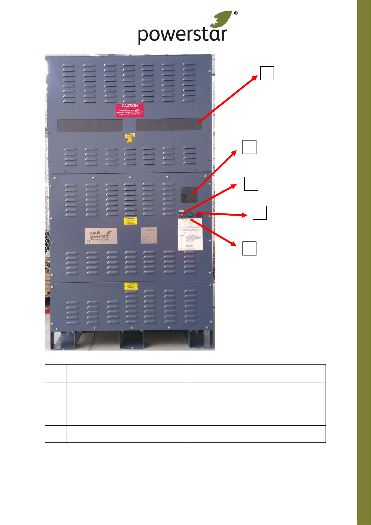
WARNING! The link connections in the upper section of the MAX unit are connected to tap
connections of the Voltage Optimiser. Therefore, when in operation the voltages at the links
can be significantly higher than the rated nominal voltage of 415v. The system must be
isolated from the supply before commencing with any servicing work!
•Isolate from mains before installation or dismantling work, or post installation
modifications
•Observe the prescribed accident prevention and safety rules for the specific
application
•Before putting into operation check if the rated voltage for the unit conforms with
the local supply
•Emergency stop must be provided for all applications
•Operation of the service input key to the zero position acts as an emergency stop to
inhibit any further uncontrolled operation
•The electrical connections must be covered
•Earth connections must be checked for safe function after assembly
Specified use
The units described herein are electrical equipment for use and installation in industrial
plant. They are NOT designed for use in domestic premises or environments.

8
10.12 Powerstar MAX O&M Manual
4 Cowley Way, Ecclesfield, Sheffield, S35 1QP | T: +44 (0)1142 576200 | E: info@powerstar.com
www.powerstar.com
Powerstar is a registered trademark of EMSc (UK) Ltd | Company registration number: 4209907 | Registered in England and Wales
Technical Description
The Powerstar® MAX System is used for controlling the voltage to a site, in conjunction with
a Powerstar® Voltage optimiser unit at continuous, full-rated current across the output
voltage range. Silicon Controlled rectifiers (Sold state devices) are used to connect to the
most appropriate of the 5 taps of the voltage optimisers control windings, which varies the
amount of voltage reduction applied to the site. The phase angle is unaffected and the
voltage sine-wave is preserved. The system also has an under-voltage protection circuit. So,
if the site conditions or grid supply voltage dips to a level low enough to effect operation of
the site, then the MAX system will automatically remove the voltage optimisation until such
time that the voltage reduction can be reapplied.
Due to the use of Solid-State devices the tap selection operation is maintenance free. In the
event of a failure of semiconductor device cooling, the unit will shut down to protect itself
and automatically generate a fault code. However, this does not negate the need for the
unit to be inspected (as for any electrical equipment). However, it is not envisaged that any
works will arise from a successful and complete inspection of the MAX system.
A rating plate is permanently fixed to the enclosure of the Powerstar® MAX system and this
is stamped with the maximum level of voltage current and powers that the MAX system is
designed for, when running continuously at an ambient temperature of less than 40°C and
an altitude of less than 1000 meters above sea level.
Note: That these ratings relate to the voltage optimiser tap control circuit not which the
MAX panel is connected.
The rated values must be reduced if these temperatures and altitude values are exceeded.
The Powerstar® MAX system cannot be used at temperatures below -10°C
The AC voltage frequency must also comply with the value on the rating plating otherwise
the Powerstar® MAX system will not operate efficiently and could be damaged through
overheating

9
10.12 Powerstar MAX O&M Manual
4 Cowley Way, Ecclesfield, Sheffield, S35 1QP | T: +44 (0)1142 576200 | E: info@powerstar.com
www.powerstar.com
Powerstar is a registered trademark of EMSc (UK) Ltd | Company registration number: 4209907 | Registered in England and Wales
PSMAXSystem
EMS Powerstar® MAX
Dynamic Voltage Control System
Nominal Input Volts: 415v
224 Amps: 3phase 50Hz
Serial Number:
Build Date:
Standards:
161kVA
ESPS890647
01/2019
BS EN 50178

10
10.12 Powerstar MAX O&M Manual
4 Cowley Way, Ecclesfield, Sheffield, S35 1QP | T: +44 (0)1142 576200 | E: info@powerstar.com
www.powerstar.com
Powerstar is a registered trademark of EMSc (UK) Ltd | Company registration number: 4209907 | Registered in England and Wales
Item
Description
Function
1
Viewing window(s)
To allow visual inspection of filter board
2
Viewing window (control board)
Allows view of BLUE fault code LED
3
Service input key
To put MAX system into and out of service
4
Status Indicator lamp 1
Displays status of unit (Software Version on
power up, On = Reduction on, Off = Reduction
off, Pulsing – Number of pulses = fault code)
5
Status Indicator lamp 2
Displays status of unit (Initialisation test on
power up, On = Fault off = healthy
Operation
1
2
3
4
5

11
10.12 Powerstar MAX O&M Manual
4 Cowley Way, Ecclesfield, Sheffield, S35 1QP | T: +44 (0)1142 576200 | E: info@powerstar.com
www.powerstar.com
Powerstar is a registered trademark of EMSc (UK) Ltd | Company registration number: 4209907 | Registered in England and Wales
The Powerstar® MAX unit operates in conjunction with a Powerstar® Voltage optimiser. The
function of the MAX unit is to automatically vary the amount of voltage reduction applied to
ensure that the site voltage is maintained at a predefined set-point. Hence, as site load
changes, or the Grid voltage fluctuates, the site voltage will be maintained at the optimum
level for energy savings to be achieved.
The operator level controls are as follows:
1. Service input key
2. HMI System
The service input key is used by the operator to put the MAX systems into service, turn the
MAX out of service and to reset a fault condition (should this ever occur).
Note: There is a 30 second time delay for the Automatic voltage reduction bypass (AVR)
before the MAX unit can be put into service. This delay is for the system to analyse the
Voltage level of the supply for under voltage condition before enabling MAX control.
The 300 second counter can be found on the voltage reduction page of the MAX HMI
Manual
Key switch position 0: with the service input key in the zero position, the Powerstar® MAX
system is offline. In this condition the site will be delivered with the fluctuating mains level
voltage.
Safety Note: In this off position, the MAX system is offline, HOWEVER the unit is still
connected electrically to the Powerstar unit, which is still connected to the site’s Electrical
supply. Hence the Powerstar® unit and the MAX system are still LIVE. Position 0 does NOT
give ant form of isolation and the whole system must be considered as being LIVE.
Key switch position 1: When the service input key is turned to 1 from the zero position, the
Powerstar® MAX system is brought on line. In this condition the site will be delivered with
the stabilised, optimised voltage to an accuracy of +/- 1.25v of set-point.
When the key turned from position 0 to position 1, the main contactor will energise
immediately. A series of internal check and parameter checks are then carried out and if all
is well, the unit will automatically energise the fail-safe contactors and switch into service
after approximately 5 seconds. When the unit is in service, tap 1 will be selected and voltage
reduction/savings will result.
If/when the AVR timer has elapsed the MAX will commence changing tap changing tap to
stabilise the site voltage.

12
10.12 Powerstar MAX O&M Manual
4 Cowley Way, Ecclesfield, Sheffield, S35 1QP | T: +44 (0)1142 576200 | E: info@powerstar.com
www.powerstar.com
Powerstar is a registered trademark of EMSc (UK) Ltd | Company registration number: 4209907 | Registered in England and Wales
Reset function: When the service input key is turned from 1 to the zero position, the
Powerstar® MAX system is taken off line. To reset a fault or lockout condition, leave the
switch at the 0 position for 30 seconds and then to position 1. The standard set of checks
will be carried out and off all faults are cleared, then the system will reset. If the fault
cannot be reset, the system will lock itself out and the RED neon indicator will illuminate.
The only option now is to report the situation to EMSc (UK) Ltd who will send a service
engineer to investigate the issues
Before contacting EMSc (UK) Ltd, please look through the control board viewing winding
and count the number of flashes from the blue LED (The LED flashes a number of times. It
then waits for two seconds and then repeats the number of flashes on a continual loop until
the fault is resolved). Please have these to hand when contacting EMSc (UK) Ltd.
System Faults and Troubleshooting
Depending on the control board software version, a number of system faults may be
detected which cause the MAX to automatically shut down into a fault state, providing no
voltage reduction. This section details these faults, alongside possible causes and solutions.
Depending on the software version of the unit, the system be capable of autonomously
resetting faults a number of times before finally going into a fault shutdown.
Fault code reporting
When in RUN/’Savings’ mode and a fault is detected the system will automatically shut
down into fault mode:
The voltage reduction performed by the voltage optimiser will be OFF and mains incoming
voltage level will be passed through to the optimiser output.
The relevant fault code will be reported using the Control Board LED D1 (Blue), visible
through the lower front panel viewing window and green lamp on the front of the cubicle.
Error! Reference source not found shows fault code pulse timings for example Fault Code 3:
‘1’ LED ON, ‘0’ = LED OFF (example below).

13
10.12 Powerstar MAX O&M Manual
4 Cowley Way, Ecclesfield, Sheffield, S35 1QP | T: +44 (0)1142 576200 | E: info@powerstar.com
www.powerstar.com
Powerstar is a registered trademark of EMSc (UK) Ltd | Company registration number: 4209907 | Registered in England and Wales
Depending on the control board software version, fault code descriptions are given in the
below table
Fault
code
Fault code list v3
Fault code list v4
Fault code list v5
1
Processor error
Processor/Temp Sensor
Error
Processor/Temp Sensor
Error
2
Supply voltage Phase
Imbalance
Supply voltage low/phase
imbalance
Supply voltage low/phase
imbalance
3
Ambient over temp
Ambient/heatsink over
temp
Ambient/heatsink over
temp
4
Supply voltage low
Fan fault
Fan/SPD/ Contactor Fault
5
Phase over current
Phase over current
Phase over current
6
Heatsink over temp
Driver fault
Neutral over current
7
Lockout trip
Lockout trip
Lockout trip
8
Control voltage low
Control voltage low
Control voltage low
9
-
Auto reset fault*
Auto reset fault*
10
-
Permanent fault*
Permanent fault*
*Fault codes 9 & 10 will always be followed by a code from 1-8 identifying the fault type;
reporting of the latter code repeats until the system is reset.
Fault Troubleshooting
The table below describes possible causes and appropriate actions for the various fault
types. The system may be manually reset from a fault by turning the key switch from
position 1 to 0
If after a system reset any of the faults are persistent, leave the system in STOP/’Bypass’
mode and contact EMSc UK with the reported fault code

14
10.12 Powerstar MAX O&M Manual
4 Cowley Way, Ecclesfield, Sheffield, S35 1QP | T: +44 (0)1142 576200 | E: info@powerstar.com
www.powerstar.com
Powerstar is a registered trademark of EMSc (UK) Ltd | Company registration number: 4209907 | Registered in England and Wales
Fault type
Possible causes
Actions
Processor/Temperature
Sensor Error
-An error has been detected
in the control board
-An internal temperature
sensor is reading below its
limit
-Check ambient temperature
-Reset the unit
-If fault persists, unit requires
service
Supply voltage
low/phase imbalance
-The supply phase voltage
magnitude has fallen below
its limit
-The supply phase voltage
imbalance has exceeded its
limit
-Check incoming
supplies/breakers
-Reset the unit
-If fault persists, unit requires
service
Ambient/heatsink over
temperature
-An internal temperature
sensor is reading above its
limit
-Allow unit to cool
-Check ambient temperature is
within specified limits
-Check that there is adequate
clearance around the unit and
that none of the air vents are
obstructed
-Reset the unit
-If fault persists, unit requires
service
Fan fault
-One of the internal fans has
malfunctioned
-Reset the unit
-If the fault persists, unit
requires service
Phase over current
-The maximum system load
limit has been exceeded
-A ‘high-inrush’ load has
caused one or more phase
currents to exceed their
limits
-A load fault has occurred
-If possible, reduce system load
-Check load circuit breakers
downstream of the unit
-Reset the unit
-If fault persists, unit requires
service
Driver Fault
-An internal hardware fault
has been detected
-Reset the unit
-If the fault persists, unit
requires service
Lockout trip
-The system controller has
lost synchronisation with the
grid
-Reset the unit
-If the fault persists, unit
requires service
Control voltage low
-The internal control voltage
has fallen below its limit
-Reset the unit
-If the fault persists, unit
requires service
This manual suits for next models
1
Table of contents
Popular Industrial Electrical manuals by other brands

Abtech
Abtech HVJB Series Installation, operation & maintenance instructions

SAF-HOLLAND
SAF-HOLLAND CBX 5415.5 Installation and operation manual

Newlong
Newlong NP-7H NSTRUCTION MANUAL/PARTS LIST

Murata
Murata GRM31CR70J226KE19 Series Reference sheet

Murata
Murata GRM0335C2A270JA01 Series Reference sheet

Murata
Murata GRM1555C1E4R2CA01 Series Reference sheet

Siemens
Siemens ASR Series Mounting instructions

Murata
Murata GRT155R61A225ME01 Series Reference sheet

Agromehanika
Agromehanika Ag-tronik M1 Instructions for use

Burkert
Burkert 8605 Series operating instructions

Murata
Murata GRM0335C1E330JA01 Series Reference sheet

Murata
Murata GRM033C80G153KE01 Series Reference sheet