PowerTech MB-3680 User manual

Battery Isolators
MB-3680 (12V-100A) and MB-3682 (24V-100A)
User Manual
REV.0 2011 / 02
7673-2112-2300

1. Introduction And Intended Applications
This innovative battery isolator is the only one in the market with separate settings
for disconnect and reconnect voltages.
The independent settings of voltages cover a much wider and precise application
requirement and types of batteries.
Intended Applications:
caravan, car with second battery, solar /wind charging multiple battery banks and
battery over discharge or over charge.
This unit when used between two batteries, it functions as an isolator as following:
●It isolates the main (starting) battery from the second battery in normal
condition.
●It allows charging of the second battery only when the main battery is at the
selected voltage level set in LVR (Connect).
This way , it also diverts excess power from the alternator to run equipment that
feeds from the second battery.
It does not allow the second battery to power the car electronics or feed into the
starting of the car unless the manual Over-Ride Connection is activated .
It prevents excessively large charging current dumping into the depleted second
battery from the main battery.
When used with one battery
When it is used with one battery and a load , it acts as a low voltage cut off to keep
the battery from over discharge according to the selected voltages settings.

2. Explanation of panel
1. Black Wire for connection to Ground or Negative of battery
2. Yellow Wire when connected to a positive(+) battery terminal, it activate
Connection of Main and Aux terminal. Isolate this wire when not in use.
3. Main Terminal for connection to the Positive battery terminal of main (starting)
battery.
4. Disconnect Voltage Selector LVD
5. Dual colour LED Indicator:
A. No light = Disconnect; Green light = Connect
B. Red light solid = Over Voltage Protection for Main Terminal
Red light slow flash = Over Temperature Protection
Red light fast flash = Over Current Protection
6. Connect Voltage Selector LVR
7. Auxiliary Terminal for second battery or load

3. Installation notes:
1. Negative Ground convention is used , that is the chassis of vehicle is
connected to the negative terminal of the starting battery.
2. Whenever possible, use the shortest connection to the unit and batteries.
The voltage drop of large current will affect the accuracy of isolator if cable
size and length are not correctly selected.
Please refer to the following link...
http://www.zetatalk.com/energy/tengy10s.pdf
3. Always double check the tightness of all connections by wiggling the
connected terminals and etc. Connectors and fasteners are prone to vibration
loosening in a moving vehicle.
Loosen connections cause sparks .
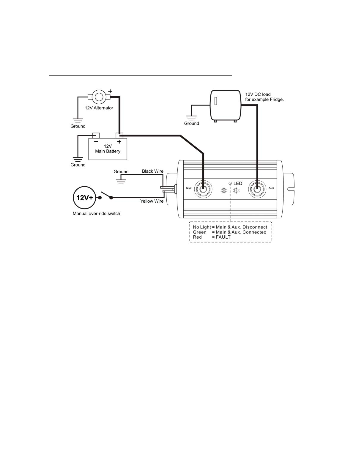
4. Make sure the yellow wire (2) is isolated and insulated if not in use.
Use a toggle switch to connect this yellow wire to the positive terminal of the
battery for manual connection of the Main and Aux terminals.
4. Installation for a Two Battery System
1. Select the suitable Disconnect (LVD) and Connect voltages (LVR) according
to your requirement. For a normal 2 battery system the LVD is about 12.4V
and LVR is about 13.3V. However the selections depend on the relative
capacity difference of the 2 batteries and load at the auxiliary battery. It is
advisable to make the difference between LVD and LVR wider if rapid on off
actions occur frequently.
2. Please note that for the unit to function properly selections of LVR is always
greater than LVD.
3. Switch off the car of DC charging source, connect the Main terminal first then
the Aux. terminal. Switch on the car or the DC charging source, if the main
battery is full and the auxiliary is low the green LED will be on.

4. If the LED turns red at any time check on the specifications and make the
necessary remedial action. There is no connection and operation when LED
turns red. Once the fault has been cleared unit will return to normal operation.
5. Installation for a One Battery System
1. The selected LVD is usually lower than the two battery system since the unit
here is mainly used as a protection against over discharging the battery.
2. However, the selection of LVD and LVR voltage are very much affected by the
type of load and relative battery capacity. Select a higher LVD for relatively
smaller load ; for high initial draw load such as Motor, choose a lower LVD.
3. It is advisable to use a higher value of LVR to ensure a more completed
charging operation .
4. Check the battery’s specifications for suitable LVR and LVD and in cycling or
standby applications.
5. If the LED turns red at any time check on the section of LED INDICATIONS of
the specifications and make the necessary remedial action. There is no
connection and operation when LED turns red. Once the fault has been
cleared unit will return to normal operation.

6. Features
1. 10 Selections of Disconnect Voltage
2. 10 Selections of Re-connect Voltage
3. MCU control with FET design resulting extremely low voltage drop & small
standby current.
4. Wide Operating Temperature Range : - 40°C to + 60°C
5. Extruded Aluminum housing sealed with Polycarbonate end caps
7. Protections
1. Instant disconnection when main terminal drops to 8.5V .
2. Over voltage protection at the main terminal.
3. Over temperature to the isolator >90°C case temperature
4. Over current to the unit .
5. Input reversed polarity protection to Main Terminal (self reset)

8. Specifications
Models MB-3680 MB-3682
Battery Voltage System 12VDC 24VDC
Isolator Setting Tolerance: ±0.1Vdc for 12Vdc
sys.
Tolerance: ±0.2Vdc for 24Vdc
sys.
LVD
(Disconnect) LVR (Connect) LVD
(Disconnect) LVR(Connect)
10.5V 12.9V 21.0V 25.8V
10 Disconnect Voltage
Selections and 10 Connect
Voltage Selections.
LVD = Cut Out = Disconnect.
LVR = Cut In = Connect
10.9V 13.0V 21.8V 26.0V
11.2V 13.1V 22.4V 26.2V
11.5V 13.2V 23.0V 26.4V
11.9V 13.3V 23.8V 26.6V
12.1V 13.4V 24.2V 26.8V
12.4V 13.5V 24.8V 27.0V
12.6V 13.6V 25.2V 27.2V
12.8V 13.7V 25.6V 27.4V
13.0V 13.8V 26.0V 27.6V
ON / OFF Delay Time For
Isolator Mode 15 Seconds
Protection
Low Voltage Protection (No
Delay) 8.5VDC ±0.5VDC 17VDC ±1.0VDC
Over Voltage Protection 18.5VDC ±0.5VDC 34.5VDC ±1.0VDC
Over Temperature Protection Yes
Protection Current (Start
Point) 150A
Continuous Output Current 100A
Maximum Output Current
(1 Minute) 110A
Operation Current
Consumption (LED ON) 9mA
Standby Current
Consumption (LED OFF) 6mA
Voltage Drop With 100A
(Main Batt. To Aux. Batt) 300mV (Max.)
Operation Temperature
Range ℃℃-40 to +60
Manual Over-ride Yellow cable (2) to Battery Positive triggers Main & Aux
connection
Indication By LED
LED GREEN = Connect LED No Light = Disconnect
LED RED Protection:
1) Solid RED = Over Voltage (OVP).
2) Slow Flash RED = Over Temperature (OTP).
3) Fast Flash RED = Over Current (OCP).
Dimension (L x W x H) 162x75x50mm (6.3x3.0x2.0 inch)
Weight 486g (17oz)

9. Dimension Diagram
This manual suits for next models
1
Table of contents
Other PowerTech Camera Accessories manuals
Popular Camera Accessories manuals by other brands

Ikelite
Ikelite Digital Housing Supplemental instructions

SLIK
SLIK PRO 780DX operating instructions

Ikelite
Ikelite Digital Housing instruction manual

Dragonfly Energy
Dragonfly Energy Battle Born Batteries BBGC3 Manual and installation guide

SLINGSTUDIO
SLINGSTUDIO Battery quick start guide

ASL INTERCOM
ASL INTERCOM BLuFisH HD user manual