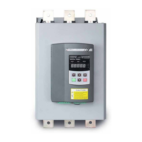
Powtran PR5300 User manual

Foreword
Thank you very much for purchasing PR5300 soft starter.
This User’s Manual provides the users with the instructions on the installation,
parameter setting, error diagnosis, remote control software instruction, routine
maintenance and necessary precautions. Please read the Manual carefully before the
installation of the product in order to ensure that it can be correctly installed and
operated.
Please contact Powtran's dealers or directly contact with the company if you have
difficult questions during the use of the soft starter , our professional staff is willing to
serve for you.
Please leave this manual to the end user and keep it in good condition for the future
maintenance and other application occasions . Please fill in the warranty card then fax to
the distributor or fax to Powtran if there is quality problem during the warranty period.
During this product updating period, some details may be changed without prior
notice. If you want to get the latest information, please visit our website.
For other products’ information, Please visit our homepage:
http://www.powtran.com
Powtran
January , 2018

Contents
Chapter 1 The introduction of PR5300 soft starter.................................................1
1-1. The feature of the PR5300 soft starter...................................................1
1-2. The main function of the PR5300 soft starter........................................1
1-3. The main features of the PR5300 soft starter ........................................1
Chapter 2 Product model description and open - package inspection...................3
2-1. Product model description.....................................................................3
2-2. The steps of open - package inspection.................................................3
Chapter 3 The conditions of use and installation requirements.............................4
3-1. The conditions of use of the soft starter.................................................4
3-2. The installation requirements of the soft starter ....................................4
3-3. The appearance and installation dimension of the soft starter ...............5
Chapter 4 Main circuit and terminal wiring............................................................9
4-1. The basic wiring diagram of the soft starter ..........................................9
4-2. Instruction of soft starter terminal wiring..............................................9
Chapter 5 Control panel and operation .................................................................12
5-1. Keyboard operational approach...........................................................12
5-2. Function parameters setting and description .......................................13
5-3. Programmable relay output functions..................................................14
5-4. The electrical terminal running protection functions...........................14
5-5. Other Settings description ...................................................................15
5-6. Help and instructions...........................................................................15
Chapter 6 Protection and description.....................................................................16
6-1. Protection functions and their parameters ...........................................16
6-2. Protection level setting description......................................................16
Chapter 7 Test runing and application...................................................................18
7-1. Power test running...............................................................................18
7-2. PR5300 Series soft starter starting mode and application....................19
7-3. PR5300 series soft starter's stop mode and application .......................20
7-4. Special application ..............................................................................21
7-5. Application examples..........................................................................21
Chapter 8 RS485 communication...........................................................................23
8-1. Summary of the modbus RTU communication protocol.....................23
8-2. The soft starter associated settings ......................................................23
8-3. Exception reponse ...............................................................................24
8-4. Using the matters need attention .........................................................25
Chapter 9 Fault causes and treatment....................................................................26
Chapter 10 Soft starting model specifications and options...................................27
Chapter 11 Warranty...............................................................................................28

3
Safety precautions
Thank you very much for purchasing PR5300 soft starter.
Under the soft starter installation, using and maintenance of process must pay attention to the
following.
Please be sure to read the instructions before installation.
the soft starter must be installed by the professional technical personnel.
The motor specification must match the soft starter.
It is prohibited to connect capacity in U.V.W terminal of soft starter
The bare terminals must be wrapped in electrical tape after installation.
Soft starter or other equipment should be grounding.
Must cut off the input power supply before maintenance.
Not allowed to rob the handling, modification and maintenance of this product.
Only the well-trained personnel can be allowed to operate this unit, please
carefully read the instructions on safety, installation, operation and
maintenance before use. The safe operation of this unit depends on proper
transport, installation, operation and maintenance!


1
Chapter 1 The introduction of PR5300 soft starter
1-1.The feature of the PR5300 soft starter
PR5300 series intelligent motor soft starter is the integration of new equipment for the new
motor control theory and specialized motor protection technology and advanced software
technology, is early for starting motor star /delta conversion and self coupling voltage, magnetron
step-down starting equipment, the ideal alternative products; its performance is currently on the
market most without the use of intelligent control technology of ordinary soft starter incomparable
starting. PR5300 series products are soft starting device for motor soft starting and on line
operation control.
1-2.The main function of the PR5300 soft starter
First: To reduce the motor starting current and reduce power distribution capacity, avoid
investment of expansion of power capacity.
The second: To reduce the starting stress of the motor and the load of the equipment ; extend
lifespan of the motor and related equipment.
Third: Its soft stop function can effectively solve the problem of parking vibration of the
inertial system,which is unable to realize by traditional starting equipment.
Fourth: To have six unique start-up modes adapts to the complex conditions of motor and
load, to perfect start effect.
Fifth: Has the perfect and reliable protection function; effectively protect the motor and the
related production equipment use safety.
Sixth: Motor soft starter intelligence, and network technology application makes motor
control technology to adapt to the rapid development of the electric power automation
technology in higher requirements.
1-3.The main features of the PR5300 soft starter
●Perfect human nature design:
Beautiful shape and reasonable structure
Perfect function and easy operation
Sturdy and reliable and compact structure
Industrial product excellence in the design of art.
●Reliable quality assurance:
Using the computer simulation design.
SMT placement production process.
Excellent electromagnetism compatibility.
The whole machine of aging, vibration test in high temperature before they leave the
factory
●Perfect and reliable protection function:
Voltage lose, lower voltage and over-voltage protection.
Soft starter motor overheating, lower load, too long starting time protection.
Input phase lose, output phase lose, three-phase unbalance protection.
Start-up current, overload, short circuit protection.
●Proprietary intellectual property products:
Appearance design patent.
Independent software copyright.

Chapter 1 The introduction of PR5300 soft starter
2
Proprietary motor starting and protection technology.
Unique testing debugging equipment and process.
●Swift thoughtful after-sales service:
Reliable performance and quality lay the foundation of excellent service.
Provide excellent perfect supporting design scheme.
Timely and thoughtful use consultation.
Continuously improve product performance according to user opinion

3
Chapter 2 Product model description and open - package
inspection
2-1.Product model description
2-1-1. Instructions on nameplate
2-1-2.Model designation
Powtran soft starter
PR 530 0 a 132 G 3
Model specification
Machine code:
a:General(omit)
C:Integrative machine
Output configuration
0:General configuration(omit)
Input Voltage Level
2:Three-phase 220V±10%
3:Three-phase 380V±10%
4:Three-phase 460V±10%
5:Three-phase 575V±10%
6:Three-phase 660V±10%
Function code
G:Gerneral
Rated Power:
Example:132: 132kW
500: 500kW
Class code:
0:normal configuration
1:special 1 configuration
2:special 2 configuration
2-2.The steps of open - package inspection
Each PR5300 series soft starter is under strict inspection and testing before they leave the
factory. Users received the products and unpacked, please follow the inspection steps , if found
problem, please contact the supplier promptly.
Confirm the soft starter without any damage in transport process (Machine body damage or
gap).
Check with the machine, the instruction manual, the warranty card
Check the product of the specifications of the enclosure panels, ensure that the received goods
match with you ordered products

4
Chapter 3 The conditions of use and installation requirements
PR5300 series soft starter should comply with the following conditions of use and installation
requirements; otherwise, the performance will not guarantee, it can shorten life of soft starter even
damage.
3-1.The conditions of use of the soft starter
3-1-1. Power supplies: The utility, self-power station, diesel generating sets three-phaseAC
380 V plus or minus 10%, frequency 50 Hz or 60 Hz, the power supply capacity must meet soft
starter motor starting to the requirement.
3-1-2. Applicable motor: Mouse cage type three-phase asynchronous motor, ac motor rated
power should be matching with soft starter rated power .
3-1-3. Start frequency: No demands, depending on the specific number load up.
3-1-4. Cooling way: Forced air cooling.
3-1-5. Protection level: Increasing non-standard parts can reach IP20.
3-1-6. Environmental conditions: Below elevation 3000 meters, the environment
Temperature between -25 ℃~+ 40℃,relative humidity below 90% RH, no dewing, no
inflammable, no explosive, no corrosive gas easily, have no electrical conductivity dust, indoor and
ventilated good, vibration is less than 0.5 G place.
3-1-7. Ambient temperature: Storage, -25 to 70 degrees Celsius; online operation, 0 to 40
degrees Celsius, the maximum to 60 degrees Celsius, 40 degrees Celsius above 1 degrees Celsius
by the current rating to reduce the use of 2% drop.
We can offer under special conditions of use products, such as the explosion proof type, low
temperature, high pressure type type soft starter, its use conditions will need further instructions.
3-2.The installation requirements of the soft starter
The installation direction and distance: In order to ensure that the soft starter in use with
good ventilation and heat dissipation conditions, the soft starter should be installed vertically, and
around the equipment left enough space for heat dissipation, as shown in Figure 3.1, Figure 3.2,
Figure 3.3, Figure 3.4the graph to allow the minimum distance.
When the soft starter cabinet installation, in addition to the above requirements, must choose
top, below ventilated cabinet.
Figure 3.1 Figure 3.2
Installation requirement for PR5300G3 11-115kW
OUT
OUT
IN IN
AIR
50mm 50mm
150mm 150mm

Chapter 3 The conditions of use and installation requirements
5
150mm
more than 150mm
more than
Air
OUT OUT
In In
150mm
more than
Figure 3.3 Figure 3.4
Installation requirement for PR5300G3 132-500kW
3-3.The appearance and installation dimension of the soft starter
PR5300 series 132kW-500kW soft starter appearance and installation dimensions are as
follows. PR5300 series 132kW-500kW soft start, its factory standard configuration for three-six.
The rated power and rated current is max rated value of soft starter. Usually, matching the
corresponding parameter of motor shall not be more than this value.
Shape and mounting dimension for PR5300G3 11-115kW:
H1
H
W
d
a
b
L

Chapter 3 The conditions of use and installation requirements
6
G2 series
Model
Rated
Power
(kW)
Rated
current
(A)
Dimension(mm)
Installation(mm)
Net (kg)
L
W
H1
H
a
b
d
PR5300 7R5G2
7.5
30
344
156
242.5
188.5
324
125
9
<7.8
PR5300 011G2
11
45
344
156
242.5
188.5
324
125
9
<7.8
PR5300 015G2
15
60
344
156
242.5
188.5
324
125
9
<7.8
PR5300 018G2
18.5
75
344
156
242.5
188.5
324
125
9
<7.8
PR5300 022G2
22
90
344
156
242.5
188.5
324
125
9
<7.8
PR5300 030G2
30
110
344
156
242.5
188.5
324
125
9
<7.8
PR5300 037G2
37
150
405
206
223
169
385
160
9
<12.8
PR5300 045G2
45
180
405
206
223
169
385
160
9
<12.8
PR5300 055G2
55
230
405
206
223
169
385
160
9
<12.8
G3 series
Model
Rated
Power
(kW)
Rated
current
(A)
Dimension(mm)
Installation(mm)
Net (kg)
L
W
H1
H
a
b
d
PR5300 011G3
11
23
344
156
242.5
188.5
324
125
9
<7.8
PR5300 015G3
15
30
344
156
242.5
188.5
324
125
9
<7.8
PR5300 018G3
18.5
37
344
156
242.5
188.5
324
125
9
<7.8
PR5300 022G3
22
45
344
156
242.5
188.5
324
125
9
<7.8
PR5300 030G3
30
60
344
156
242.5
188.5
324
125
9
<7.8
PR5300 037G3
37
75
344
156
242.5
188.5
324
125
9
<7.8
PR5300 045G3
45
90
344
156
242.5
188.5
324
125
9
<7.8
PR5300 055G3
55
110
344
156
242.5
188.5
324
125
9
<7.8
PR5300 075G3
75
150
405
206
223
169
385
160
9
<12.8
PR5300 090G3
90
180
405
206
223
169
385
160
9
<12.8
PR5300 115G3
115
230
405
206
223
169
385
160
9
<12.8
G4 series
Model
Rated
Power
(kW)
Rated
current
(A)
Dimension(mm)
Installation(mm)
Net (kg)
L
W
H1
H
a
b
d
PR5300 011G4
11
23
344
156
242.5
188.5
324
125
9
<7.8
PR5300 015G4
15
30
344
156
242.5
188.5
324
125
9
<7.8
PR5300 018G4
18.5
37
344
156
242.5
188.5
324
125
9
<7.8
PR5300 022G4
22
45
344
156
242.5
188.5
324
125
9
<7.8
PR5300 030G4
30
60
344
156
242.5
188.5
324
125
9
<7.8
PR5300 037G4
37
75
344
156
242.5
188.5
324
125
9
<7.8
PR5300 045G4
45
90
344
156
242.5
188.5
324
125
9
<7.8
PR5300 055G4
55
110
344
156
242.5
188.5
324
125
9
<7.8
PR5300 075G4
75
150
405
206
223
169
385
160
9
<12.8
PR5300 090G4
90
180
405
206
223
169
385
160
9
<12.8
PR5300 115G4
115
230
405
206
223
169
385
160
9
<12.8

Chapter 3 The conditions of use and installation requirements
7
Shape and mounting dimension for PR5300G3 132-500kW:
W
L
H
a
b
d
G2 series
Model
Rated
Power
(kW)
Rated
current
(A)
Dimension(mm)
Installation(mm)
Net
(kg)
L
W
H
a
b
d
PR5300 075G2
75
260
563
440
290
526
280
11
<40
PR5300 090G2
90
320
563
440
290
526
280
11
<40
PR5300 115G2
115
370
563
440
290
526
280
11
<40
PR5300 132G2
132
420
563
440
290
526
280
11
<40
PR5300 160G2
160
560
563
440
320
530
280
11
<49
PR5300 185G2
185
600
563
440
320
530
280
11
<49
PR5300 200G2
200
660
563
440
320
530
280
11
<49
G3 series
Model
Rated
Power
(kW)
Rated
current
(A)
Dimension(mm)
Installation(mm)
Net
(kg)
L
W
H
a
b
d
PR5300 132G3
132
260
563
440
290
526
280
11
<40
PR5300 160G3
160
320
563
440
290
526
280
11
<40
PR5300 185G3
185
370
563
440
290
526
280
11
<40
PR5300 200G3
200
400
563
440
290
526
280
11
<40
PR5300 250G3
250
500
563
440
290
526
280
11
<40
PR5300 280G3
280
560
563
440
320
530
280
11
<49
PR5300 320G3
320
630
563
440
320
530
280
11
<49
PR5300 400G3
400
800
670
500
320
640
350
11
<80
PR5300 450G3
450
900
670
500
320
640
350
11
<80
PR5300 500G3
500
998
670
500
320
640
350
11
<80

Chapter 3 The conditions of use and installation requirements
8
G4 series
Model
Rated
Power
(kW)
Rated
current
(A)
Dimension(mm)
Installation(mm)
Net
(kg)
L
W
H
a
b
d
PR5300 132G4
132
260
563
440
290
526
280
11
<40
PR5300 160G4
160
320
563
440
290
526
280
11
<40
PR5300 185G4
185
370
563
440
290
526
280
11
<40
PR5300 200G4
200
400
563
440
290
526
280
11
<40
PR5300 250G4
250
500
563
440
290
526
280
11
<40
PR5300 280G4
280
560
563
440
320
530
280
11
<49
PR5300 320G4
320
630
563
440
320
530
280
11
<49
PR5300 400G4
400
800
670
500
320
640
350
11
<80
PR5300 450G4
450
900
670
500
320
640
350
11
<80
PR5300 500G4
500
998
670
500
320
640
350
11
<80

9
Chapter 4 Main circuit and terminal wiring
PR5300 series soft starter has two kinds of wiring:
The main circuit wiring: Three phase power input and output to the motor wiring and coil in
line circuit breaker, bypass contactor wiring.
External terminal wiring: By 14 small terminals derivation, including input, output control
lines and analog output signal lines.
4-1.The basic wiring diagram of the soft starter
Braker
(QF)
Soft Starter
Squirrel cage
three-phase
asynchronous motor
RST
R S T
U V W
Figure 4- 1
4-2.Instruction of soft starter terminal wiring.
Output terminal like Figure 4.2 illustration:
12345678910 11 12
-+
Bypass
output
Programming
output
Fault
output 7.Instantaneous
stop
stop start public Analog output
13 14
Communication
terminal
485+
485-
Figure 4- 2

Chapter 4 Main circuit and terminal wiring
10
78910
Transient
stop
stop start common
3lines way
78910
Transient
stop
stop start common
2lines way:close K start
open K stop
K
Category
Terminal
name
Description of functions
Bypass output
Terminal 1
Used to control bypass contactors, for the constant opening
of passive contacts, closed when the start is successful. The
contact capacity is: AC250V/5A.
Terminal 2
Programming
output
Terminal 3
The output mode and function are set by the setting item PE
and are often open passive contacts. The contact capacity is:
AC250V/5A.
Terminal 4
Fault Output
Terminal 5
The soft starter is closed when it fails or loses power, and it
is open when it is working properly. It is an passive contact.
The contact capacity is: AC250V/5A.
Terminal 6
Halt
Terminal 7
When the soft starter is working properly, this Terminal
must be short-connected to terminal 10. If this terminal and
terminal 10 are open, the soft starter stops working
unconditionally and is in failsafe state. This terminal can be
controlled by the normally closed output point of the
external protection device. When setting item PA to
0(Primary protection), this terminal function is disabled.
STOP
Terminal 8
The terminals 8, 9, and 10 are external control start and stop
buttons input junction terminals. There are two ways to
connect, that is, 3 lines and 2 lines. Connections can be
selected as needed, as shown in Figure 4.3.
Start
Terminal 9
Common
terminal
Terminal 10
Simulated
current output
Terminal 11
Terminal 11 and 12 are 0 to 20 ma, 4 to 20 ma DC analog
output: For real-time monitoring of motor current, at a full
degree of 20 ma, indicating that the motor current is 4 times
the nominal current of the soft starter. Externally observed
with 0 to 20 ma, 4 to 20 ma DC current meters, the
maximum output load resistance is 300 Ω. (Note: The
machine defaults to 4 to 20 ma output. If 0 to 20 ma output
is required, please explain it at the time of ordering. )
Terminal 12
Communication
terminal
Terminal 13
13 is the communication terminal "485-'' and 14 is the
communication terminal" 485 + ".
Terminal 14
Control board
select jumper
J13
The fan is always running when 2-3 is short, and the fan is
running when 1-2 is short(Default).
Control board
select jumper
J12
Switching between online and bypass operations is
controlled by jumper J12, 2-3 short connections are
online(Default), and 1-2 short connections are bypass
operations.
(Note: Do not misconnect the external terminal line, otherwise it may cause damage to the
soft starter.)
Figure 4- 3
The main circuit and secondary wiring diagram of PR5300 series soft starter are shown in
Figure 4.4 below.
Soft starter terminals R, S and T are connected with three-phase power supply, and soft starter
terminals U, V and W are connected with motor.

Chapter 4 Main circuit and terminal wiring
11
Circuit
breaker
(QF)
01 02 03 04 05 06
A
-+
Analog output
(0~20mA 4~20mA)
KH/Instant
stop STOP Star Common end
485+
Communication
terminal
07 08 09 10 10 11 12 13 14 PE
R S T
S
RT
U
KH
VW
485-
Electric
machinery
PR5300 Series Soft Starter
Delayed output
By-pass output Fault output
Figure 4- 4

12
第
十
章
Chapter 5 Control panel and operation
PR5300 series soft starter has 5 kinds of working state: Preparation, operation, fault, start and
stop. Different indicate light show at preparation, operation and fault. When starting to show
XXXX, soft stop display: -XXX, XXXXX means motor current.
5-1.Keyboard operational approach
JP3E5300 keyboard diagram
Rapid select/confirm
parameter setting
Running key
Parameter setting
/shift key
Stop/reset key
Figure 5- 1
5-1-1.Start and stop key:
The role of the start key is to start keyboard, stop key has stop and reset function.
5-1-2.PRG key :
In the non-help mode, press the PRG Key to enter the setup menu,display PX: XXX,then
press PRG key again, colon flashes, that means can modify the parameters after colon.Press the Set
key when the colon flashes, if the data has been modified, it will display good and twice ring,
indicating that new data has been saved, and then exit. If you do not want to save the new data,
press the PRG key, colon will stop flashing and restoring the original data, then press Set key or
Stop key to exit.
5-1-3.Set key:
In the non-setting state, press the Set key to enter the Help menu,display HX: XXX, press the
Set key or Stop key to exit. In setting state, press the Set key to save the new setting of data and to
exit the setting state.
5-1-4.Acceleration,deceleration key:
In the setting menu, when the colon does not flash ,press the acceleration or deceleration key
to change the function number; when colon flashes, press the acceleration or deceleration key to
change the data, press on the acceleration or deceleration key for more than 1 second, the data will
be increased or decreased continuously and quickly .In the help menu, press the acceleration or
deceleration key to change the function number and the corresponding message.When the indicator
light of bypass operation is on, and did not enter the setting and help menu, display AXXXX, that
means the motor running current, then press the acceleration or deceleration key to select display
PXXXX or HXXXX.PXXXX indicates motor apparent power;HXXXX indicates motor
overloaded heat balance coefficient. When indication value of HXXXX is more than 100%,soft
starter will be overload protection and display Err08.

Chapter 5 Control panel and operation
13
5-2.Function parameters setting and description
Function parameters code in the following table
Code Setting Description
Code
Name
Range of
set value
Factory
setting
Explanation
P0
Starting voltage
30-70%
30%
Voltage slope model is effective, the
starting voltage of current mode is 40%.
P1
Soft start time
2-60S
16S
Limiting current mode is invalid.
P2
Soft stop time
0-60S
0S
Setting 0 means free stopping, please set 0
for one with two connections.
P3
Start interval delay
0-999S
0S
The minimum time between two
successive start, the function of protecting
thyristor.
P4
Select Language
0 or 1
0
0:Chinese,1:English.
P5
Starting to confine
current
50-400%
280%
Limiting current mode is effective, the
maximum current limit value of Voltage
slope model is 400%.
P6
Load Regulation
50-200%
100%
The value of PP rated current.
P7
Under voltage
protection
40-90%
80%
Protection when below the set value
P8
Over voltage
protection
100-140%
120%
Protection when higher than the set value.
P9
Start mode
0-6
1
0 Limit current,
1Voltage,
2 Sudden stop + limit current,
3 Sudden stop + voltage,
4 Current ramp,
5 Pairs of closed-loop.
6 Monitoring
PA
Level of protection
0-4
4
0 Primary,
1 Light load,
2 Standard,
3 Overloaded
4 Senior
PB
Control method
0-6
1
0 Keyboard;
1 Keyboard + external control;
2 External control;
3 External control+ communication;
4 Keyboard + external control +
communication;
5 Keyboard + communication;
6 communication.
PC
Parameters modified
allowed
0-3
1
See note 5.5 Other settings.
PD
Communication
Address
0-64
0
Used to setting MODBUS slave address
on the machine.
PE
Programming output
0-19
7
See note 5.3 programmable relay output.
PF
Soft stop the current
20-100%
80%
See note 7.3.1 soft stop mode.

Chapter 5 Control panel and operation
14
Code Setting Description
Code
Name
Range of
set value
Factory
setting
Explanation
limit
PP
Motor rated current
11-998A
Rated
value
Used to input motor nominal is rated
current.
PU
Bypass delay
0-40S
3S
Used to set the delay time of Bypass
PL
Allowed three-phase
imbalance
0 or 1
1
0:Forbid,1:Allow
PM
Current regulation rate
50-150%
100%
Used to adjust the display of current.
PN
Voltage regulation
rate
50-150%
100%
Used to adjust the display of voltage.
Note:
1.The load regulation of P6 is based on PP calculated sustainable operation of the maximum
current according to the light and heavy of the load, above this value will do inverse time thermal
protection.
2.It will automatically exit the setting mode, if no key operation is more than 2 minutes
during setting state.
3.It’s not allowed to set parameters in the soft start and soft stop process..
4.Pressing the Set key (PRG) when powered on the soft starter, can default the parameters to
factory setting.
5-3.Programmable relay output functions
There are two programmable relay output function, programmable timing output way and
programmable state output way.
5-3-1.PE set from 0 to 4 items (10 ~ 14), programmable output work is timing output way, the
setting of output starting time as tabled below:
PE setting
value
0(10)
1(11)
2(12)
3(13)
4(14)
Programming
output time
Initiate action
command
Starting at the
beginning
Bypass
operation
Stop action
command
Stopping is
complete
5-3-2.PE is from 5 to 9 (15 ~ 19), the programmable output work is state output mode, the
setting of the working state output as tabled below:
PE set value
5(15)
6(16)
7(17)
8(18)
9(19)
State of output
indication
Motor fault
conditions
Running
Preparation
state
Start state
Bypass state
(1)Programmable state output to indicate the working state of the soft starter, the time set by
P4 is invalid in this mode. The factory setting of PE is 7, which indicates the preparation state of
soft starter, can start the motor in this state; programmable output is in the failure state, which
indicates the fault of the motor (Err05, Err06, Err07, Err08, Err12, Err15), which is different from
the function of ⑤, ⑥fault output terminals; running state refers to non preparation or fault
condition, which includes 3 process of start, bypass, soft-stop.
(2)When PE> 9, the reset state of the programmable output (③, ④No. External pin) changed
from normally open to closed, that is inverted output. Flexible using the function of programmable
relay output, which can effectively simplify the external control logic circuit.
5-4.The electrical terminal running protection functions
The functions divided into two states and they can be chosen by jumper mode
State 1:The electrical terminal running protection is valid: The external control terminal is on

Chapter 5 Control panel and operation
15
closed state before power on, soft starter will not respond the command , you must cancel the
running command by one time ,then give it run command again to make the soft starter work.
When soft starter fault reset, continuous running command is valid. Soft starter will not
respond the running command, you need to removed running command and then the running
protection state is canceled.
State 2:The electrical terminal running protection is invalid: the motor will start automatically
when the external control terminal in the closed state with power on , this is to say allow power on
start.
State 1 is shorted the 2, 3 of J14; state 2 is shorted the 1, 2 of J14.
5-5.Other Settings description
PC is the selection of allowing to modify parameter, there are three options:
1) PC is set to 0, it is prohibited to modify any parameter .
2) PC is set to 1,it is prohibited to modify P4, P6, PD, PE, PP, PU parameters.
3) PC is set to 2, it is allowed to modify all the parameters.
5-6.Help and instructions
Help information as following table:
Display
Explanation
AC:XXX
Three digital voltmeter, to monitor three-phaseAC power supply voltage.
45A-380V
The specifications of soft starter is 45A/380V.
H1:E05
Last occurred fault information Err05.
H2:E01
There had been a fault information Err01.
H3:E06
There had been a fault information Err06.
H9:E00
There was no fault information.
Uer3.0
The software version of this product is Ver3.0. With the software upgrading,
version with the increase.
LXXXX
Total number of successful starting.
RUNXX
The spending time (seconds) of last soft starting (Starting successfully) .
Note: H1 ~ H9 with recursive way to storage newly happened nine fault information.
1) In the non-soft start and non-soft stop state, and did not enter the setting mode, press the
Set key, can enter into the Help menu, and then press the UP or DOWN key to select message.
In the help state, press the Set key or Stop button to exit help state..

16
第
十
章
Chapter 6 Protection and description
PR5300 series soft starter with complete protection to protect the safety of soft starter and
motor. During the application, appropriate protection parameters and level should be set based on
different situation.
6-1.Protection functions and their parameters
6-1-1.Soft starter over-temperature protection: The temperature rose to 80 ℃±5 ℃over-
temperature protection, when the temperature dropped to 55 ℃(the lowest), no over-temperature
protection.
6-1-2.Input phase lose protection delay time : <3 seconds.
6-1-3.Input phase lose protection delay time: <3 seconds.
6-1-4.Three-phase unbalance protection delay time: <3 seconds. It is based on the deviation of
all phase current greater than 50% ±10% . When the load current is lower than 30% of the nominal
rating of soft starter, the deviation will increase.
6-1-5.Over-current protection time during soft starting: Continuous 5 times greater than the
maximum operating current of the protection time set byp6 in Table 6.1.
6-1-6.Time of running overload protection: Continues 5 times greater than the load regulation
of the protection time setted by P6 in Table 6.1 .
6-1-7.The protection lag time of much too low supply voltage, when the power supply voltage
is lower than the 40% of limit, the protection time <0.5 seconds, or the protection time <3 seconds
if it is lower than the setting value.
6-1-8.The protection lag time of much too high supply voltage : When the power supply
voltage is lower than the 140% of limit, the protection time <0.5 seconds, or the protection time <3
seconds if it is higher than the setting value.
6-1-9.The protection delay time of load short-circuit : <0.1 seconds, the current is 10 times
more than soft starter nominal rated current. This protection can not replace fuse short-circuit
protection device.
6-1-10.Motor under load protection, the current range is 10% to 90% of motor rated current,
the protection action delay from 5 to 90 seconds.
These time parameters are from tested effective signal to a tripping protection instructions,
and the parameters just for reference. All the protection functions of PR5300 series soft starter can
be verified through the actual or simulation method. If it can't meet the user's requirements, special
protection device should be added to ensure safety.
6-2.Protection level setting description
6-2-1. In order to adapt to different applications, PR5300 series soft starter has five protection
level, there are 0: Primary, 1: Light load, 2: Standard load, 3:Heavy load, 4: Advanced, it set by PA
parameter. Among them:
1) Primary protection is against to the function of external terminal instantaneous stop,
meanwhile only remains the overheating, short circuit and main circuit fault protection, it can
be applied to needed emergency start in unconditional occasion, such as fire systems, etc.
2) The three protection level of light load, standard load and overload have the complete
protection function. The difference is the time curves of motor overloaded thermal protection
are not the same. The time parameters of motor thermal protection are as Table 6.1 and Figure
6.1. 3) High level of protection standards is stringent at start. Other protection features
parameters keep the same with standard protection set.
6-2-2. Protection level and thermal protection time according to PA setting is as the diagram
below:
This manual suits for next models
22
Table of contents
Other Powtran Controllers manuals