PPM ViaLiteHD Blue2 Link User manual


VIALITEHD-BLUE2-LINK-HANDBOOK-HRX-XX-8X-35-XXXXX
2
Instrument Care and Safety Information
Please read the whole of this section before using your ViaLiteHD product. It contains important
safety information and will enable you to get the most out of your Fibre Optic Link.
Electrical Safety
The ViaLiteHD chassis is a Safety Class 1 product (having metal case directly
connected to earth via the power supply cable).
When operating the equipment note the following precautions:
Hazardous voltages exist within the equipment. There are no user serviceable
parts inside; the covers should only be removed by a qualified technician.
There are no user replaceable fuses in the chassis mounted equipment.
Replacement should only be carried out by a ViaLite Communications
technician.
The chassis earth stud SHOULD be connected to the safety earth.
When using a 2 pin power supply cable the chassis earth stud MUST be
connected to the safety earth.
The ViaLiteHD Power Supply Modules do not have an isolating switch on the
mains voltage inlet. For this reason, the ViaLiteHD Chassis must be installed
within easy reach of a clearly labelled dual pole mains isolation switch, which
supplies the equipment.
ESD Precautions
The ViaLiteHD RF Fibre Optic Link is equipped with high frequency active
electronics, without the correct handing they will be susceptible to damage.
Precautions for handling electro-static sensitive devices should be observed
when handling all ViaLiteHD modules.
Technicians should ensure that they use effective personal grounding (i.e.
ESD wrist strap etc.) when servicing the equipment.
Any equipment or tools used should be grounded to prevent static charge
build-up.
Good practice should be observed at all times for reference see relevant
standards. EN 61340-5-1, “Protection of Electronic Devices from Electrostatic
Phenomena –General Requirements”
Optical Safety
The ViaLiteHD RF Fibre Optic Transmitters contain optical sources (usually laser
diodes) operating at nominal wavelengths of 1270nm to 1610nm.
These devices are rated as EN60825-1:2007 as CLASS 1 radiation emitting
devices. A class 1 laser is safe under all conditions of normal use.
When operating the equipment note the following precautions:
Never look into the end of an optical fibre directly or by reflection either with
the naked eye or through an optical instrument.
Never leave equipment with radiating bare fibres –always cap the connectors.
Do not remove equipment external covers when operating.

VIALITEHD-BLUE2-LINK-HANDBOOK-HRX-XX-8X-35-XXXXX
3
TABLE OF CONTENTS
1INTRODUCTION.............................................................................................................................5
1.1.1 HRX-L1-8P-33-S1310.................................................................................................................. 5
1.1.2 HRU-G1-8P-10-S1310................................................................................................................. 5
1.1.3 HRU-L3-8P-35-W1310-1550....................................................................................................... 5
1.1.4 HRV-L3-8P-03 ............................................................................................................................. 5
1.2 Blue2 Link............................................................................................................................................... 5
1.3 Typical deployment ................................................................................................................................ 5
1.4 Care of fibre optic connectors................................................................................................................ 6
2SETTING UP AND UNDERSTANDING THE FIBRE OPTIC LINK.................................................7
2.1.1 RF connectors.............................................................................................................................. 7
2.1.2 Blue2 Link Module ....................................................................................................................... 7
2.2 Fibre optic cable & connectors............................................................................................................... 9
2.2.1 Connecting and disconnecting..................................................................................................... 9
2.2.2 Cleaning optical connectors, cleaning before every use ............................................................. 9
2.2.3 Cleaning optical connectors, high levels of contamination.......................................................... 9
2.2.4 FC/APC Connectors .................................................................................................................. 10
2.2.5 SC/APC Connectors.................................................................................................................. 11
2.2.6 E2000/APC Connectors............................................................................................................. 11
2.2.7 Minimum bend radius................................................................................................................. 11
2.3 Using the RF link module..................................................................................................................... 12
2.3.1 Connecting the module.............................................................................................................. 12
2.3.2 LED indicator, purple modules................................................................................................... 12
2.4 Module Interface ratings....................................................................................................................... 12
2.4.1 Susceptibility to DC pulses from ViaLiteHD receivers............................................................... 12
2.4.2 Protection of ViaLiteHD equipment from DC pulses.................................................................. 12
2.4.3 Logic interface, TTL 5V.............................................................................................................. 12
2.4.4 Logic interface, I2C.................................................................................................................... 13
2.4.5 Logic interface, Open Drain, output........................................................................................... 13
2.4.6 Power interface, +12V, input...................................................................................................... 13
2.4.7 Analogue interface, laser diode bias, output ............................................................................. 13
2.4.8 Analogue interface, photodiode received light level, output...................................................... 13
2.4.9 RF connectors............................................................................................................................ 14
2.4.10Optical connections.................................................................................................................... 14
2.4.11Blue2 Link OEM module Connector .......................................................................................... 15
3SYSTEM INTEGRATION..............................................................................................................18
3.1 Link loss budget calculations ............................................................................................................... 18
3.2 Optical loss versus gain ....................................................................................................................... 18
3.3 Optical loss versus noise figure ........................................................................................................... 18
3.4 Gain versus frequency response ......................................................................................................... 19
3.5 P1dB versus transmitter gain............................................................................................................... 20
3.6 P1dB versus receiver gain ................................................................................................................... 22
3.7 P1dB, key observations ....................................................................................................................... 24
3.8 Noise figure versus transmitter gain .................................................................................................... 24
3.9 Noise figure versus receiver gain......................................................................................................... 25
3.10 Noise figure, key observations............................................................................................................. 25
3.11 Link IP3 ................................................................................................................................................ 25
3.12 Spurious free dynamic range............................................................................................................... 26
3.13 Phase noise ......................................................................................................................................... 26
3.14 Link delay............................................................................................................................................. 29
3.15 Group delay.......................................................................................................................................... 29
3.16 Effects of temperature.......................................................................................................................... 30
3.16.1Effect of temperature on gain .................................................................................................... 30
3.16.2Effect of temperature on noise figure......................................................................................... 32
3.16.3Effect of temperature on P1dB .................................................................................................. 32

VIALITEHD-BLUE2-LINK-HANDBOOK-HRX-XX-8X-35-XXXXX
4
3.17 RF isolation .......................................................................................................................................... 33
3.17.1RF isolation, Blue link and Yellow link cards mounted in other ViaLite enclosures .................. 33
3.18 2nd Harmonic rejection.......................................................................................................................... 34
3.19 Typical system configuration with fixed gain modules......................................................................... 35
3.20 Commissioning of a communications link............................................................................................ 35
4PART NUMBERING......................................................................................................................37
4.1 Part numbering matrix.......................................................................................................................... 37
5MAINTENANCE AND FAULT FINDING GUIDE...........................................................................38
6FCC APPROVAL...........................................................................................................................39
7PRODUCT WARRANTY...............................................................................................................40

VIALITEHD-BLUE2-LINK-HANDBOOK-HRX-XX-8X-35-XXXXX
5
1 Introduction
The ViaLiteHD RF Fibre Optic Links (FOLs) are a family of fibre optically coupled link systems
designed for the transmission of RF analogue signals over long distances for the communications
market. ViaLiteHD is a product brand manufactured by Pulse Power and Measurement Ltd (PPM).
ViaLite Communications is a division of Pulse Power and Measurement Ltd (PPM).
This handbook covers the following ViaLiteHD RF Link part numbers:
1.1.1 HRX-L1-8P-33-S1310
L-Band HTS (700-2450 MHz) Transceiver with 50 ohm SMA and SC/APC connectors
1.1.2 HRU-G1-8P-10-S1310
GPS Dual Transmitter, 50 ohm SMA, internal antenna PSU and SC/APC connectors
1.1.3 HRU-L3-8P-35-W1310-1550
L-Band HTS (700-2450 MHz) Dual Transmitter with WDM, 75 ohm F-type and SC/APC connectors
1.1.4 HRV-L3-8P-03
L-Band HTS (700-2450 MHz) Dual Receiver with 75 ohm F-type and SC/APC connectors
For complete information and product familiarisation, this handbook should be read in conjunction
with all other relevant handbooks for your ViaLiteHD system.
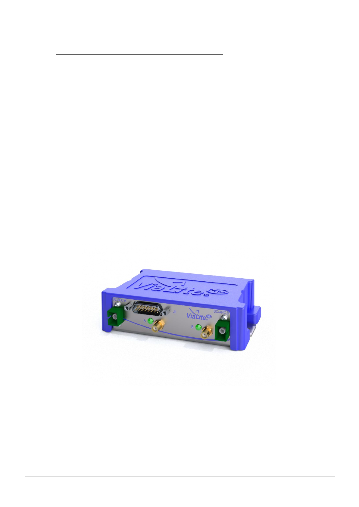
1.2 Blue2 Link
ViaLite‘s RF over fibre Blue2 Link is a dual-solution OEM which can be setup as 2x transmitters,
2x receivers or a transceiver, as required. The link is available in all ViaLite frequency bands
from 2 kHz-4.2 GHz, including ViaLite‘s extended L-Band HTS.(see the relevant characterisation
data in section 3).
1.3 Typical deployment
A typical system operates as follows.
The new Blue2 Link s a small dustproof module available in all ViaLiteHD RF bands. It can be
either a dual transmitter, dual receiver or a transceiver.
The link is available with two optical inputs/outputs or single optical input/output if the integral
WDM module option is selected.
The 15 way D-type connector is used for serial data transmission (RS232, RS485 & TTL), Tx or
Rx Alarms, I2C set up using the ViaLiteHDProgramming Kit (HRxHD-DEV103) and for
connecting an external power supply (optional HPS-CS-4).
Applications include:
Martitme
Satcom
Broadcast
GPS

VIALITEHD-BLUE2-LINK-HANDBOOK-HRX-XX-8X-35-XXXXX
6
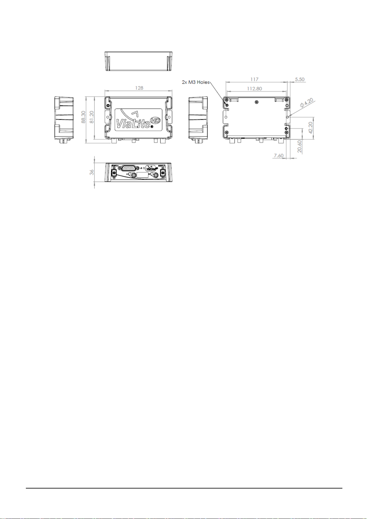
The Blue2’s compact design means it can be used in existing customer equipment or easily fitted
in smaller spaces, such as ship radomes/below-deck control rooms where space can be
restricted. In addition to maritime, the Blue2 Link is suitable for use in the Broadcast, GPS or
regular Satcom markets.
1.4 Care of fibre optic connectors
When the fibre optic cables are not connected, it is essential that the cable and equipment connectors
are protected by the dust caps provided with the system. Failure to do so may result in damage to the
fibre ends, which are critical to the system performance. Please refer to section 0 for fibre optic cable
handling details.
VIALITEHD-BLUE2-LINK-HANDBOOK-HRX-XX-8X-35-XXXXX
7
2 Setting up and understanding the fibre optic link
This section describes the connections between your RF fibre optic transmitter (electrical –optical
converter) and receiver (optical - electrical converter) modules, and the operation of both modules in a
system.
Please read fully all relevant documents for information on installing your ViaLiteHD equipment
before commissioning your RF fibre optic link system.
2.1.1 RF connectors
ViaLiteHD Blue2 Link is fitted with 50 Ohm female SMA connectors.
The SMA connector is a semi-precision sub-miniature RF and microwave connector and to maintain
performance up to 8GHz, ensure that when not in use, the supplied RF connector dust caps are fitted.
If any dust or dirt is visible within the connector body, cleaning with compressed air before mating is
advised.
When attaching cables to these RF connectors, a torque wrench should be used to guarantee
tightening to 1.0 Nm.
2.1.2 Blue2 Link Module
The Blue2 Link is an RF over fibre module available for both the transmitter and receiver. The 15-way
D-type connector provides connectivity for the Tx or Rx alarms, I2C setup using the ViaLiteHD
Programming Kit(HRx-HD-DEV103).
VIALITEHD-BLUE2-LINK-HANDBOOK-HRX-XX-8X-35-XXXXX
8

VIALITEHD-BLUE2-LINK-HANDBOOK-HRX-XX-8X-35-XXXXX
9
2.2 Fibre optic cable & connectors
All ViaLiteHD RF modules use single-mode (9µm/125µm) cable terminated in a range of optical
connectors detailed below. Cross-site fibre optic cables are available from ViaLite Communications
as either standard patch leads or heavy-duty multicore cables.
Warning!
Angle polished (APC) and standard (PC) connector must not be confused.
The two connector types are not interchangeable and mating one with the other will
damage both the cable and the module connectors.
The specification of optical connector is critical to the performance of the complete fibre
optic link. System performance can only be guaranteed with fibre optic cables and
connectors supplied by ViaLite Communications.
When FC/APC connectors are specified they must be “narrow key width”
2.2.1 Connecting and disconnecting
Before connecting optical fibres to the module or to each other, ensure that the mating connectors are
clean (see below).
2.2.2 Cleaning optical connectors, cleaning before every use
Optical connectors MUST be cleaned before use, even where they have been protected with dust
caps.
A large percentage of performance issues can be attributed to dirty fibres.
For more details please read the cleaning instruction which accompanies the connector cleaning kit.
Details can also be found on the CD supplied with your equipment.
2.2.3 Cleaning optical connectors, high levels of contamination
If there are performance issues that are not resolved by basic cleaning, then the following procedure
should be used. If the level of contamination is high it will be necessary to repeat this procedure.
Cleaning items required
Lint free fibre cleaning tissues and/or cleaning sticks (normal cosmetic tissues produce dust and
are not acceptable).
Reagent grade Isopropyl Alcohol (IPA).
Air duster or filtered compressed air line.
Cable Connector Cleaning
Dampen a patch of cleaning tissue with IPA and clean all surfaces of the plug ferrule.
Peel the plastic cover from an unused ‘N’
cleaning pad.
Hold the connector between your thumb
and forefinger
Clean the connector using firm pressure by
swiping in a pendulum motion through each
segment of the ‘N’shape, following the
diagram
Do not swipe over the same space twice.

VIALITEHD-BLUE2-LINK-HANDBOOK-HRX-XX-8X-35-XXXXX
10
Using a dry cleaning tissue, dry the ferrule and clean the end face.
Using the air duster, blow away any residue from the end of the connector.
Module Female Receptacle Cleaning (only recommended if problems are being experienced)
Either use an optical cleaning stick or twist a cleaning tissue to form a stiff probe, moisten either
with IPA. Gently push the probe into the receptacle and twist around several times to dislodge
any dirt.
Repeat the above process with a dry tissue.
Using the air duster, blow away any residue from the receptacle.
Important Notes
IPA is flammable. Follow appropriate precautions / local guidelines when handling and storing.
IPA can be harmful if spilt on skin. Use appropriate protection when handling.
It should only be necessary to clean the female receptacles on the modules if problems are being
experienced.
Warning!
Never inspect an optical fibre or connector with the naked eye or an instrument
unless you are convinced that there is no optical radiation being emitted by the
fibre. Remove all power sources to all modules, and completely disconnect the
optical fibres.
2.2.4 FC/APC Connectors
To connect FC/APC optical connectors follow these steps:
Remove the dust caps and align the white ceramic centre ferrule on the cable connector with the
mating receptacle.
There is a key (lug) on the side of the ferrule, which must match the keyway (gap) in the receptacle
shroud.
When they are aligned, gently push the plug home.
Finger tighten the knurled collet nut onto the threaded receptacle.
To disconnect follow these steps:
Using fingers fully unscrew the knurled collet nut, gently withdraw the connector.
Replace the dust caps on both the receptacle and the cable plug.
Warning!
It is possible to tighten the knurled collet without aligning the lug and gap. This
will result in poor light transmission. Check that the lug and gap are aligned
before tightening the knurled collet

VIALITEHD-BLUE2-LINK-HANDBOOK-HRX-XX-8X-35-XXXXX
11
2.2.5 SC/APC Connectors
To connect SC/APC optical connectors follow these steps:
Remove the plug protective cover.
Align the connector keyway slot in the adaptor to the key of the plug.
Gently push the plug-into the adapter until a click is heard and the connector locks.
To disconnect follow these steps:
Grip the body of the plug and gently pull the plug from the adaptor, replace the protective cover.
Only connect SC/APC cable to SC/APC receptacles.
2.2.6 E2000/APC Connectors
All ViaLiteHD E2000 connectorised modules use E2000/APC. Clean the plug before inserting.
To connect E2000/APC optical connectors:-
Gently push the plug-into the E2000/APC adapter.
The cover will automatically disengage.
Push until a click is heard and the connector locks.
To disconnect:-
To disconnect, depress the lever at the rear of the connector and withdraw the connector.
The protective cover automatically engages when removed.
Only connect E2000/APC cable to E2000/APC adaptors.
2.2.7 Minimum bend radius
Because optical fibre is made of glass, it is important not to subject it to excessive stress. For this
reason, each type of cable has a minimum bend radius (MBR) specification, beyond which the cable
cannot be bent without permanent damage occurring. Systems using longer wavelength (i.e.
1550nm) are less tolerant to small bend radii.
The minimum bend radius of standard SMF28 fibre optic cable fitted to ViaLiteHD modules is 50mm.
MBR specifications for ViaLite Communications supplied fibre optic cables are given in the ViaLite
Classic and ViaLiteHD System Handbooks Lxx-HB and Hxx-HB respectively.
VIALITEHD-BLUE2-LINK-HANDBOOK-HRX-XX-8X-35-XXXXX
12
2.3 Using the RF link module
2.3.1 Connecting the module
Connect the transmitter module to the power source, cross-site fibre optic cable and RF signals. The
RF input signal applied to the signal connector should be within the maximum and minimum signal
levels given in the datasheet.
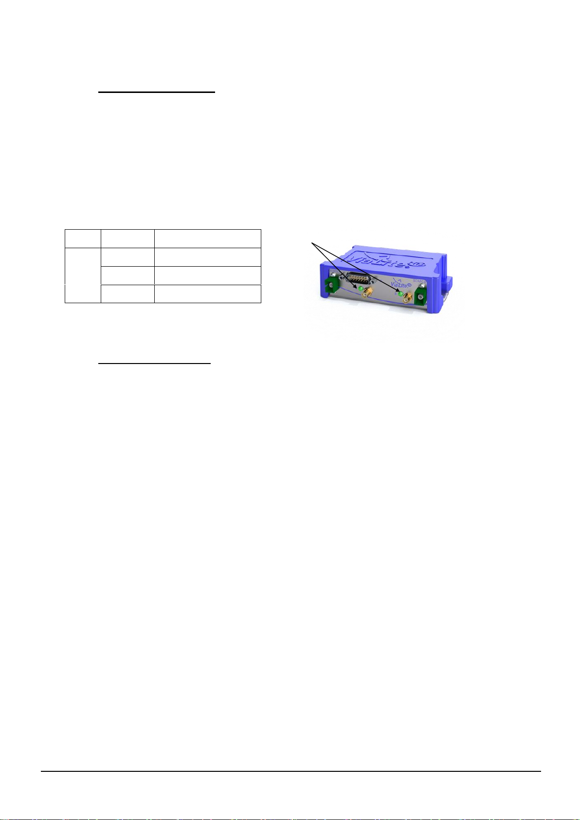
2.3.2 LED indicator, purple modules
These modules are fitted with a single LED for indication of the state of the module.
2.4 Module Interface ratings
2.4.1 Susceptibility to DC pulses from ViaLiteHD receivers
All receiver modules will create a 1-2Vpeak DC transient from the RF output at start up into a 50Ω
load (approximately 5V into a 1MΩ load). This may cause failure in some very sensitive spectrum
analysers or similar equipment. Please check before connecting your equipment. Contact ViaLite
Communications for more details.
2.4.2 Protection of ViaLiteHD equipment from DC pulses
All modules have AC coupled inputs and/or outputs and will be sensitive to large transients (>5V)
applied at the RF connector. This may result in permanent damage to the modules, particularly to low
frequency or wideband modules. DVB-T and L-Band HTS modules are designed to survive non
repetitive DC pulse of up to 36V. To increase protection, BUC feed option “B” can be specified for
GPS receiver modules to increases their robustness to DC pulses contact ViaLite Communications
for more details.
2.4.3 Logic interface, TTL 5V
Absolute maximum voltage rating -0.5 to +5.5V No damage
Input, Logic Low (max) <0.8V
Input, Logic High (min) >2.0V
Output, Logic Low (max) <0.4V no load
Output, Logic High (min) >4.8V no load
Drive capability 1k ohms
Short circuit protection No
Colour
Blue link
LED
GREEN
Normal
RED
Alarm
No Light
No power
LED

VIALITEHD-BLUE2-LINK-HANDBOOK-HRX-XX-8X-35-XXXXX
13
2.4.4 Logic interface, I2C
Absolute maximum voltage rating -0.3 to +5.3V No damage
Input, Logic Low (max) <1.5V
Input, Logic High (min) >3.5V
Output, Logic Low (max) <0.6V no load
Output, Logic High (min) >4.3V no load
Drive capability 1k ohms
Short circuit protection No
2.4.5 Logic interface, Open Drain, output
For details of operation see 2.4.3
Operational pull up voltage 0 to 15V No damage
Maximum load current 50mA
Short circuit protection No
Note: Negative voltage on the output will be clamped by the FET body diode; you must ensure that
these do not exceed current rating.
Note: When fitted in a chassis with a controller card (i.e. SNMP and web controller or summary
alarm card) the alarm lines maybe loaded and pulled up, see chassis handbook
Note: When fitted in a chassis or enclosure adjacent to a RF switch or RF splitter card, alarm lines
maybe loaded and pulled up, see chassis handbook
2.4.6 Power interface, +12V, input
Nominal input voltage 12V
Maximum operational voltage range 11.5 to 13V
Purple OEM Module include two options for the external power interface, either by the standard 15
way D connection OR via a dedicated 2.5mm concentric / barrel power port, centre positive. These
two interfaces are internal diode or to prevent power being back driven.
2.4.7 Analogue interface, laser diode bias, output
For details of operation see 2.4.7
Typical output voltage 1.25V for 50mA bias current
Typical output voltage range 0 to 2.5V
Maximum output voltage range -5 to +5V
Short circuit protection No
2.4.8 Analogue interface, photodiode received light level, output
For details of operation see 2.4.8
Typical output voltage 4.0V at 10 dBm optical input power
Typical output voltage range 1 to 4V

VIALITEHD-BLUE2-LINK-HANDBOOK-HRX-XX-8X-35-XXXXX
14
Maximum output voltage range 0 to +5V
Short circuit protection No
2.4.9 RF connectors
Maximum RF input power, no damage +13 dBm continuous, 25 dBm (5 min max)
Maximum usable input power Gain Setting Dependent (+1 dBm to -15 dBm typ)
Maximum RF output power +15 dBm typ
2.4.10 Optical connections
Maximum optical input power, no damage +16 dBm
Maximum usable input power +10 dBm
Optical output power +10 dBm typical for 10mW Transmitter
VIALITEHD-BLUE2-LINK-HANDBOOK-HRX-XX-8X-35-XXXXX
15
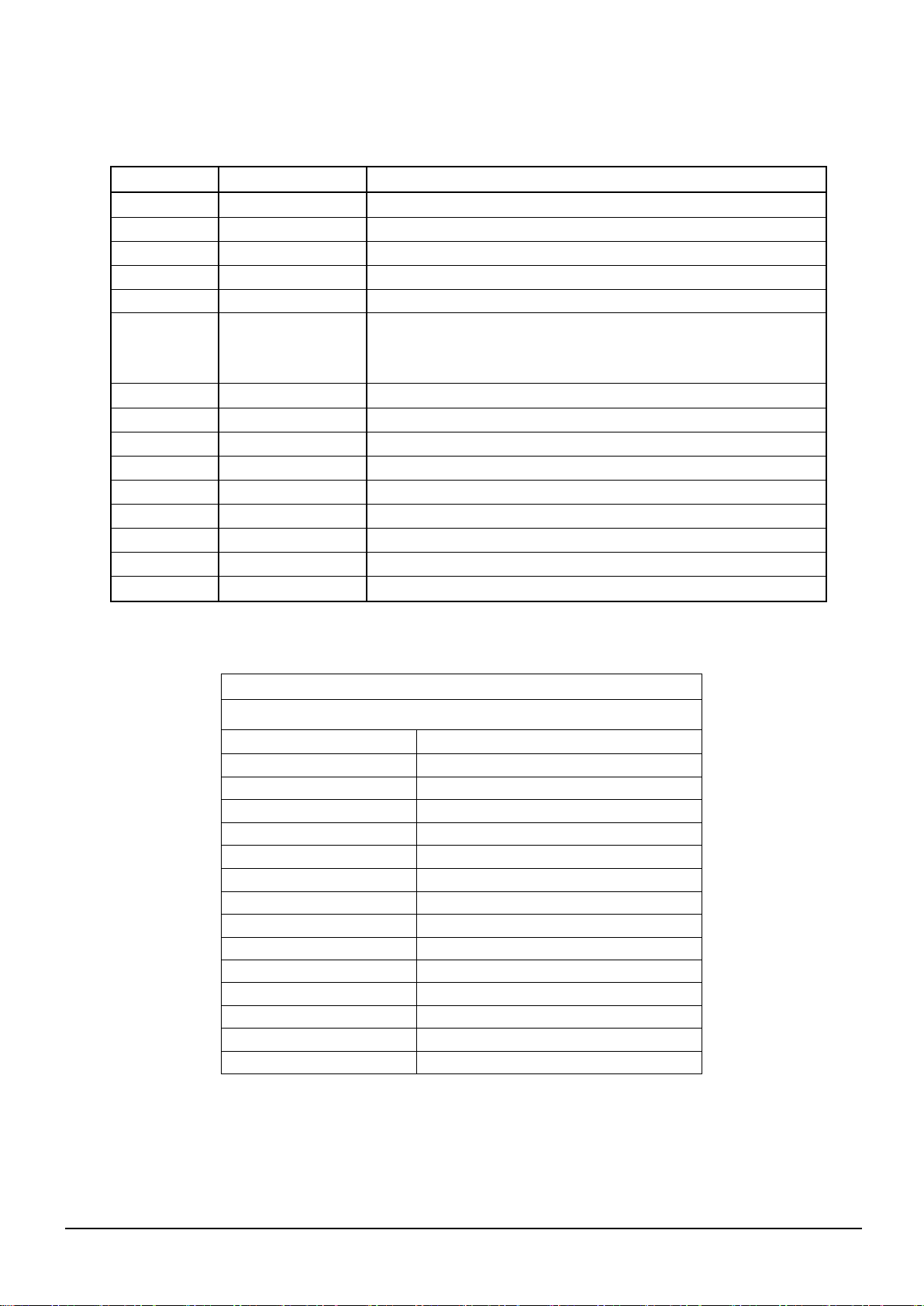
2.4.11 Blue2 Link OEM module Connector
Pin Number
Signal Name
Description
1
12V_IN
12 Volt input, 11.5V to 13V nominal, 2A rated
2
TX/RX Alarm
Alarm output from TX and RX modules
3
LD_MON
Receive Light Level monitor
4
SDA
I2C Data connection
5
SCL
I2C Clock input from master device
6
LNA_FEED
Option for external LNA feed input on Optical TX module. Only
used if Internal feed is not specified
7
No Connect
8
No Connect
9
No Connect
10
No Connect
11
No Connect
12
Ground
Ground connection
13
No Connect
14
No Connect
15
No Connect
Blue2Link - Loom - P - 2RF -Dual TX (c/w I2C & 232)
73930
15 way –D type
P1
+12V
P2
TX_ALARM (A)
P3
LD_MON (A)
P4
SDA (A)
P5
SCL (A)
P6
LNA_FEED (A)
P7
TX_232_IN (A)
P8
TX_232_IN (B)
P9
LD_MON (B)
P10
NC
P11
SCL (B)
P12
GROUND (0V)
P13
SDA (B)
P14
LNA_FEED (B)
P15
TX_ALARM (B)
VIALITEHD-BLUE2-LINK-HANDBOOK-HRX-XX-8X-35-XXXXX
16
Blue2Link - Loom - P - 2RF Dual RX (c/w I2C & 232)
73931
15 way –D type
P1
+12V
P2
RX_ALARM (A)
P3
RX_RF_MON (A)
P4
SDA (A)
P5
SCL (A)
P6
LNA_FEED (A)
P7
RX_232_OUT (A)
P8
RX_232_OUT (B)
P9
RX_RF_MON (B)
P10
Pin 10 - NC
P11
SCL (B)
P12
GROUND (0V)
P13
SDA (B)
P14
LNA_FEED(B)
P15
RX_ALARM (B)
Blue2Link - Loom - P - 2RF TRX (c/w I2C & 232)
73932
15 way –D type
P1
+12V
P2
TX_ALARM (A)
P3
LD_MON (A)
P4
SDA (A)
P5
SCL (A)
P6
LNA_FEED (A)
P7
TX_232_IN (A)
P8
RX_232_OUT (B)
P9
BUC_FEED (B)
P10
NC
P11
SCL (B)
P12
GROUND (0V)
P13
SDA(B)
P14
RLL_MON (B)
P15
RX_ALARM (B)

VIALITEHD-BLUE2-LINK-HANDBOOK-HRX-XX-8X-35-XXXXX
17
Blue2Link - Loom - P - 2RF TRX-RS485/422/232 (No I2C)
15 way –D type
+12V
TX_ALARM (A)
LD_MON (A)
422 IN+ (A)
422 IN- (A)
LNA_FEED (A)
TX_232_IN (A)
RX_232_OUT (B)
BUC_FEED (B)
RTS(485)
485/422 OUT - (B)
GROUND (0)
485/422 OUT+ (B)
RLL_MON (B)
RX_ALARM (B)

VIALITEHD-BLUE2-LINK-HANDBOOK-HRX-XX-8X-35-XXXXX
18
3 System integration
3.1 Link loss budget calculations
The link gain (transmitter RF input level to receiver RF output level) depends on the following factors:
Optical loss (due to connector insertion loss and optical fibre loss).
Transmitter gain setting.
Receiver gain setting.
The actual link gain can be determined as follows:
Link gain = Transmitter Gain + Receiver Gain –(2 x optical loss) [dB]
(Where optical loss = connector insertion losses + fibre losses)
3.2 Optical loss versus gain
The additional electrical insertion loss in dB resulting from optical losses is equal to 2 times that of the
optical loss in dB. This is due to the physics of the optical-to-electrical conversion process in the
receiver. For example, a 1dB increase in optical insertion loss will result in a 2dB decrease in RF
signal at the output of the optical receiver.
For single-mode fibre (e.g. SMF28), the optical loss at the 1310nm operating wavelength of the
ViaLiteHD link is 0.4dB/km. For 1550nm operating wavelength, the optical loss is 0.2dB/km.
This can increase if the fibre is under excessive tension, compression or is bent into a small radius.
For clean, undamaged single-mode connectors, optical insertion loss is typically 0.2dB per interface.
Note: The losses at the optical connections of the transmitter and receiver are allowed for during
manufacture of the module, and may be ignored during link gain calculations.
For short links (<250m) containing no additional optical connectors, and in which the fibre is not
subject to any strain, the optical path loss can be ignored.
3.3 Optical loss versus noise figure
As the optical loss increases there will be a corresponding increase in noise, the chart below shows
the approximate relationship of optical loss to noise figure increase for a standard L-Band HTS link.
Below are graphs that shows the change in noise figure of some popular link types.
Note: If you operate the ViaLiteHD modules in RLL AGC mode it is possible to mask optical loss
variations, but this is not always desirable.
0
5
10
15
20
25
30
35
0 2 4 6 8 10 12 14 16 18 20
Noise Figure Increase (dB)
Optical link loss (dB)
Noise Figure increase vs Optical link loss
5km @1310nm
10km @1550nm
15km @1310nm
30km @1550nm
25km @1310nm
50km @1550nm
35km @1310nm
70km @1550nm
VIALITEHD-BLUE2-LINK-HANDBOOK-HRX-XX-8X-35-XXXXX
19
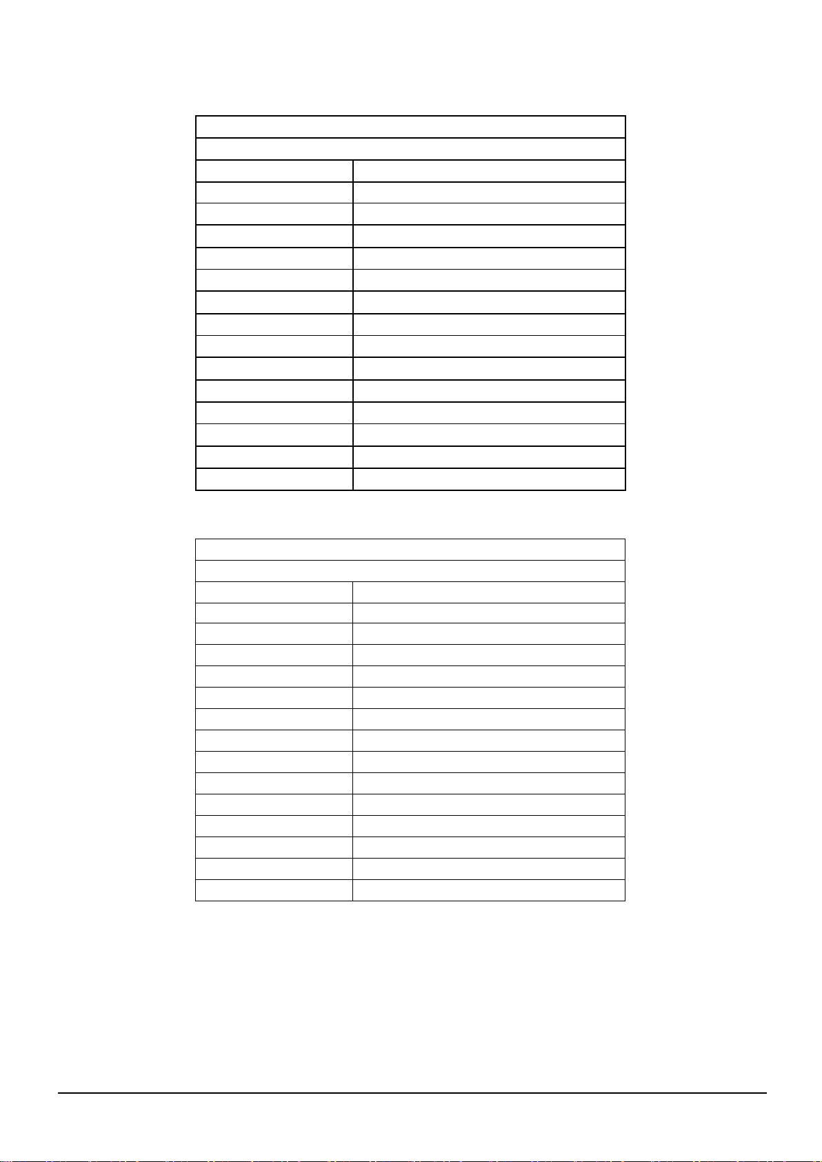
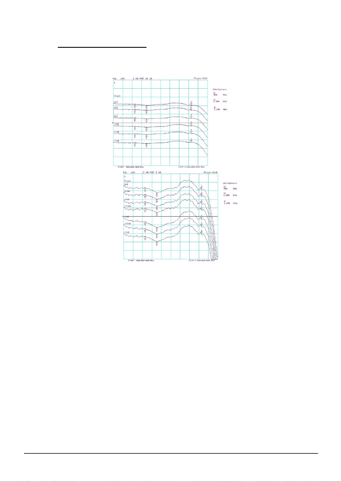
3.4 Gain versus frequency response
The frequency response is not significantly affected by the gain setting of the attenuators used in
ViaLiteHD. These have a flat frequency response over the full operating range of the product.
Figures below are typical L-Band HTS modules responses.
Gain plots versus TX gain (3dB steps) at RX gain 20dB Gain plots versus TX gain (0.5dB
steps) at RX gain 20dB

VIALITEHD-BLUE2-LINK-HANDBOOK-HRX-XX-8X-35-XXXXX
20
Gain plots versus RX gain (3dB steps) at TX gain -11dB Gain plots versus RX gain (0.5dB
steps) at TX gain -11dB
3.5 P1dB versus transmitter gain
The input P1dB of the link is dependent on the transmitter gain. Increasing the transmitter gain will
decrease the link input P1dB..
L band Input P1dB versus Tx gain at Rx gain 20dB
Input P1dB versus TX gain setting (950/1200/1700/2150MHz)
-16
-14
-12
-10
-8
-6
-4
-2
0
2
4
-20 -18 -16 -14 -12 -10 -8 -6 -4 -2 0
TXgain setting (dB)
P1dB input (dBm)
950MHz
1200MHz
1700MHz
2150MHz
This manual suits for next models
5
Table of contents


