PRÜFTECHNIK Rotalign Touch User manual

Table of Contents
ROTALIGN touch computer 2
sensALIGN laser 4
sensALIGN sensor 6
Mounting components 10
Dimensions screen 12
Initializing sensor 14
Laser beam adjustment 15
XY View 16
Measurement modes 19
Multipoint measurement 21
Live Move screen 23
Soft foot 25
Glossary 27
FictionSoft 1
(Undefined variable: General.UserGuideTitle)

ROTALIGN touch computer
ROTALIGN touch computer has a multi-touch screen and is operated by tapping and swiping. The
computer is turned on by pressing and holding down the On/Off switch at the front of the computer
until it beeps.
The computer is turned off by tapping the On/Off icon [ ] appearing in the home screen.
Computer interfaces, built-in camera, and labelling
ROTALIGN touch computer has three interfaces housed under the sliding dust cap located at the top
of the computer.
2 Edition: (Undefined variable: General.Edition)
(Undefined variable: General.UserGuideTitle)

ROTALIGN touch computer has a built-in camera at the back of the unit which may be used to cap-
ture machine images.
FictionSoft 3
(Undefined variable: General.UserGuideTitle)

sensALIGN laser
The semiconductor laser diode emits a ray of red light (wavelength 635 nm) which is vis-
ible where it strikes a surface. The Class 2 laser beam is emitted with a diameter of approx.
5 mm (3/16”).
sensALIGN laser is turned on by pressing and holding the On/Off switch briefly. The
“beam active” LED lights red.
With sensALIGN laser on, DO NOT stare into the laser beam!
The beam is adjusted during set-up by changing its vertical and horizontal angles using the position
thumbwheels, so that the beam strikes the sensALIGN sensor lens perpendicular to the lens surface.
sensALIGN laser is water and dust resistant (IP 65). The internal optics and electronics are internally
sealed, preventing possible contamination.
4 Edition: (Undefined variable: General.Edition)
(Undefined variable: General.UserGuideTitle)

Information regarding the battery status, the rotational angle, the temperature and the serial number of
the sensALIGN laser are transmitted through the laser beam into sensALIGN sensor. This inform-
ation is further relayed to ROTALIGN touch computer.
sensALIGN laser is powered using sensALIGN rechargeable battery (3.7 V 1.6 Ah Lithium Polymer
rechargeable battery). The rechargeable battery is attached to the laser and is to be charged only using
the sensALIGN charger/adapter , and is possible only when the battery is attached to the laser.
FictionSoft 5
(Undefined variable: General.UserGuideTitle)

sensALIGN sensor
sensALIGN sensor contains two position detectors, which measure the exact position and inclination
of the laser beam as the shafts are rotated. Integrated in the sensor is Bluetooth technology for wireless
transmission of measurement data to ROTALIGN touch computer. sensALIGN sensor also transmits
sensALIGN laser data to the computer. The intelligent sensALIGN sensor technology is used to
determine shaft rotational angle and machine vibration.
Positioned at the front of sensALIGN sensor are following indicator LEDs:
›› Battery status LED
›› Bluetooth communication LED
›› Four beam adjustment LEDs
Understanding the beam adjustment LEDs
6 Edition: (Undefined variable: General.Edition)
(Undefined variable: General.UserGuideTitle)

The four beam adjustment LEDs provide additional help when adjusting the laser beam position on
sensALIGN sensor position detectors. The LEDs indicate the angle and position at which the laser
beam enters the sensor. The LEDs blink either red or green depending on the angle at which the laser
beam strikes the sensor. Green indicates a small angle while red indicates a large angle that must be
corrected before beginning measurement.
Activity Laser beam adjustment LEDs
SwitchonsensALIGNsensor All four LEDs light up red then continue to blink
every two seconds
Laser beam striking dust cap [laser off] All four LEDs blink red every second
Laser beam entering sensor with a large angular
deviation One or more LEDs blinks red every second
Laser beam entering sensor with little or neg-
ligible angular deviation but with an offset All four LEDs blink green twice every second
Laser beam entering sensor with neither appre-
ciable angular deviation nor offset All four LEDs blink green every second
Adjusting the laser beam
1. With the lens covered, let the laser beam strike the centre of the sensALIGN sensor dust cap.
2. Slide the dust cap to open the lens. Observe the four laser beam adjustment LEDs while adjusting
the laser beam using the vertical and horizontal beam positioning thumbwheels. The thumbwheels are
used to adjust both the horizontal and vertical laser beam angles.
3. Carry out this adjustment until all four LEDs are blinking green once every second.
4. If the LEDs are blinking green twice every second, the angle at which the laser beam enters the
sensor is correct, but an offset is present. Eliminate the offset by sliding back the sensALIGN sensor
dust cap to cover the lens, then loosen the chain type bracket supporting sensALIGN sensor and
move the sensor sideways. At the same time, release the sensALIGN sensor clamping levers and
move the sensor upwards and downwards until the laser beam is centred on the dust cap. During this
adjustment, DO NOT touch sensALIGN laser.
5. Open the lens by sliding the dust cap and check the blinking of the four LEDS. If all four are blink-
ing green once every second, then the laser beam has been correctly centred.
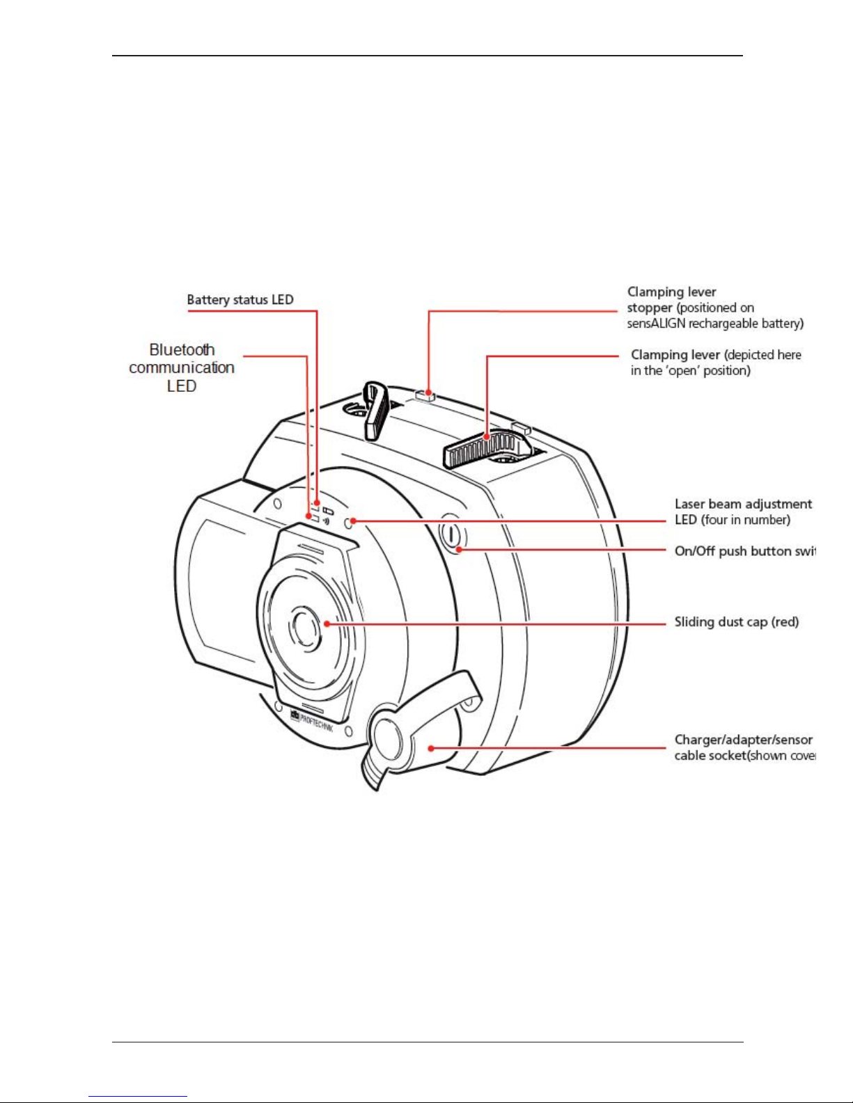
sensALIGN laser and sensor labelling
The labelling diagram represents both sensALIGN sensor and sensALIGN laser. It shows the
engraved symbols, markings and labels as they appear on the respective measurement head. The laser
safety labels are affixed on the housing of sensALIGN laser at the positions shown in the diagram.
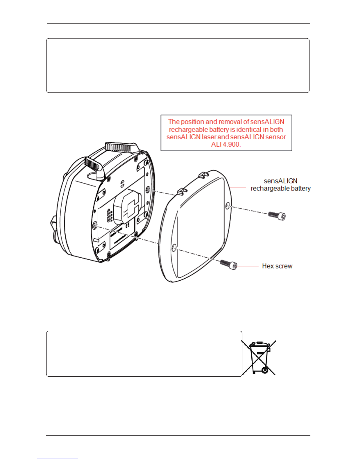
The rechargeable battery label is located on the rear of sensALIGN rechargeable battery.
FictionSoft 7
(Undefined variable: General.UserGuideTitle)

sensALIGN rechargeable battery
Both sensALIGN laser and sensALIGN sensor are powered using the sensALIGN rechargeable bat-
tery. The battery is charged via the charger/adapter socket using the sensALIGN charger/adapter. If
the battery capacity is greater than 50% [acceptable capacity for measurement], the battery status LED
on both sensALIGN laser and sensor lights up green for 2 seconds on switching on. During the char-
ging process, the battery status LED blinks green. When the battery is fully charged, the LED lights
steady green if the charger remains connected.
Activity sensALIGN laser battery
status LED sensALIGN sensor battery
status LED sensALIGN laser beam
active LED
Switch on
Lights up green for 3
seconds when battery run
time is > 10 hrs
Lights up green for 3
seconds when battery run
time is > 10 hrs Lights steady red when in
beam finder mode
Blinksredwheninmeas-
urement mode
Note that measuring can
take place with both
modes
Blinks green every 3
seconds when battery run
time is between5–10hrs
Blinks green every 3 seconds
when battery run time is
between1–5hrs
Blinks red every 3 seconds
when battery run time is
between1–5hrs
Blinks red every 3 seconds
when battery run time is
insufficient for longer meas-
urements
Blinks red constantly when
battery run time is < 1 hr Blinks red constantly when
battery run time is < 1 hr
8 Edition: (Undefined variable: General.Edition)
(Undefined variable: General.UserGuideTitle)

Charging bat-
tery
Blinks green when char-
ging Blinks green when charging
LED off
Lights steady green when
fully charged Lights steady green when
fully charged
Lights red when a failure
occurs during charging Lights red when a failure
occurs during charging
To replace the rechargeable batteries, use the provided 2.5 mm allen key [0 0739 1055] to undo the
two hex screws that affix the battery to either sensALIGN laser or sensor.
Used batteries should be disposed of in an environmentally-sound manner!
FictionSoft 9
(Undefined variable: General.UserGuideTitle)

Mounting components
Mounting brackets
Mount the brackets on either side of the coupling on either the shafts or on the solid coupling hubs,
and both at the same rotational position.
Please note the following in order to obtain the highest possible measurement accuracy and to avoid
damage to equipment:
Ensure that the brackets fit solidly onto their mounting surfaces! Do not use self-constructed
mounting brackets, or modify the original bracket configuration supplied by PRÜFTECHNIK
(for example, do not use support posts longer than those supplied with the bracket).
1. Choose the shortest support posts which will still allow the laser beam to pass over or through the
coupling. Insert the support posts into the bracket.
2. Fasten them in place by tightening the hex screws on the sides of the bracket frame.
3. Place the bracket on the shaft or coupling, wrap the chain around the shaft and feed it through the
other side of the bracket: if the shaft is smaller than the width of the bracket frame, insert the chain
from the inside of the bracket as shown in the diagram; if the shaft is larger than the bracket width,
insert the chain into the frame from the outside.
4. Catch the chain loosely on the anchor peg.
5. Turn the bracket thumbscrew to tighten the assembly onto the shaft.
6. Clip the loose end of the chain back onto itself.
The bracket should now be tight upon the shaft. Do not push or pull on the bracket to check, since
this could loosen its mounting.
To remove the brackets, loosen the thumbscrew, then remove the chain from its anchor peg.
10 Edition: (Undefined variable: General.Edition)
(Undefined variable: General.UserGuideTitle)

Mounting sensALIGN sensor and laser
Mount sensALIGN laser on the support posts of the bracket fixed on the shaft of the left machine (usu-
ally reference machine), and sensALIGN sensor on the support posts of the bracket fixed on the shaft
of the right machine (usually moveable machine) – as viewed from normal working position. Before
mounting both sensALIGN laser and sensor, make sure that the yellow clamping levers are in the
open position by placing them to the front. This enables components to slide onto the support posts.
Fix both sensALIGN laser and sensor onto the respective support posts by locking the yellow clamp-
ing levers. Lock the levers by pushing them backwards until they rest on the stoppers.
Ensure that the laser can pass over or through the coupling and is not blocked.
Both sensALIGN laser and sensor should be at the same height, as low as possible, yet just high
enough for the beam to clear the coupling flange. They should also visually appear to be rotationally
aligned to each other.
Make the final adjustments, loosening the brackets slightly if necessary, then rotating them and re-tight-
ening.
FictionSoft 11
(Undefined variable: General.UserGuideTitle)

Dimensions screen
1) Grayed out icons are disabled within the active screen. The 'Measure' icon is enabled after all
dimensions have been entered.
2) Tap the measurement units icon to set desired units.
Tap the dimension fields and enter all required dimensions. The user may elect to tap the
‘Next’ button to proceed to enter next dimension. Dimensions may be entered only when the dimen-
sion field is highlighted green.
Therotateviewicon is used to rotate the view of the machines and mounted components on
the display.
Machine and coupling properties may be edited by tapping the respective machine or coupling.
When all required dimensions have been entered, the ‘Measure’ icon appears.
Tap to proceed with measurement.
Machine properties
Swipe the machine carousel up or down to select desired machine. Position desired machine at the
centre of the carousel then tap to confirm selection and return to the dimensions screen.
12 Edition: (Undefined variable: General.Edition)
(Undefined variable: General.UserGuideTitle)

Thermal growth1
The Thermal growth screen is accessed by tapping "More".
Thermal growth values can be entered only when the type of mounting is either machine feet or bear-
ing or V-shaped support.
To enter any specified thermal growth value at the required feet position, tap the corresponding value
box then proceed to enter the thermal growth value using the onscreen keyboard. Cycle through the
value boxes using or alternatively tapping the desired feet position.
Thermal growth values are activated by tapping "On". When thermal growth values are enabled, the
corresponding machine [1]within the inset at the top-right corner appears in orange. After thermal
growth values have been entered, tap to proceed.
Coupling properties
Tap either the top or bottom arrow to select desired coupling type.
1Movement of shaft centerlines associated with or due to a change in machinery temperature between
the idle and operating conditions.
FictionSoft 13
(Undefined variable: General.UserGuideTitle)

Initializing sensor
The hint "Communication error" [1] suggests that the sensor has not been initialized although the laser
beam may have been correctly adjusted.
Tap either the detector area [2] or the sensor/laser area [3]to access the menu item 'Sensor list'.
Tap menu item 'Sensor list' [1] to view scanned sensors. The hint 'Bluetooth scanning started' [2]
appears during the scanning process. As soon as the sensor is detected, it is listed down and a green
bold dot [3] appears next to the detected sensor.
Initialize the sensor by tapping the listed sensor. A bold blue dot [1] signifes that sensor is initialized.
14 Edition: (Undefined variable: General.Edition)
(Undefined variable: General.UserGuideTitle)

Laser beam adjustment
Here is some general text for a topic. Replace this with your own content.
FictionSoft 15
(Undefined variable: General.UserGuideTitle)

XY View
The XY View function is used to facilitate the centering of the laser beam on the two sensALIGN
sensor detector planes before proceeding with measurement.
1) Tap the detector area shown to directly access the XY View screen.
2) The XY View screen may be accessed indirectly using the menu item "XY View" which appears
when the "sensor/laser area is tapped.
3) The XY View screen may be accessed indirectly using the menu item "XY View" which appears
when the laser is tapped.
The two sensor detector planes are displayed on the XY View screen. Center the laser beam dots in
both planes using both beam position thumbwheels. In some cases it may be necessary to move
sensALIGN sensor along the support posts or sideways by loosening the chain type bracket and
slightly rotating it.
The "Set to zero" function may be used to check the effect of environmental and machinery vibration
on the measurement. Note that the "Set to zero" is active only when the laser beam status [1] is "OK"
or "Centered".
16 Edition: (Undefined variable: General.Edition)
(Undefined variable: General.UserGuideTitle)

If the laser beam status is "OK" or "Centered" [1] tap "Set to zero" [2] to set the XY values of the two
detector planes to 0,0. These values are then monitored to check the stability of the values. Tap "Abso-
lute" to return to the absolute values.
Note that the menu items on the screen may be used to display following items:
Sensor list – displays serial number of sensors detected or previously used, as well the interface used
for connection
Laser properties – displays detailed information of sensALIGN laser in use
Sensor properties – displays detailed information of sensALIGN sensor in use
FictionSoft 17
(Undefined variable: General.UserGuideTitle)

18 Edition: (Undefined variable: General.Edition)
(Undefined variable: General.UserGuideTitle)

Measurement modes
The following measurement modes are available for horizontal machine configurations:
IntelliSWEEP – This is the measurement mode used to measure standard coupled machines. It detects
error influences such as coupling play, rough rotation and environmental vibration, and automatically
eliminates the induced errors.
Multipoint – This is the mode used to measure nonrotatable shafts, sleeve bearings [journal (radial)
bearings], white metal bearings , shafts that are hard to turn, shafts with herky-jerky rotation, situations
with long spans or severe misalignment that will readily cause the beam to fall out of range
Static – This mode is used to measure uncoupled shafts.
The desired measurement mode is selected while in the measurement screen.
Tap the measurement mode header [1] to access the measurement mode carousel.
Tap either the top or bottom arrow to select desired measurement mode.
FictionSoft 19
(Undefined variable: General.UserGuideTitle)

In the above example, Multipoint measurement has been selected. The quality of the measurement
may be displayed either as a measurement standard deviation1(SD) or measurement quality2
factor. The averaging is set by tapping the 'Averaging' button.
Averaging
In certain industrial conditions, it may be necessary to increase the number of measurements (recorded
laser pulses) to be averaged when taking readings to attain the desired accuracy. Particular cases
include environments with increased machinery vibration. An increased averaging also improves the
accuracy when measuring sleeve bearings, white metal bearings and journal bearings.
Averaging is possible in ‘point’ measurements such as ‘Multipoint’ and ‘Static mode’.
Set the averaging by tapping the 'Averaging' button [1]. A scale [2] used to set the averaging value
appears on the screen. Tap desired averaging value which then appears in the 'Averaging' button [1].
1Standard deviation describes how closely a group of datra points are clustered around the average of
those data points. The smaller the standard deviation, the better the quality of the data collected.
2displays quality of measurement based on following measurement and environmental factors:
rotataion angle, ellipse standard deviation, environmental vibration, rotation evenness, angle rotation
inertia, rotation direction, rotational speed and filter output
20 Edition: (Undefined variable: General.Edition)
(Undefined variable: General.UserGuideTitle)
Other manuals for Rotalign Touch
1
Table of contents