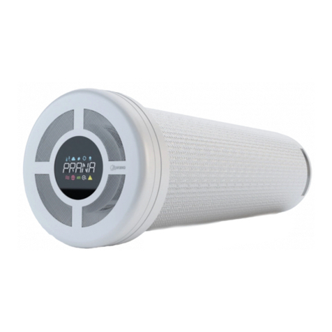
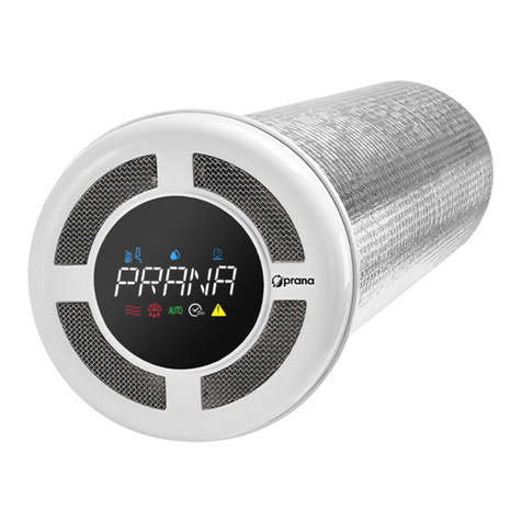
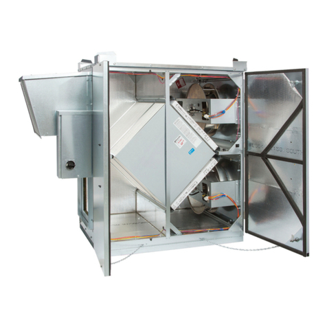
prana 340S User guide

OPTIONS AND
DIMENSIONS
INDUSTRIAL RANGE
PRANA 340S
Use the QR code or visit the website:
http://prana.help/p023 to overview useful infor-mation such as
ventilation system information, owner's manual and other.
• Read all safety information carefully to ensure safe and proper use of the device.
MODEL RANGE: PRANA 2022®
PL


CONTENTS
WARNING AND SAFETY MEASURES ........................................ 4
SYSTEM CONDITIONAL ASSIGNMENT STRUCTURE ............ 8
DESIGN VARIANTS AND DIMENSIONS ................................. 10
PRANA-340S TYPE1 ................................................................... 10
PRANA-340S TYPE2 .................................................................... 16
PRANA-340S TYPE3 .................................................................... 21
PRANA-340S TYPE4 ............................................................. 27
PRANA-340S TYPE5 ............................................................. 31
PRANA-340S TYPE6 ............................................................. 37
PRANA-340S TYPE7 ............................................................ 43

4
WARNING AND SAFETY MEASURES
• The ventilating system can be used by children aged 8
years and older and by people with physical, sensory, mental
disabilities or lack of experience and knowledge if they are
supervised or instructed to operate the unit in a safe manner
and understand the hazards involved in its use. Do not allow
children to play with the ventilation system.
Installation, cleaning, and maintenance should not be
performed by children.
• The fan inside the device rotates during operation. Avoid
putting foreign objects inside the device during operation.
Doing so may result in personal injury.
• The unqualified user must not install, move, dismantle,
modify or repair the ventilation system himself.
• Begore the use make sure that the installation complies
with the mechanical and electrical regulations which are in
force in the country where the installation was carried out.
• Do not install heating equipment for air intake by a
ventilation system.
Incomplete combustion products can cause an accident.
• Installation by unqualified people can result in poor
performance, damage to the ventilation system, and
accidents.
• If the ventilation system is used in the same room as
other ventilation systems in operation, the performance of
the unit may differ from the stated performance.

5
• The presence of excessive wind pickup can affect the
performance of the ventilation system.
• Avoid damaging of the ventilation system.
• Warnings and precautions when installing the PRANA
ventilation system are described in the installation manual.
• If the heating elements from a third party supplier
are connected to the PRANA system control unit, the
manufacturer is not responsible for the proper operation of
both devices.
The heating elements, which may (optionally) be supplied
by the manufacturer, undergo a technical preparation stage
for proper operation.
• The air conveyed must not contain combustible or
explosive mixtures, chemically active vapors, sticky
substances, fibrous materials, coarse dust, soot, grease or
media that promote the formation of harmful substances
(poison, dust, pathogens).
• The unqualified user must not install, move, dismantle,
modify or repair the ventilation system himself.
• Before installation, make sure that there is no mechanical
damage to the structure and fasteners.
• If damage occurs, immediately de-energize the system
with a circuit breaker.Continued use may cause smoke, fire,
electric shock or injury.

6
Contact the manufacturer's service center or dealer in
your area for repair.
• It is not allowed to mount the connection heater with
the box downwards (danger of condensation and short-
circuiting of the wiring).
• Do not twist, damage or change the power cord. Do not
expose it to heat or place heavy objects on it. Doing so may
cause a fire or an electric shock.
• Do not block the intake or exhaust air passages as this
will reduce the performance of the system and could result
in stopping and/or smoke, fire, electric shock or injury.
• The recuperator is connected by means of insulated
strong conductors (cables, wires) with a cross-section of
0.5-0.75mm2. All wiring must be installed by a qualified
electrician in accordance with the Electrical Installations
Code.
• Heaters must be installed in a duct of similar diameter
(size). The minimum allowable distance between heater and
recuperator is at least 0.5 m of metal duct.
• The duct heaters are designed for a minimum airflow
rate of 1.5 m/s and a maximum exhaust air operating
temperature of 40 °C.
• Before performing any maintenance operations, de-
energize the unit (turn off the main power switch and wait
for the fans to of the fans to stop completely).
• Heaters cannot be insulated with thermal insulation
materials.

7
• The manufacturer is not responsible for the installation
that is carried out by an unqualified specialist (or group of
specialists) and all subsequent consequences connected
with it.
Incorrect installation will invalidate the warranty.
• The air ducts must be equipped with grills or other device
preventing free access to the fans.
• To avoid reverse draught in rooms where fireplaces,
gas heaters and other equipment producing or different
gas mixtures are in operation, the "Separate control" mode
must not be used.

8
SYSTEM CONDITIONAL ASSIGNMENT STRUCTURE
• PRANA-340S TYPE1 - Indoor module with using 200 mm
side spigots for circular duct connection. The front center
spigot of the system with 200 mm diameter is used to
connect the supply air duct in the room, and the rear center
spigot with 200 mm diameter to connect the exhaust air
duct from the room;
• PRANA-340S TYPE2 - Indoor module with the use of side
spigots with a diameter of 200 mm to connect the circular
duct. The front center spigot of the system with a diameter
of 200 mm is used to connect the exhaust duct in the room,
and the rear center spigot with a diameter of 200 mm to
connect the air intake duct from the street;
• PRANA-340S TYPE3 - Wall module with side spigots of
200 mm diameter to connect the circular duct. The system's
front 200 mm center spigot is used to connect the room
supply air duct, and the rear 200 mm center spigot is used
to connect the exhaust air duct from the room;
• PRANA-340S TYPE4 - Indoor module with side spigots
use 204x60 mm for the connection of a rectangular duct.
The front center spigot of the system with a 204x60 mm is
used to connect the supply duct to the room, and the rear
center spigot with a diameter of 200 mm is used to connect
the exhaust duct from the room;
• PRANA-340S TYPE5 - Indoor module using side spigots
204x60 mm diameter used to connect the rectangular duct.

9
The front center spigot of the system with a 204x60 mm is
used to connect the exhaust duct in the room, and the rear
center spigot with a diameter of 200 mm is used to connect
the air intake duct from the street;
• PRANA-340S TYPE6 - Wall module PRANA-340S with the
use of side spigots 204x60 mm for connecting a rectangular
duct. The front center spigot of the system with a 204x60
mm is used to connect the supply duct in the room, while the
rear center spigot, 200 mm in diameter, is used to connect
the exhaust air duct from the room;
• PRANA-340S TYPE7 - Wall module PRANA - 340S without
using side spigots for duct connection, air intake is made
through a 40 mm wide slot, along the outside diameter of
the casing.

10
DESIGN VARIANTS AND DIMENSIONS
PRANA-340S TYPE1 - Indoor module with using 200 mm
side spigots for circular duct connection. The front center
spigot of the system with 200 mm diameter is used to
connect the supply air duct in the room, and the rear center
spigot with 200 mm diameter to connect the exhaust air
duct from the room;
Main dimensions. Top view.
1210
200
340
200
350
200
200
230 230
550

11
1210
210
200
200
340
350
550
L/2 L/2
ø200
250
50
85
ø200
The main dimensions. Side view.
The main dimensions. Side view.
H
B
A
CD
E
F
G
A-Inflow of air into the
room
B-Terminal box
C-Room air intake
Ø200 mm
D-Energy intake Ø200 mm
Ø200 mm
E-Building ceiling
F-Condensate drain
pipe Ø10 mm
G-System brackets
H-Exhaust air outlet to
the outside Ø200 mm

12
Assignment of system connections. Top view.
A
C
B
D
A-Inflow of air into the room.
B-Room air intake. Use the necessary (and) or install
a blanking plug. Use one/two Ø200 mm required
connections.
C-External air intake Ø200 mm. Use the required (and)
or install a blanking plug. Use one/two Ø200 mm
connection(s).
D-Exhaust air discharge to the outside.

13
A
B
D
E
I
J
C
H
G
F
E
D
BF
G
D
C
B
A
Exterior placement. Isometric scheme.
Assignment of system connections. Isometric diagram.
A-P2 Ø250 mm
B-Installation of flexible
insertion Ø200 mm
C-B4 Ø250 mm
D-Muffler
Ø200/250 mm
A-Room air inflow Ø200mm.
B-Air intake from room
Ø200 mm.
C-Control box.
E-PRANA -340S
F-P1 Ø200/250 mm
G-Filter box Ø200/250 mm
H-Outer grille P1
I-В3 Ø200/250 mm
J-External grille B3
D-External air intake
Ø200 mm.
E-System fixing.
F-Covering of the building.
G-Exhaust air outlet to the
outside Ø200 mm.

14
Min 2000
E
H
G
F
L
B
I
A
C
J
K
M
D
Min 1000
Recommended connection diagram for ducts.
1 connection.
A-P2 Ø250 mm
B-B4 Ø250 mm
C-Electric duct heater
Ø200/250 mm
D-Install flexible insertion
Ø200 mm
E-PRANA -340S
F-Muffler Ø200/250 mm
G-Install flexible plug
Ø200 mm
H-Insert plugs
Ø200 mm
I-P1 Ø200/250 mm
J-Interior grid P1
K-Filter box
Ø200/250 mm
L-В3 Ø200/250 mm
M-External grille B3

15
F
G
J
D
B
B
H
A
C
K
I
L
E
Min 2000
Min 1000
Recommended connection diagram of the air ducts.
2 connections.
L-External grille B3
D-Install flexible connector
Ø200 mm
G-Insert blanking plug
Ø200 mm
I-Filter box Ø200/250 mm.
F-PRANA-340S mm
E-Muffler Ø200/250
J-B4 Ø200 mm
C-Electric duct heater
Ø200/250 mm
A-P2 Ø250 mm
H-P1 Ø200/250 mm
K-External grille P1

16
1130
200
340
200
350
200
200
190 190
550
PRANA-340S TYPE2 - Indoor module with the use of side
spigots with a diameter of 200 mm to connect the circular
duct. The front center spigot of the system with a diameter
of 200 mm is used to connect the exhaust duct in the room,
and the rear center spigot with a diameter of 200 mm to
connect the air intake duct from the street;
Main dimensions. Top view.

17
1130
170
200
200
340
350
550
L/2 L/2
ø200 ø200
250
50
85
475
190190
170
Assignment of connections of the system. Side view.
The main dimensions. Side view.
H
C
A
DE
B
F
G
A-Fence from room Ø200 mm
B-Building ceiling
C-Terminal box
D-Enhalation of air into Ø200 mm
E-Exhaust air outlet to the outside
Ø200 mm
F-Condensate drain
pipe Ø10 mm
G-System brackets
H-Box for outside air
Ø200 mm

18
A
C
B
D
Assignment of system connections. Top view.
A-Extract air from Ø200 mm
B-Room air inlet Ø200 mm
C-Exhaust air outlet to the outside Ø200 mm
D-Exhaust air intake Ø200 mm

19
Assignment of system connections. Isometric diagram.
External positioning. Isometric scheme.
B
F
E
C
G
E
D
C
A
C
H
E
G
F
A
D
B
I
K
J
A-Extract air from
Ø200 mm
B-System bracket
C-Room air inlet Ø200 mm
D-Terminal box
E-Exhaust air outlet to the
outside Ø200 mm
F-Building ceiling
G-Exhaust air intake
Ø200 mm
A-P2 Ø250 mm
B-Electric duct heater
Ø200/250 mm
C-B4 Ø250 mm
D-Muffler Ø200/250 mm
E-PRANA -340S
F-Filter box Ø200/250 mm
G-P1 Ø200/250 mm
H-Install flexible insert
Ø200 mm
I-External grid P1
J-B3 Ø200/250 mm
K-External grille B3

20
F
D
G
B
C
I
A
J
H
K
E
Min1500
Duct connection diagram. 1 connection.
A-B4 Ø250 mm
B-P2 Ø250 mm
C-Electric heater
Ø200/250 mm
D-Muffler Ø200/250 mm
E-Install flexible insert
Ø200 mm
F-PRANA -340S
G-Filter box
Ø200/250 mm
H-P1 Ø200/250 mm
I-B3 Ø200/250 mm
J-External grille B3
K-External grille P1
Other manuals for 340S
2
Table of contents
Other prana Fan manuals
Popular Fan manuals by other brands
Carrier
Carrier HRVCCSVU User's information manual

Harbor Breeze
Harbor Breeze TEX52MBK5C1L user manual
VENTOMAXX
VENTOMAXX Z-WRG RONDO-Plus Assembly and operating instructions

Faro Barcelona
Faro Barcelona Lantau installation guide

Sulion
Sulion MARINA 2172200 instructions
Sinbo
Sinbo SF 6710 instruction manual

