Precision Acoustics DPSU Instruction sheet

PRODUCT INSTRUCTIONS
Precision Acoustics Ltd Hampton Farm Business Park, Higher Bockhampton, Dorchester, Dorset DT2 8QH, UK
Differential membrane hydrophone
Document version
Date of issue
2.2
17/03/2020
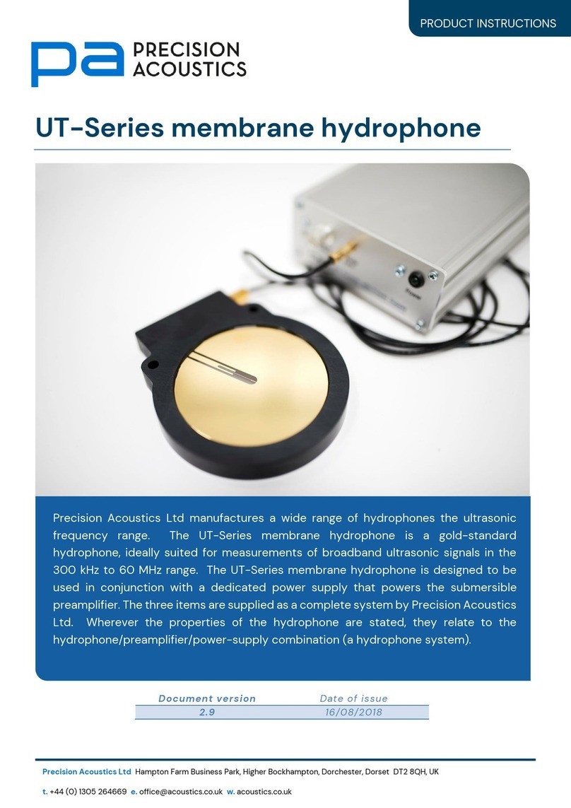
Precision Acoustics Ltd manufactures a wide range of hydrophones the ultrasonic
frequency range. The Differential membrane hydrophone is a gold-standard
hydrophone, ideally suited for measurements of broadband ultrasonic signals in the
500 kHz to 100 MHz range. The Differential membrane hydrophone is designed to be
used in conjunction with a dedicated power supply that powers the fully differential
internal preamplifier. The two items are supplied as a complete system by Precision
Acoustics Ltd. Wherever the properties of the hydrophone are stated, they relate to
the hydrophone/power-supply combination (a hydrophone system).

PRODUCT INSTRUCTIONS
INTRODUCTION
The Differential membrane hydrophone comprises a single layer of PVDF on which gold electrodes
have been deposited such that, after polarisation only a small central circular area is piezo-electrically
active. This gives a sensing device, which is acoustically transparent and can be used to plot the
pressure distribution of ultrasonic fields. Incorporated within the membrane ring is an
instrumentation amplifier. The power supply included with the membrane hydrophone provides
power to the amplifier and transfers the signal to an oscilloscope through the 50 Ωtermination.
PVDF hydrophones have an inherently wide bandwidth and Differential membrane hydrophones have
been calibrated by NPL, London over the frequency range 300 kHz to 60 MHz.
Further information on making acoustic measurements with hydrophones can be found on our
website (http://www.acoustics.co.uk). In addition, Precision Acoustics Ltd offers training courses
covering many aspects of acoustic measurement techniques and practices.
Unpacking the hydrophone system
Each Differential membrane hydrophone system contains several components. Carefully remove the
packaging and identify the following:
•Differential membrane hydrophone
•Membrane hydrophone PSU
•Calibration certificate (printed)
•Mains inlet cable

PRODUCT INSTRUCTIONS
PREPARING FOR MEASUREMENT
Mounting the hydrophone
Hydrophones should be secured in a fixture that
ensures the hydrophone can be moved around
in a water tank to align it with the acoustic
source. This could be a simple mount that
secures the hydrophone via the two locating
holes in the membrane ring or a more
comprehensive mount capable of providing
rotational adjustment.
An example of a Differential membrane
hydrophone within a mount offering 3
independent rotation adjustments is shown
alongside. This mount is available from Precision
Acoustics Ltd as an optional extra upon request.
It is recommended that all hydrophones receive
1h soaking before use. It is recommended that
the hydrophone is placed in the water tank at
this stage before completing the rest of the
setup process.
IMPORTANT NOTE
The membrane hydrophone PSU supplies an amplifier which is embedded in
the hydrophone ring. It is mains operated and should be positioned away
from water and connected to the mains supply via a Residual Current Device
(RCD).
WARNING: DO NOT position it on moving parts of the test tank system.
WARNING: If the membrane hydrophone PSU falls into the water tank,
disconnect from mains BEFORE removal from the water.
If the equipment is used in a manner not specified in this document, the
protection provided by the equipment may be impaired
Only replace the mains cord with one of sufficient current rating
WARNING: The membrane hydrophone must be handled with
extreme care. The membrane is very delicate and must
never be touched by hand or rubbed with any form of cloth
or tissue.

PRODUCT INSTRUCTIONS
Connecting the hydrophone system
Once the connections above are made, mains power should then be applied to the membrane
hydrophone PSU and the data acquisition device. The hydrophone system is now ready for operation.
Please see the section “After measurements are complete” for information about care of your
hydrophone system after use.
MEMBRANE
HYDROPHONE PSU
50 INPUT DATA
ACQUISITION DEVICE
© Keysight Technologies
Image shown for illustrative purposes only
MEMBRANE
HYDROPHONE
Bespoke cable on
membrane hydrophone
50 BNC
cable

PRODUCT INSTRUCTIONS
ORIENTATION AND ALIGNMENT
All hydrophones exhibit a directional response and the maximum hydrophone signal will be received
when the plane of the hydrophone active element is orthogonal to the acoustic axis of the transducer
(as shown in the image below). If the membrane hydrophone is rotated about the X or Y axes, there
may be a reduction in the amplitude of received signal, even if the active element remains on the
acoustic axis of the source. This directionality effect will be more noticeable at higher frequencies
and with larger hydrophone active elements.
FINDING A HYDROPHONE SIGNAL
▪For large amplitude low frequency signals generated by single element transducers, this is not
generally a problem. However, for high frequency, narrow beam transducers this can take a
significant time, even if you do follow the steps suggested below. This can be a particular
problem with differential membrane hydrophones where the active area is not clearly visible.
▪Set DAQ for a higher sensitivity (e.g. 5-10 mV/div), which can always be changed later.
▪Visually align hydrophone and transducer. (assuming the optical axis is close to acoustic axis)
▪Triggering. Check that your DAQ system is triggering properly. Particularly if you are triggering
from the acoustic signal, check that you set the trigger level is to a low level since the acoustic
signal may be small.
▪Assess the transducer–hydrophone distance and use to calculate approximate
propagation delay and set the timebase delay on your DAQ accordingly. Consider using a
deliberately reduced timebase delay in conjunction with a larger time per div setting to
acquire a longer time trace thereby ensuring that the required signal will be “in there,
somewhere”. Once found refine settings accordingly.
▪Although the signal in the far field of a transducer should be more smoothly varying, a highly
directional beam can be difficult to find. Instead, try moving hydrophone close to surface of

PRODUCT INSTRUCTIONS
transducer and locating signal there. Once signal is found, move gradually further away from
transducer (aligning hydrophone as necessary on the way) until desired field position is
achieved.
▪Noise. Where there is poor signal to noise ratio (SNR), it can sometimes be difficult to locate
signal.
oIf you believe hydrophone position is correct, use time domain averaging to improve
SNR. If signal is buried in noise, it should reveal itself.
oIf averaging is not available on oscilloscope, try moving hydrophone slightly backwards
and forwards along the acoustic axis of the transducer. This should cause the signal to
move on the screen of the DAQ and the human eye can sometimes recognise a moving
pattern easier than a stationary one.
CONVERTING HYDROPHONE VOLTAGE TO ULTRASONIC PRESSURE
A hydrophone produces an electrical output signal in response to the surface integral of the acoustic
pressure received over its active element. There may not be a linear relationship between the
acoustic pressure stimulus and the voltage response. In fact, the relationship is almost always
frequency dependent and a conversion process will be required to obtain the acoustic pressure
signal from the hydrophone output voltage. A detailed description of this process can be found within
references [1] [2] and [3]. When the source of ultrasound is only operating at one frequency (e.g.
continuous wave) or with very narrow bandwidth (e.g. sinusoidal tone burst) the relevant IEC standard
[4] states that the pressure signal, p(t), can be calculated from the measured hydrophone voltage,
v(t), according to the relationship
where M(fawf)= sensitivity of a hydrophone at the acoustic working frequency of the source. More
generally however, and especially if the acoustic signal is broadband, the pressure signal should be
calculated according to the relationship
where and are the Fourier and inverse Fourier transforms and M(f) = sensitivity of a hydrophone
FINDING THE BEAM MAXIMUM
Many acoustic measurements require the maximum value of the acoustic pressure field to be located.
The following two steps are required to maximise the hydrophone signal.
•Correct for directional response of hydrophone –consider the hydrophone active element as
lying in the X-Y plane (Z direction coming normally out of active element). There will be a
directivity pattern associated with both the X and the Y axes (although hopefully the patterns
are the same). First rotate about the X-axis to obtain maximum signal, and then repeat around
the Y Axis.

PRODUCT INSTRUCTIONS
•Find the pressure field maximum –centred on your current position, move the hydrophone
along a line parallel with the X-axis. Move the hydrophone to the location of the field maximum
along that line. Repeat this type of line scan alignment in the orthogonal direction of the Y-
axis. The hydrophone should now be at the position of a maximum. Ensure that your line scans
are long enough to capture the global maximum rather than a local maximum. Repeat with
finer scans if required
•If your hydrophone mount does not have truly independent degrees of freedom there may be
some translation of the hydrophone tip during rotation, so you may have to iterate through
the above two steps.
ALIGNING THE TRANSDUCER BEAM
To align the acoustic axis of the transducer with one of the axes of your hydrophone positioning
system.
•Place hydrophone close to the near field /far field separation distance
of the transducer and
conduct a line scan in the X direction, centred on your current position. Note the position of
the maximum.
•Move the hydrophone a known distance further into the far field of the transducer and conduct
a second, centred line scan. Once again note the position of the maximum.
•Use trigonometry to ascertain the angular misalignment of the acoustic axis of the transducer,
and rotate the transducer to correct accordingly.
•Repeat this process for the Y direction.
•The transducer may not have well behaved field symmetry and the positions of the maxima
may appear to vary as a function of angle, so it is best to repeat the above process for a
second iteration, to fine tune the alignment.
AFTER MEASUREMENTS ARE COMPLETE
Once measurements are complete please observe the following steps
•Disconnect the membrane hydrophone PSU from the main supply
•Remove the Differential membrane hydrophone from the water.
oRinse the membrane with de-ionised water. Do not attempt rub the membrane with a
cloth/tissue to “clean” it.
•Leave the hydrophone to air dry in a secure location where it cannot get damaged.

PRODUCT INSTRUCTIONS
TROUBLESHOOTING AND FAQ
Troubleshooting
The Membrane hydrophone PSU has a green LED power indicator on the front panel. If this is not
illuminated then the most likely fault is a blown fuse on the membrane hydrophone PSU. If this needs
replacing then a 0.2 A, Quick blow, 20 mm fuse should be used.
Provided the membrane is not physically damaged, there are no electrical or mechanical checks
which will determine whether the differential membrane hydrophone is working correctly. It can only
be checked acoustically. Ensure that the power supply is working and connected to the membrane
cable. Then follow the instructions above for finding a signal. If no signal can be found and you are
certain that your transducer is working correctly, there may be a fault with the membrane hydrophone
system should be returned to Precision Acoustics for inspection. It is unlikely that the membrane
can be repaired but a generous discount will be offered against a new membrane.
Frequency asked questions (FAQ)
▪What liquids can I used my hydrophone in?
oThe Differential membrane hydrophone is designed for use in water with a conductivity
of < 5 μS/cm. Degassing so that dissolved gas content is < 5 ppm is also
recommended.
oFor high amplitude fields the dissolved gas limit changes from recommended to
required and the level drops to < 2.5 ppm. Failure to do so may result in cavitation
damage to the hydrophone which is NOT covered by our warranty.
oHydrophones can be used in castor oil or mineral oil. The hydrophone is constructed
from PVDF which although resilient can be damaged by some organic solvents. If any
medium other than water is used, the calibration figure will not be valid since the
medium will have changed the electrical and acoustical loading conditions on the
hydrophone
▪Do I have to soak the hydrophone?
oAll hydrophones should be soaked before use. Our recommendation is to soak for 1
hour so that the output stabilises before measurements are taken, although most
hydrophones stabilise after about 20 minutes.
▪How long can I leave the hydrophone in water?
oHydrophones should be removed from the water whenever they are not in use and we
advise that if they are left immersed longer than 24 hours they are removed as soon
as possible and dried out.
▪How do I dry the hydrophone?
oRinse the hydrophone in distilled water after use and leave to air dry or place in a warm
oven at no more than 50 °C. Do not touch the membrane surface.

PRODUCT INSTRUCTIONS
▪How do I clean the calcium carbonate deposits from the hydrophone?
oImmerse the hydrophone in lemon juice and then rinse in distilled or running water.
Never use a cloth/towel/abrasive cleaner on the membrane
▪Do I have to terminate the hydrophone output in 50 Ω?
oThe input and output from your measurement equipment should be terminated with
50 Ω. Cables connecting to/from the hydrophone system must have a characteristic
impedance of 50 Ω. If your data acquisition equipment has only a high impedance
termination then you much use an inline through 50 Ωterminator to achieve the correct
impedance
POWER SUPPLY SPECIFICATION
Model number
DPSU
AC supply voltage
Wide range input: 100/120V, 0.2A at 60Hz or
230/240V, 0.2A at 50Hz AC.
(switchable)
Input impedance
50 Ω
Output impedance
50 Ω
Power consumption
2.4 W
Operating temperature range
0 °C to 50 °C
Relative humidity (recommended)
50%
Terminations
Custom 5-way connector (input)
BNC (output)
Maximum dimensions
185 mm (length)
109 mm (width)
45 mm (height)
Weight
925 g
Note: Connection to a power supply must be made via the mains cord supplied by Precision
Acoustics Ltd. If another cord is to be used it must conform to IEC60320-1 or BS1363-1: 2016 (UK
only).
PRODUCT SUPPORT
Disclaimer
Use of either the hydrophone or its power supply in a way not in accordance with information
provided in these product instructions may be hazardous. Precision Acoustics does not accept
liability for incidents occurring as a result of improper use and recommends these instructions MUST
be followed.
All information is based on results gained from experience and tests, and is believed to be accurate
but is given without acceptance of liability for loss or damage attributable to reliance thereon as
conditions of use lie outside the control of Precision Acoustics Ltd.

PRODUCT INSTRUCTIONS
Warranty
Warranty will be for 12 months against defect of hardware component or manufacture only.
If a warranty claim is made on devices that have been calibrated at NPL London, the charge for
calibration of the replacement device is pro-rata against the used part of the original device’s 12-
month calibration.
Warranty replacement after
Calibration period remaining
Discount on recalibration charge
3 months
9 months
75%
8 months
4 months
33%
Contact
Further advice and technical assistance can be obtained from our Applications Engineers
Address: Precision Acoustics Ltd, Hampton Farm Business Park, Higher
Bockhampton, Dorchester, Dorset DT2 8QH
Email: technical@acoustics.co.uk
Tel: +44 1305 264669
Fax: +44 1305 260866
Terms and conditions
PA terms & conditions are available at https://www.acoustics.co.uk/company/terms-and-conditions/
REFERENCES
[1]
A. Hurrell, "Voltage to Pressure Conversion: Are You Getting "Phased" by the Problem?," J. Phys:
Conf. Ser., vol. 1, pp. 57-62, 2004.
[2]
V. Wilkens and C. Koch, "Improvement of hydrophone measurements on diagnostic ultrasound
machines using broadband complex-valued calibration data," J. Phys: Conf. Ser., vol. 1, 2004.
[3]
A. M. Hurrell and S. Rajagopal, "The practicalities of obtaining and using hydrophone calibration
data to derive pressure waveforms," IEEE Trans UFFC., vol. 64, pp. 126-140, 2017.
[4]
IEC, 62127 Ultrasonics - Hydrophones - Part 1: Measurement and characterisation of medical
ultrasonic fields up to 40 MHz, 2013.
Table of contents
Other Precision Acoustics Recording Equipment manuals
Popular Recording Equipment manuals by other brands
CALEFFI
CALEFFI SATK12313 INSTRUCTIONS FOR INSTALLATION, COMMISSIONING AND MAINTENANCE

Nat
Nat AA12S Series Compact Audio Controller SM69 Installation and operation manual
Fujiya
Fujiya EX-311 user manual

ShowMagic
ShowMagic SLX Series user manual

B&G electronics
B&G electronics PW-50 Installation and operation manual
socomec
socomec DIRIS Digiware M-50 instruction manual
