Precision Digital Corporation PD9501 User manual

www.predig.com
PD9501
Multi-Function Calibrator
PRECISION DIGITAL CORPORATION
FEATURES
• Measure and Source T/Cs, RTDs, Ohms, Current, Voltage
• Compact & Lightweight
• Battery or USB Powered
• Descriptive LCD Display
• 24 V Power to Drive the Transmitter
• Auto Stepping & Auto Ramping
• Selective Auto O Mode
• LCD includes an LED backlight

2www.predig.com
PD9501 Multi-Function Calibrator
OVERVIEW
This PD9501 Multi-Function Calibrator has a variety
of signal measurement and output functions, including
voltage, current, thermocouple, and RTD.
Main Function
Voltage Signal: 0-30 V, 0-25 mV, 0-100 mV output and
measurement.
Current Signal: Active and passive 0-25 mA, 4-20 mA
output and measurement.
Thermocouple: K, E, J, T, R, B, S, N output and
measurement. Note: Output Range Starts from 0°C
RTD: PT100 output and measurement.
Ohms: Output and measurement
INPUT SIGNAL RANGE ACCURACY RESOLUTION NOTE
DC Voltage 20 mV 0.00-24.00 mV ±0.2% 0.01 mV
100 mV 0.0-100.0 mV ±0.2% 0.1 mV
VOutput:
0.00-15.00 V
±0.2% 0.01 V Output:
Maximum current 30 mA
Measurement:
Input Impedance 1.2 M Ω
Measure:
0.00-30.00 V
±0.2% 0.01 V
DC Current mA 0.00-24.00 mA ±0.2% 0.01 V Output:
Maximum load 750 Ω
Measurement:
Input Impedance 100 Ω
4-20 mA 4/8/12/16/20 mA ±0.2% 0.01 mA
Passive Current mA 0.00-24.00 mA ±0.2% 0.1 V Output: External power 16-30 V
Power Output 24 V
LOOP
24V/16 V ±10% Drive Current:
24 mA
Thermocouple K -270 to 1372°C ±1% 1°C The output or measurement
can not be less than the Cold
Junction Temperature.
Output:
Range Starts from 0°C
E -270 to 1000°C ±1% 1°C
J -210 to 1200°C ±1% 1°C
T -270 to 400°C ±1% 1°C
R -50 to 1768°C ±1% 1°C
B 0 to 1820°C ±1% 1°C
S -50 to 1768°C ±1% 1°C
N -270 to1300°C ±1% 1°C
Ohms ΩOutput:
15.0-400.0
Measure:
0.0-400.0
±0.2% 0.1 Ω Excitation Current:
Min of 0.5 mA, Max of 3 mA
RTD PT100 -199.0 to 650.0°C ±0.2% 0.1°C
Accuracy Specications
The PD9501 includes a convenient storage case.

3www.predig.com
PD9501 Multi-Function Calibrator
FUNCTIONS
MEASURE
SIGNAL SIGNAL
RANGE RANGE
OUTPUT
PROGRAM
WAVEFORM
COLDEND
4
5
6
8
7
9
1 2 3
Terminal Blocks
① Common (Black)
② Output Terminal (Yellow)
③ Measurement Terminals (Red)
Buttons
④ Numeric Modier Keys
Increase or decrease values
Toggle numeric decimal points
Toggle value plus or minus
⑤ Measurement Function Keys (Blue)
[Signal]: toggle signal type
[Range]: toggle measurement range
[Measure]: open/exit measurement function
MEASURE
SIGNAL SIGNAL
RANGE RANGE
OUTPUT
PROGRAM
WAVEFORM
COLDEND
4
5
6
8
7
9
1 2 3
MEASURE
SIGNAL SIGNAL
RANGE RANGE
OUTPUT
PROGRAM
WAVEFORM
COLDEND
4
5
6
8
7
9
1 2 3
MEASURE
SIGNAL SIGNAL
RANGE RANGE
OUTPUT
PROGRAM
WAVEFORM
COLDEND
4
5
6
8
7
9
1 2 3
MEASURE
SIGNAL SIGNAL
RANGE RANGE
OUTPUT
PROGRAM
WAVEFORM
COLDEND
4
5
6
8
7
9
1 2 3
⑥ Cold Junction and Programming Function Keys
[Cold End]: display/modify cold end
[Program]: turn on the programming function
[Waveform]: change programmable output waveform
⑦ [Power]: turn power on/o
⑧ Output Function Keys (Yellow)
[Signal]: toggle output signal type
[Range]: toggle output range
[Output]: open/turn o signal output
⑨ Dip Switch (Factory defaults to OFF-Down)
1. Auto Power O: 10 minutes without key
operation, automatic shutdown.
2. Manual Cold End: Manually set the cold end
value when measuring thermocouples.
3. Passive Output: outputs a passive current
signal for analog transmitters.
4. Low Load Mode: When the passive current is
input, calibrator supplies 16 V to the transmitter
to reduce power consumption and prolong the
use time.
LCD Display
a: Measurement: 4 digits with unit
b: Output signal value: 4 digits with unit
c: Signal and cold end mode: 20 mV/100 mV/
4-20 mA/K/E/J/T/R/B/S/N
RJA: automatic cold junction compensation
M: manual set cold junction compensation
d: Programming function: n/m to split the output,
Output value = (Main Set Value)*(n/m)
Sweep: Linear output, Linear output signal
Step: Stepping output
Time: Output time for each step, 0-999s can be set.
Count: Output cycles, 0-999 times can be set,
0 is innite
e: Unit: mA/mV/°C
f: Range and change function:
RL: Show the lower range limit
RH: Show the high range limit
SL: Show the minimum signal
SH: Show the maximum signal
g: Battery: Icon ashes when charging. Icon will stop
ashing when fully charged.
4www.predig.com
PD9501 Multi-Function Calibrator
SIGNAL OUTPUT
The calibrator can output voltage, active current,
passive current, thermocouple, and RTD signals.
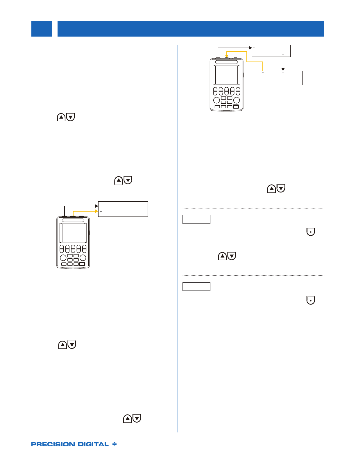
Voltage, Active Current Output
① Connect the black wire to the common terminal,
connect the yellow wire to the output terminal
② Press [Signal]to toggle the signal type
③ Press to adjust the output value
④ Press [Output], the “source” will change from OFF
to ON and start the output function.
4-20 mA Output
①Choose 4-20 mA for signal type
② Press the opposite [Signal]. You can choose
4→8→12→16→20 or press to adjust
③ Press [Output] to open the output function
MEASURE
SIGNAL SIGNAL
RANGE RANGE
OUTPUT
PROGRAM
WAVEFORM
COLDEND
4
5
6
8
7
9
1 2 3
MEASURE
SIGNAL SIGNAL
RANGE RANGE
OUTPUT
PROGRAM
WAVEFORM
COLDEND
4
5
6
8
7
9
1 2 3
MEASURE
SIGNAL SIGNAL
RANGE RANGE
OUTPUT
PROGRAM
WAVEFORM
COLDEND
4
5
6
8
7
9
1 2 3
MEASURE
SIGNAL SIGNAL
RANGE RANGE
OUTPUT
PROGRAM
WAVEFORM
COLDEND
4
5
6
8
7
9
1 2 3
PLC or
Other Instrument
Figure 1: Output Active Current/Voltage
to the meter or PLC
RTD and Thermocouple Output
Note: On thermocouple, the output temperature is
minus the voltage value corresponding to the cold
junction temperature.
① Press [Signal]to select signal type. Choose from
K/E/J/T/R/B/S/N/RTD/Ω
② Press to set output value of temperature
③ Press [Output]to open the function
Passive Current Output
Active with DIP Switch setting
Passive current output can be used as a 2-wire
transmitter simulator for loop testing.
① Choose 4-20 mA for signal type
② Press the opposite [Signal]. You can choose
4→8→12→16→20 or press the to adjust
③ Press [Output]to open the output function
MEASURE
SIGNAL SIGNAL
RANGE RANGE
OUTPUT
PROGRAM
WAVEFORM
COLDEND
4
5
6
8
7
9
1 2 3
MEASURE
SIGNAL SIGNAL
RANGE RANGE
OUTPUT
PROGRAM
WAVEFORM
COLDEND
4
5
6
8
7
9
1 2 3
MEASURE
SIGNAL SIGNAL
RANGE RANGE
OUTPUT
PROGRAM
WAVEFORM
COLDEND
4
5
6
8
7
9
1 2 3
MEASURE
SIGNAL SIGNAL
RANGE RANGE
OUTPUT
PROGRAM
WAVEFORM
COLDEND
4
5
6
8
7
9
1 2 3
24V Power
PLC or Other Instrument
Figure 2: 2-wire Transmitter Simulator
Voltage, Current Signal Output or
Measurement by Display Range
(Eliminates range conversions)
①Signal type must be voltage or current
② Press [Range]to select display range limit:
RL, RH, SL, SH
③ When “RL” is selected press to set value
④ Setup the RL, RH, SL, SH in turn
MEASURE
SIGNAL SIGNAL
RANGE RANGE
OUTPUT
PROGRAM
WAVEFORM
COLDEND
4
5
6
8
7
9
1 2 3
MEASURE
SIGNAL SIGNAL
RANGE RANGE
OUTPUT
PROGRAM
WAVEFORM
COLDEND
4
5
6
8
7
9
1 2 3
⑤ Press [Range]to exit the rage setup. Press to
toggle between signal output or range output
(no units are displayed on output)
⑥ Press the to change the output value
⑦Press [Range]to open the function
OUTPUT
MEASURE
MEASURE
SIGNAL SIGNAL
RANGE RANGE
OUTPUT
PROGRAM
WAVEFORM
COLDEND
4
5
6
8
7
9
1 2 3
⑤Press [Range]to exit the rage setup. Press to
toggle between signal value or range output
(no units are displayed on output)
⑥ It shows the measurement or conversion value
according to range
MEASURE
SIGNAL SIGNAL
RANGE RANGE
OUTPUT
PROGRAM
WAVEFORM
COLDEND
4
5
6
8
7
9
1 2 3
MEASURE
SIGNAL SIGNAL
RANGE RANGE
OUTPUT
PROGRAM
WAVEFORM
COLDEND
4
5
6
8
7
9
1 2 3
MEASURE
SIGNAL SIGNAL
RANGE RANGE
OUTPUT
PROGRAM
WAVEFORM
COLDEND
4
5
6
8
7
9
1 2 3
5www.predig.com
PD9501 Multi-Function Calibrator
SIGNAL MEASUREMENT
The calibrator can measure voltage, active current,
passive current, thermocouple signal, and RTD.
When measure function is not in use press [Measure]
to turn o the measure mode to conserve battery power.
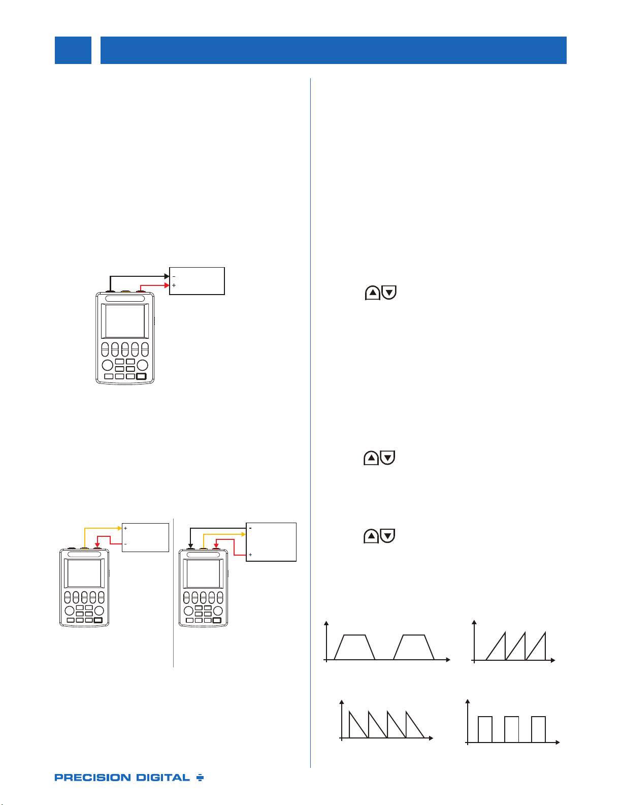
Voltage, Active Current Measurement
① Connect the black wire to the common terminal,
connect the red wire to the measure terminal
② Press [Measure]to open measure function
③ Press [Signal]to toggle signal type
④Shows value in the LCD screen
Instrument
Figure 3: Measurement voltage, active current
Passive Current Measurement
①Wiring as the 2-wire or 3-wire system
② Press Blue [Signal]to set signal type to 24 V loop
③ Generator outputs 24 V (or 16 V when via DIP
switch to low power mode
④ Shows value in the LCD screen
Transmitter
Transmitter
Figure 4:
Measure 2-wire transmitter
Figure 5:
Measure 3-wire transmitter
To view or adjust cold junction temperature for
thermocouple:
① Press [Cold End] to display cold end temperature
② If the LCD displays “RJA” the cold end is collected
by the internal sensor and cannot be modied.
③ Select the “M” on the LCD to manually set the
cold end value.
PROGRAMMABLE OUTPUT
Scaled Output Function (n/m)
The voltage, current, and thermocouple signals can be
scaled by n/m.
Output value = (Main Set Value) × (n/m)
①Press to change the main setpoint
② Press [Program] to open split output mode to
display n/m menu
③ Set (m) from 1 to 20
④ Set (n) from 0 to 20
⑤ Press yellow [Output]to open/exit the output
⑥ Press [Program] to exit the split output function
Linear Output Function
The signal value can be output linearly according to the
time set by the user.
① Press to set value for the main set point
② Press [Waveform] to display “sweep”. This enables
linear output function.
③ Press [Program] to set output time for rise time,
hold time [top], fall time, hold time [low].
Press to set time between 0-999s.
④ Press [Program] again to set number of linear
outputs from 0-999.
⑤ Press yellow [Output]to open/exit the output
⑥ Press [Program] to exit the linear output function
MEASURE
SIGNAL SIGNAL
RANGE RANGE
OUTPUT
PROGRAM
WAVEFORM
COLDEND
4
5
6
8
7
9
1 2 3
MEASURE
SIGNAL SIGNAL
RANGE RANGE
OUTPUT
PROGRAM
WAVEFORM
COLDEND
4
5
6
8
7
9
1 2 3
MEASURE
SIGNAL SIGNAL
RANGE RANGE
OUTPUT
PROGRAM
WAVEFORM
COLDEND
4
5
6
8
7
9
1 2 3
MEASURE
SIGNAL SIGNAL
RANGE RANGE
OUTPUT
PROGRAM
WAVEFORM
COLDEND
4
5
6
8
7
9
1 2 3
MEASURE
SIGNAL SIGNAL
RANGE RANGE
OUTPUT
PROGRAM
WAVEFORM
COLDEND
4
5
6
8
7
9
1 2 3
MEASURE
SIGNAL SIGNAL
RANGE RANGE
OUTPUT
PROGRAM
WAVEFORM
COLDEND
4
5
6
8
7
9
1 2 3
t1
t2
t3 t1
t4
t2
t3
T
t1 t1 t1
T
t3 t3 t3 t3
T
T
t2 t2 t2
t4 t4
Line out wave 1
Normal ming Line out wave 2
t2=t3=t4=0s
Line out wave 3
t1=t2=t4=0s Line out wave 4
t1=t3=0s
RTD and Thermocouple Measurement
①Connect the black wire to the common terminal,
connect the red wire to the measuring terminal
② Press blue [Measure] to set signal type to
K/E/J/T/R/B/S/N/RTD/Ω
③ Value is displayed on the LCD screen

LDS9501_A 03/19
PD9501 Multi-Function Calibrator
PRECISION DIGITAL CORPORATION
233 South Street • Hopkinton MA 01748 USA • Tel (800) 343-1001
www.predig.com
Disclaimer
The information contained in this document is subject to change without notice. Precision
Digital Corporation makes no representations or warranties with respect to the contents
hereof, and specically disclaims any implied warranties of merchantability or tness for a
particular purpose.
©2019 Precision Digital Corporation. All rights reserved.
Your Local Distributor is:
WARNING
Cancer and Reproductive Harm - www.P65Warnings.ca.gov
ORDERING INFORMATION
Model Description
PD9501 Multi-Function Calibrator
Automatic Step Output Function
The signal value can be stepped out according to the
user-dened value.
①Press to set value for the main setpoint
②Press [Waveform] to display “step”. This enables
step output function.
③ Press [Program] to set “time”. Press to set
time between 0-999s.
④ Press [Program] again to set N/m for step output
⑤ Press yellow [Output]to open/exit the output
⑥Press [Program] to exit the step output function
n
T
3
n-1 n-1
3
2 2
1 1
n
Step out wave
MEASURE
SIGNAL SIGNAL
RANGE RANGE
OUTPUT
PROGRAM
WAVEFORM
COLDEND
4
5
6
8
7
9
1 2 3
MEASURE
SIGNAL SIGNAL
RANGE RANGE
OUTPUT
PROGRAM
WAVEFORM
COLDEND
4
5
6
8
7
9
1 2 3
MEASURE
SIGNAL SIGNAL
RANGE RANGE
OUTPUT
PROGRAM
WAVEFORM
COLDEND
4
5
6
8
7
9
1 2 3
MEASURE
SIGNAL SIGNAL
RANGE RANGE
OUTPUT
PROGRAM
WAVEFORM
COLDEND
4
5
6
8
7
9
1 2 3
SPECIFICATIONS
Operating Temperature: 15 to 130°F (-10 to 55°C)
Storage Temperature: 5 to 158°F (-20 to 70°C)
Relative Humidity: 20 to 80%
External Dimensions: 4.5" x 2.5" x 10.2"
(115 mm x 70 mm x 26 mm)
Weight: 10.6 oz (300 g)
Power: Internal rechargeable Lithium Ion battery
(non-replaceable) or external USB power
Power Dissipation: 300 mA, 7-10 hours
Reverse Connection and Overcurrent Protection: 30 V
Cables Provided: Three signal cables and one USB
cable
Table of contents


