BMC Controls AQS610-EU-SF Quick start guide

AQS610-EU/SF (V2 H/W)
DOC 584 Issue A TECHNICAL GUIDE Page 1
AQS610-EU-SF
COPYRIGHT
Copyright 2006 BMC Controls Ltd. All rights reserved. No part of this publication may be reproduced, or
distributed without prior written permission of BMC Controls Ltd., The Factory, Silk Mill Lane, Winchcombe,
Gloucestershire, GL54 5HZ.
The majority of equipment designed and manufactured by BMC Controls Ltd is protected by patents and
industrial design copyright.
Examples of this include our PLASMA leak testing technique, stepper motor and adaptive control of conveyor
movement, box inverting devices, all software, electrical and pneumatic circuits.
SIX HEAD LEAKTESTER WITH SCREW FEED
TECHNICAL GUIDE
ISSUE A
Address: BMC Controls Ltd
The Factory
Silk Mill Lane
Winchcombe
Gloucestershire
GL54 5HZ
ENGLAND
Tel: (0)1242 604040
Fax: (0)1242 603987

AQS610-EU/SF (V2 H/W)
DOC 584 Issue A TECHNICAL GUIDE Page 2
Contents
1. GENERAL DESCRIPTION.........................................................................................................................................3
1.1 LEAKTEST STATION ..................................................................................................................................................3
2. PRINCIPLES OF OPERATION .................................................................................................................................4
2.1 LEAK TEST CYCLE ....................................................................................................................................................4
2.2 PURGE FUNCTION.....................................................................................................................................................4
2.3 REJECT BLOWER ......................................................................................................................................................5
2.4 SYSTEM LAYOUT DRAWING ......................................................................................................................................6
3. SET-UP PROCEDURE.................................................................................................................................................7
3.1 AQS SETTINGS.........................................................................................................................................................7
3.2 PROXIMITY SENSOR .................................................................................................................................................7
3.3 TOUCH-SET PHOTOSWITCHES...................................................................................................................................8
3.4 LEAK DETECTOR SET-UP..........................................................................................................................................9
3.5 REJECT STATION SET-UP.........................................................................................................................................11
3.6 JAM DETECTION SET-UP (OPTIONAL ) .....................................................................................................................11
4. OPERATOR CONTROL PANEL.............................................................................................................................12
4.1 LIQUID CRYSTAL DISPLAY......................................................................................................................................12
4.2 KEYPAD .................................................................................................................................................................12
4.3 PAGE SELECT KEYS................................................................................................................................................12
4.4 CURSOR KEYS.........................................................................................................................................................12
5. DISPLAY PAGES.......................................................................................................................................................13
5.1 PARAMETERS .........................................................................................................................................................13
5.1.1 Test Information ............................................................................................................................................13
5.1.2 Test Parameters.............................................................................................................................................14
5.2 FUNCTIONS.............................................................................................................................................................15
5.2.1 I/O Forcing....................................................................................................................................................15
5.3 SETTINGS................................................................................................................................................................17
6. THE LVD2 MOTOR DRIVER / CONTROLLER...................................................................................................18
6.1 LVD2 ERROR CODES.............................................................................................................................................18
6.2 ALTERING PARAMETERS ........................................................................................................................................18
6.3 SAVING PARAMETERS ............................................................................................................................................18
6.4 USER PARAMETERS................................................................................................................................................19
7. TROUBLESHOOTING..............................................................................................................................................20
7.1 INCONSISTENT LEAKTEST RESULTS.........................................................................................................................20
7.2 FAILURE TO REJECT BAD BOTTLES..........................................................................................................................20
7.3 BOTTLES NOT FILLING.............................................................................................................................................20
7.4 REJECTS GOOD BOTTLES.........................................................................................................................................21
7.5 SCREW FAULTS ......................................................................................................................................................21
8. I/O LIST.......................................................................................................................................................................22
8.1 AQS I/O INFORMATION..........................................................................................................................................22
8.2 LVD DRIVE I/O INFORMATION...............................................................................................................................23
9. EMERGENCY STOP.................................................................................................................................................24
10. CONTROL PANEL CONNECTIONS..................................................................................................................25
11. PARTS LIST............................................................................................................................................................26

AQS610-EU/SF (V2 H/W)
DOC 584 Issue A TECHNICAL GUIDE Page 3
1. General Description
The AQS610-EU-SF is a new high speed leaktesting system designed to leaktest containers up to 10L capacity.
It features a six head leaktester with an infeed / outfeed screw driven from a stepper motor.
Failed containers are rejected as they leave the screw.
If the unit is for the U.K and European market, it uses mB as its pressure measurement unit, the version for the
USA uses Psi.
1.1 Leaktest station
The standard leaktester is capable of testing bottles between 15 and 45 mB ( 0.2 - 0.8 Psi ), settable by the
user, all timers and delays are user settable enabling the machine to be run as quickly and accurately as each
individual job dictates.
Higher test pressures are available but this must be requested at the ordering stage.

AQS610-EU/SF (V2 H/W)
DOC 584 Issue A TECHNICAL GUIDE Page 4
2. Principles of operation
On start-up, the position of the infeed / outfeed screw is checked, regardless of whether the screw is in the
correct start position or not, the screw is slowly rotated ( at approx. 10 RPM ) until the home position is found ( a
proximity sensor detects a metal insert in the screw body ), while this process is ongoing a status message
‘HOMING SCREW’ is displayed, once the correct start position has been found, the status message changes to
‘SCREW READY’.
If the screw home position has not been found within the user set ‘Homing Timeout’ time, the status message
will display ‘SCREW ERROR’ and the Alarm will activate to alert the operator.
The unit should be powered down and the problem attended to before trying to operate the leaktester again.
The leaktester can be set up to only operate when a full load of bottles ( 6 ) are present or when at least one
bottle is present by altering the setting of the Start Photocell at either 6 or 1 bottles widths upstream from the
screw.
2.1 Leak test cycle
1. A bottle comes to rest in front of the Start photocell, when the Start Photocell has been triggered
constantly for a time set by the user ‘Start Time’ the test sequence begins.
2. The screw is instructed to rotate through 6 complete rotations to bring in the bottle for the next test and
expel the tested bottles.
3. As the screw turns, the home position proximity sensor should be seen to be clear to ensure that rotation
has started, and then be seen to made constantly for 50 ms to ensure rotation is complete, if this does
not happen within a time set by the operator ‘Screw Timeout’ then the test procedure will proceed as
normal, but the Alarm will operate to alert the operator and the error message ‘SCREW ERROR’ will be
displayed.
4. After a delay set by the operator ‘Head Delay’ the Test head cylinders are extended, this can be set to
zero if no delay is required.
5. The Fill valves are turned on.
6. The Fill valves turned individually off when ‘Test Pressure’ reached or ‘Fill Time’ expires.
7. If ‘Fill Time’ expires before ‘Test Pressure’ is reached, the result is returned as a failure. *
8. After a brief settling delay the initial pressure measurements recorded.
9. Pressure decay occurs over ‘Test Time’.
10. The final pressure measurements are recorded.
11. For each channel the ‘Retained Pressure %’ is calculated as the percentage of the initial pressure
measurement remaining when the final pressure measurement is taken.
12. If the ‘Retained Pressure %’ is less than the ‘Minimum Final Pressure%’ setting, the result is returned as
a failure, else the result is a pass. **
13. Test head cylinders retracted.
14. The unit will wait at this point until the ( optional ) Jam detection photocell is clear, in the event of an
upstream jam, the Alarm will operate and the an error message ‘HOLDING’ is displayed.
15. The sequence pauses at this point until the condition described at step 1 is met. ( see Purge Function )
* There are other conditions under which a bottle can fail the leaktest - these are described later in the manual.
** There are other conditions under which a bottle can fail the leaktest – these are described later in the manual.
2.2 Purge Function
In the event of bottles being left in the screw at the end of a product run or in the case of a machine breakdown,
there is an additional setting for ‘Purge Time’, if this time expires and another bottle ( or set of bottles ) have not
been detected to start another cycle, the screw will operate to drive the tested bottles through the reject station (
another test will be carried out after the screw operation in case 1 or more bottles ‘sneak’ in during the screw
operation ). If this feature is not required then the ‘Purge Time’ can be set to 0 to disable it.

AQS610-EU/SF (V2 H/W)
DOC 584 Issue A TECHNICAL GUIDE Page 5
2.3 Reject Blower
During the homing of the screw and the first in-screw of bottles at power up, the reject blower will activate to
reject any bottles which may have been left in the screw at previous power down, as these bottles will be of
unknown status.
IMPORTANT NOTE: - To achieve a reliable and repeatable reject sequence, the bottles are rejected from
the final screw position, whilst still on the deadplate, BEFORE they are allowed onto the conveyor as
the ‘drag’ at take-out cannot be relied upon to deliver each bottle at the exact same rate, hence the
reject timing becomes invalid.
1. The Reject Sequence is initiated as the screw starts to turn to bring the next set of bottles into the tester.
2. There is a settable delay ‘Reject Delay’ which elapses before the reject routine proper starts, to ensure that
bottle 1 has reached the reject blower position.
3. If bottle 1 test result is a fail the blower is turned on.
4. A delay ‘Reject On Time’ occurs, to ensure that the blower activates for long enough to remove a failed
bottle from the conveyor.
5. The reject blower is turned off ( if active ).
6. A delay ‘Reject Off Time’ occurs, to ensure that the leading edge of a good bottle following a failure is not
caught by the reject blow.
7. Steps 3 – 6 are repeated for all 6 leaktest positions.
NOTE : Because there is no method to differentiate between an Underfilled bottle, and an ‘empty’ test position,
the reject blower will still act for underfills, but they are NOT added to the failed bottle count.

AQS610-EU/SF (V2 H/W)
DOC 584 Issue A TECHNICAL GUIDE Page 6
2.4 System layout drawing
NOTE: The reject position is the last position where the bottle is still held in position by the screw.
Bottle indexing screw
Test heads
Dead plate
Direction
Of Travel
Start
P/S
Leaktest
Reject
Blower
Jam
Detection
P/S
Reject
Bin
6
5
4
3
2
1
R

AQS610-EU/SF (V2 H/W)
DOC 584 Issue A TECHNICAL GUIDE Page 7
3. Set-up Procedure
3.1 AQS Settings
Initially, set the unit with the following parameters:
Start Time 1.0 second
Head Delay 1.0 second
Fill Time 3.0 seconds
Test Time 3.0 seconds
TestPress 30 mB
Reject Delay 0.17 seconds
Reject On Time 0.10 seconds
Reject Off Time 0.06 seconds
Bottle Size ( set for the bottle to be tested )
Screw Timeout 1.50 seconds
MinFinal P% ( 1 – 6 ) 75%
Homing Timeout 7.0 seconds
Purge Time 0.0 seconds
The values for Reject Delay, Reject On Time & Reject Off Time were determined from tests done on the unit
before it left our factory, although they might not be exactly correct to run in a production environment, they will
at least provide a good starting point from which to set the unit correctly.
Set the CLAMP PRESSURE regulator to 30 psi.
Initially set the FILL RATE regulators to zero.
Initially fully restrict the Reject Blower.
Adjust the guide rails so that bottles travel centrally down the conveyor.
3.2 Proximity Sensor
The screw home position detection sensor is a Telemecanique inductive proximity sensor, there is no method of
adjusting the sensitivity of the sensor, it has a detection range of 1.6mm.
The position of the sensor is fixed, but there is adjustment for how near to the face of the bottle screw the
sensor can be position, when adjusting this sensor it should be position such that the gap between the sensing
face and the screw face should be 1mm. With power to the unit off, the screw should be rotated by hand such
that the implant in the screw is lined up with the sensor, the sensor distance should then be set and the sensor
secured firmly.
When the sensor is firmly secured, rotate the screw by hand through one full rotation ensuring that at no point
during the rotation does the screw make contact with the sensor ( a minimum gap of 0.5 mm should be
maintained at all times ).

AQS610-EU/SF (V2 H/W)
DOC 584 Issue A TECHNICAL GUIDE Page 8
3.3 Touch-set Photoswitches
All photoswitches are Baumer touch-set background suppressed photoswitches. They have a range 20mm to
430mm when used with smooth opaque components, they should not need re-adjusting when the
component colour is changed. Clear or textured components will reduce the range of these photoswitches.
In extreme conditions, careful adjustment may be required.
To enable the photoswitch to be set-up, there is a single push button and 2 LED’s. To push the button a blunt
object is required (e.g. a 3mm Allen key).
Normally the machine is despatched with the photoswitches set to maximum sensitivity (i.e. maximum range).
To reduce their range (i.e. suppress the background , following the procedure below.
Change the detection range of a photoswitch
1. Press the button on the photoswitch for approx. 2 seconds, until the green signal LED starts to flash.
2. Place the container to be detected at its normal distance from the photoswitch.
3. Press the button once and release.
4. Present the photocell with a typical background object that is to be ignored ( e.g. hold a bottle behind the
far guide rail, in line with the sense path ).
5. Press the button once and release.
The photoswitch is now set to the optimum switchpoint. Note; if the photoswitch flashes its red LED at the end
of this set-up procedure, it is indicating that it could not detect a reliable change in light level and therefore it
has not changed its parameters.
If a reliable detection cannot be achieved this way, a dynamic teach mode is also available.
Dynamic photocell teaching
1. Press the button on the photoswitch for approx. 5 seconds, until the green signal LED’s flashing mode
changes from slow to fast.
2. Allow a few sample parts to travel down the conveyor past the photocell sense point.
3. The photocell will attempt to automatically sense it’s minimum and maximum detection points.
4. Press the button once and release to end the dynamic teach process.
Maximise the detection range of a photoswitch
1. Press the button on the photoswitch for approx. 2 seconds, until the green signal LED starts to flash.
2. Align the photoswitch so that no light is reflected back to the photoswitch.
3. Press the button once and release.
4. Press the button once and release.

AQS610-EU/SF (V2 H/W)
DOC 584 Issue A TECHNICAL GUIDE Page 9
3.4 Leak Detector Set-up
The regulators described in this section are labelled for ease of identification.
The start photoswitch position can be set at any point upstream from the leaktest screw, the height should be
such that it detects bottles at ‘body’ height, the start photoswitch works off a timer, when a bottle is detected as
stationary in front of the photoswitch for a set time the screw-in sequence begins.
The best bottle stability will be achieved if the screw is only started when a decent queue of bottles have built
up, to operate in this way the start photoswitch should be positioned approx. 10 bottle widths upstream from the
start of the screw. The downside of this method is that at the end of a production run bottles will be left queuing
upstream of the start photoswitch and the test sequence will not be started, the test sequenced can be started
manually by triggering the start photoswitch by hand, or automatically by using the ‘Purge’ function,
refer to 2.2 Purge Function.
If it is preferred to have the leaktester run even if there is only 1 bottle present, then the start photoswitch should
be positioned immediately upstream from the start of the screw.
With the unit powered down, rotate the screw by hand until the metal insert in the screw is exactly in-line with
the home position sensor.
Place a bottle in each of the 6 screw testing positions, noting that screw position 1 ( the bottle nearest the
outfeed end of the screw ) is actually the reject position, test position 1 is actually screw position 2,
move the test heads such that they are aligned with the centre of the necks of the bottles, the height should be
set such that there is a gap of approx. 10mm between the top of the bottle and the bottom of the test head
‘nozzle’.
It is crucial to achieving correct set-up that the test head cross member is level and exactly parallel with
the bottle conveyor.
Using the Forcing function, refer to 5.2.1 I/O Forcing, force the Clamp ( OP 1 ) on, adjust the Clamp Pressure
regulator to obtain the correct force on the test head cylinders, as a rough guide, the pressure should be such
that the test heads should be able to be lifted off the bottle necks by hand, using a moderate amount of force
( such as that required to lift a bag of sugar with one hand ). Force the Clamp OP back to NORMal.
Feed bottles through the system, adjusting the bottle handling as required. Check that the system as a whole
can handle a queue of bottles correctly. At this stage of the setting up, all bottles will fail the leaktest but not be
rejected as the reject blower is currently restricted off, if mechanical set-up is correct then the ‘Head Delay’
setting should be able to be reduced to 0.0s at this stage and bottles should still be handled correctly.
When the bottle handling is correct, start to turn up the Fill Pressure. The Fill Pressure is regulated by the FILL
RATE regulator ( common to all fill valves ) and an individual restrictor fitted to each fill valve, Initially set a FILL
RATE value of 2 Bar and fully close off each of the Fill Valve restrictors.
Each channel should be set in turn following this procedure, feeding bottles through the system, gradually adjust
the restrictor on fill valve 1 so as to obtain pressurisation to the required Test Pressure. The easiest way to do
this is to observe the “Pressure 1” reading on the Parameters display page whilst adjusting the restrictor, with a
Test Pressure of 30 mB ( 0.5 psi ) selected, the pressure displayed at the beginning of the test (after the Fill
valve has switched off ) should be equal to or slightly higher than the required Test Pressure i.e. 30 - 35 mB (
0.50 - 0.53 psi ) ( not above this, more than a 20 % overshoot may cause the bottle to be rejected as an
OVERfill ).
If at this stage bottles are being rejected as OVER, reduce the Fill restrictor.
If at this stage bottles are being rejected as UNDER, increase the Fill restrictor.
At this stage it is important to be sure that the correct fill regulator is being adjusted, for the appropriate leaktest
channel.
Pressure 1, Bargraph 1, Final pressure 1 and Fill regulator 1 all relate to bottle No. 1 ( the first one into the test
station) etc.
When Channel 1 fill has been correctly set, the procedure should be repeated for channels 2 – 6.
When correct pressurisation has been achieved for all channels the ‘Fill Time’ setting should be reduced to that
required to achieve the desired throughput ( in this case 0.35 seconds ).

AQS610-EU/SF (V2 H/W)
DOC 584 Issue A TECHNICAL GUIDE Page 10
Send bottles through the system, if at this point any channel is failing the leaktest as Underfill ‘U’, increase the
Fill Valve restrictor associated with that channel until correct pressurisation is achieved. ( adjust the restrictor in
¼ turn increments and re-check ).
When the bottle handling is correct, the leak detector can be "Fine tuned". Firstly, check that the neck seal is
reliable. This can be done by temporarily setting the Test Time to a large value, for example 30 seconds. The
‘Retained Pressure %’ parameter should be not less than 70% on each channel for a good seal.
Set the ‘Test Time’ back to the maximum value possible, that will provide the required throughput.
( in this case 0.90 seconds ).
The test pressure ‘Test Press’ is normally left set to 30 mB ( 0.5 Psi ). However, this can be adjusted if
necessary ( if there is a specified test pressure or if the bottle is being distorted ).
To set the Minimum acceptable final pressure ( pass / fail threshold ) for channel 1 send several good bottles
through the system, noting the ‘Final P% 1’ displayed on the Parameters page, which should all be above 85%,
and consistent to within +/- 2%. Set the “MinFinal P% 1” to 2% below the lowest value measured.
Repeat this procedure for channels 2 - 6, referring to ‘Final P% 2’ and “MinFinal P% 2” for channel 2 etc.
At this point the leaktester should be finding leaking bottles ( although they will still not be rejected ) try inserting
a known leaking bottle into a flow of good bottles sever al times such that it gets tested in all of the test
positions, ensure that the bottle is correctly identified as a failure by the display relating to the channel in which it
was tested.

AQS610-EU/SF (V2 H/W)
DOC 584 Issue A TECHNICAL GUIDE Page 11
3.5 Reject station set-up
Because of the high speed nature of the throughput on this kind of tester, the Reject routine is complex
and can be tricky to set-up correctly, it is important that this part of the set-up procedure is followed
particularly carefully.
The reject blower is mounted at the outfeed end of the screw such that as a bottle is in the reject position it is
still just held within the screw and the bottle following it is directly positioned under test head 1.
For this part of the set-up you will require 6 good known bottles and 1 known leaking bottle, because it can be
tricky to monitor all parts of the tester at he same time, I recommend marking the six good bottles with numbers
1 to 6, feed the bottles through the tester in order 1 to 6 replacing the appropriate bottle in the stream with the
known leaking bottle as instructed. Using this method you will be able to tell easily if the correct bottle has been
rejected or the one proceeding or following has been rejected instead.
Start with the settings recommended is section 3.1 AQS Settings, i.e. ‘Reject Delay’ – 0.17 seconds,
‘Reject On Time’ – 0.10 seconds and ‘Reject Off Time’ 0.06 seconds.
The reject blower restrictor should be fully unwound.
Send six bottles through the tester, the first one in being the leaking bottle and the following 5 being known
good bottles, observe the action of the reject station.
If the blower activates before the leaking bottle is positioned in front of it, increase ‘Reject Delay’, if the blower
activates late on the bottle, or after it has passed, decrease ‘Reject Delay’.
NOTE: When optimising the reject station settings, very small changes should be made between tests
( i.e. not more than 0.02 seconds per change )
Repeat this procedure until clean and repeatable rejection of bottle 1 has been achieved.
When the timing of the reject blow has been correctly set, the duration of the reject blow ‘Reject On Time’
should be optimised, it should be set to the shortest possible time which will give clean repeatable bottle
rejection.
Once optimum values have been achieved for ‘Reject Delay’ and ‘Reject On Time’, move the leaking bottle to
position 2 and feed the bottles through the tester, observe the action of the reject station.
If the blower activates before the leaking bottle is positioned in front of it, increase ‘Reject Off Time’, if the
blower activates late on the bottle, or after it has passed, decrease ‘Reject Off Time’.
Repeat this procedure until clean and repeatable rejection of bottle 2 has been achieved.
The test should now be repeated with the leaking bottle in positions 3 – 6, ensure that the bottle is correctly
identified and rejected in all possible positions, if any adjustment is required then ‘Reject Off Time’ should
tweaked rather than either of the other reject settings. Adjustments of +/- 0.01 seconds should be made and the
unit re-tested until the optimum value has been found for this setting.
3.6 Jam detection set-up ( optional )
The Jam detection photocell should be positioned at least 7 bottles downstream form the end of the leaktester
screw, and set to body height. This will ensure that bottles will not be expelled from the screw unless there is
room on the outfeed conveyor for them to be fed into ( the reason for 7 rather than 6 is to ensure that the last
bottle out of the screw does not come to rest in front of the reject blower ).
AQS610-EU/SF (V2 H/W)
DOC 584 Issue A TECHNICAL GUIDE Page 12
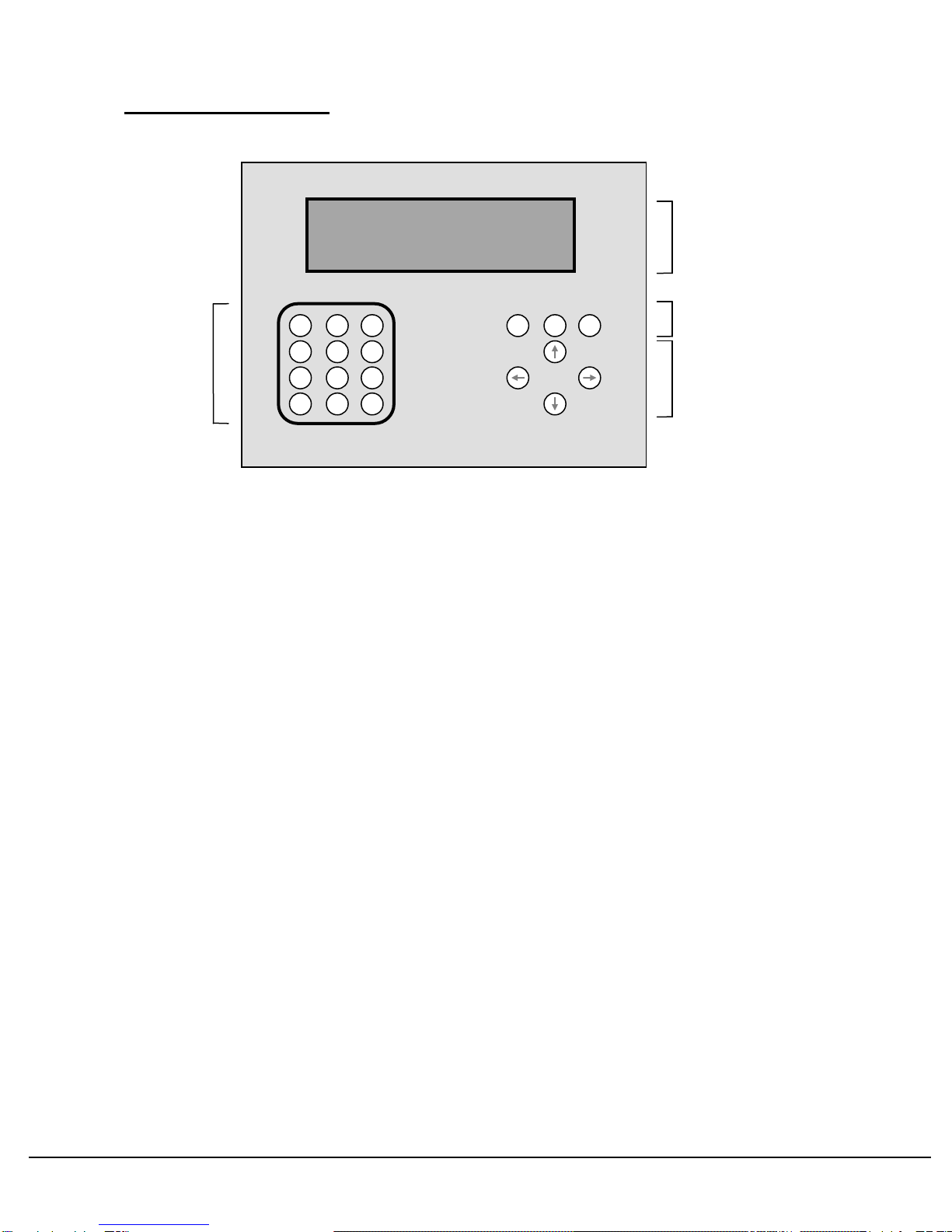
4. Operator Control Panel
4.1 Liquid Crystal Display
Used to display information. Allows a visual indication of test results and settings in the form of various pages.
Each page can display up to 4 items regarding a particular mode. Visual indication is given in the top left corner
of the display when a key is pressed.
NOTE: This unit Features an ‘UN-SAVED DATA ALERT’, whenever a system parameter ( e.g. count etc. ) or a
system setting’s value is altered, ‘!’ is displayed in the top right hand corner of the display, care should be taken
not to switch the unit off whilst this warning is displayed, otherwise data may not be stored correctly.
NOTE: The LCD display is back-lit to improve visibility, this backlight facility has an auto-power down
feature to conserve power and extend the life of the LCD display. At power up the LCD backlight is
illuminated and will remain so for 5 minutes, any subsequent keypress will re-start this 5 minute
countdown. When the backlight is not illuminated pressing any key on the AQS keypad will cause the
back light to illuminate again and the 5 minute countdown to re-start.
4.2 Keypad
Consists of the number keys 0-9, decimal point key and enter key ‘E’. Used to change pages and settings.
4.3 Page Select Keys
Used to select display mode. Three basic modes exist - Parameters, Functions and Settings. Parameters
show test results and measurements. Functions allow the various program-specific functions to be changed
and the forcing of I/O states. Settings allows the changing of the test settings.
4.4 Cursor keys
Consists of up, down, left and right keys used to move between the various items on a page. The up/down
keys change between selected items on the page which will switch to the next page in the sequence if more
than there are more than 4 items. In Settings mode the right/left keys increase/decrease the setting by a fixed
amount, and allow the cursor position to be moved when editing settings to correct wrongly entered values.
KEYPAD
9
8
7
6
5
4
3
2
1
E
0
.
SETTINGS
FUNCTIONS
PARAMETE
CURSOR KEYS
LIQUID CRYSTAL
DISPLAY
PAGE SELECT
KEYS

AQS610-EU/SF (V2 H/W)
DOC 584 Issue A TECHNICAL GUIDE Page 13
5. Display Pages
5.1 Parameters
5.1.1 Test Information
On the right hand side of the parameter display page can be seen the Bargraph pressure displays and the test
status “flashes”, the bargraph displays will rise as pressure in the containers rises, the top of the bargraph,
100% is equal to the Test pressure set by the user.
The status “flash” displays the state of the current / previous test, the flash appears above the bargraph of the
channel to which it relates, the following options may be seen.
“ T ” The container under test is undergoing pressure decay test
“ P “ The previous container passed the leaktest
“ F “ The previous container failed the leaktest
“ G “ The previous container failed the leaktest as a gross leaker
“ U “ The previous container failed the leaktest as under pressure, i.e. test pressure was not
reached, either the container has a very large hole or some system adjustment is
required, see - troubleshooting. ( or no bottle was present in that test position )
“ O “ The previous container failed the leaktest as over pressure, some system adjustment
is
required, see - troubleshooting.
There are also several warning / information / error messages which can also appear in this position, the
following options may be seen.
“ HOMING SCREW “ At initial power-up, the position of the bottle screw is checked, if the screw is not in the
correct position to begin testing, then a homing routine is carried out to bring the screw
to the correct position, this message is displayed during that sequence.
“ SCREW ERROR “ If the user set ‘Homing Timeout’ timer expires before the screw is seen to have
reached the home position, or the user set ‘Screw Timeout’ timer expires before the
screw has been seen to complete a 6 revolution sequence then this error message is
displayed.
“ SCREW READY “ When screw homing is completed successfully at power-up, this message is displayed
to show that the unit is ready to begin testing.
“ HOLDING “ The current test cycle is complete but bottles are being held in the test station because
the optional downstream jam detect photocell is blocked.

AQS610-EU/SF (V2 H/W)
DOC 584 Issue A TECHNICAL GUIDE Page 14
5.1.2 Test Parameters
On the left hand side of the display values such as passed and failed counts and measured pressure readings
are displayed. The values can be zeroed by pressing the ‘0’ key when the parameter to be zeroed is selected.
For this program the following parameters may be seen:
1. Pressure 1 - “LIVE” pressure reading for channel 1.
2. Final P % 1 - Final pressure % of the last bottle leak tested in channel 1.
3. Pressure 2 - “LIVE” pressure reading for channel 2.
4. Final P % 2 - Final pressure % of the last bottle leak tested in channel 2.
5. Pressure 3 - “LIVE” pressure reading for channel 3.
6. Final P % 3 - Final pressure % of the last bottle leak tested in channel 3.
7. Pressure 4 - “LIVE” pressure reading for channel 4.
8. Final P % 4 - Final pressure % of the last bottle leak tested in channel 4.
9. Pressure 5 - “LIVE” pressure reading for channel 5.
10.Final P % 5 - Final pressure % of the last bottle leak tested in channel 5.
11.Pressure 6 - “LIVE” pressure reading for channel 6.
12.Final P % 6 - Final pressure % of the last bottle leak tested in channel 6.
13.# Leak Pass - The number of containers to pass the leak test so far.
14.# Leak Fail - The number of containers to fail the leaktest so far.
15.Rej Count - Shows the ‘live’ count of the reject index, this parameter can be used as a rough
guide to ensure that the reject routine is indexing in time with the screw revolutions.
NOTE : The standard screen display has bargraph No. 1 on the far right of the display, depending on
the physical mounting of the operator panel, this may be the same as the physical layout of the
machine, or it may be the other way round, it can be confusing if the screen layout does not match
the physical layout, if the screen layout is the wrong way round it can be reversed by linking IP 7
‘REVERSE DISP’ to 24V on the Input Card in the Operator Panel.

AQS610-EU/SF (V2 H/W)
DOC 584 Issue A TECHNICAL GUIDE Page 15
5.2 Functions
This page features the I/O forcing function as well as any additional function which maybe specific to a
particular unit. For this program the following functions are present: I/O Forcing only.
5.2.1 I/O Forcing
The I/O Forcing feature allows the operator to view the current status of each of systems Inputs and Outputs
and also to manually override the system control and Individually force any Input or Output on or off. This is
useful as fault-finding tool - e.g. If a system is fitted with a photocell which when triggered starts a particular part
of the process and does not appear to be working, the operator can force the input associated with that
photocell on, if the process now functions correctly a faulty photocell can be assumed.
Each input our output can be in one of three states:
NORM: - The normal state as controlled by the system.
ON: - Forced on.
OFF:- Forced off.
Note: Towards the back of this manual is an I/O list, this can be used to identify which Input or Output
number is associated with which function.
The display will show the currently selected input or output, along with it’s forced status and it’s normal status.
Inputs and outputs are shown in groups of four, the one to be altered will be highlighted with the cursor arrows.
The I/O is displayed in the following order Outputs 1 - 16 then Inputs 1 - 8, the display will loop from the end
back to the beginning if required.
A typical display line will be as follows:
function number( cursor indicates function currently selected ) Normal status
3: > OP3 FORCED: ON < off
IP / OP number Forced status
The keys are used as follows:
UP / DOWN: Move the highlight cursor up or down respectively to select the desired input or output, in the
event that the top of the four displayed items is selected and the UP key is pressed or the bottom of the four
displayed items is selected and the DOWN key is pressed the display will update to previous or next
page respectively.
<: Force the currently selected input or output OFF, repeatedly pressing the “<“ key will cause the status to
alternate between OFF and NORM.
>: Force the currently selected input or output ON, repeatedly pressing the “>“ key will cause the status to
alternate between ON and NORM.
0: Return the currently selected input or output to it’s NORMal state.
.: ( decimal point ) - Return all inputs and outputs to there NORMal state.

AQS610-EU/SF (V2 H/W)
DOC 584 Issue A TECHNICAL GUIDE Page 16
Also displayed on this page, on the very bottom line of the display is an I/O Status map, this gives a visual
indication of the current status of all the system Inputs and Outputs.
Each Input and Output has a single digit display associated with it, there are four possible status’s for each
individual input or output
0 : The input / output is under normal machine control and is currently off.
1 : The input / output is under normal machine control and is currently on.
- : The input / output is currently forced off.
+ : The input / output is currently forced on.
The information in the I/O Status map is shown ( from left to right ) as Outputs 1 to 16, Inputs 1 to 8.
A typical I/O Status line may look as follows:
OP’s 1000101011001+1- IP’s 0010++10
Output 1 is normally on Input 5 is forced on
Output 6 is normally off Output 16 is forced off
IMPORTANT: After I/O forcing always ensure that all functions are set to NORM before attempting to
run the unit again.
This can be done by manually returning all input / outputs to NORM ( as described on the previous page ),
pressing the “.” key to force ALL input / outputs to NORM or switching power to the unit off then on again.
Pressing the PARAMETERS or SETTINGS keys will return the unit to Parameters or Settings display page
respectively.
If the unit has Password Protection or a Printer function page, pressing the FUNCTIONS key will alternate
between these pages and the Functions page.
IMPORTANT: After I/O forcing always ensure that all functions are set to NORM before attempting to run the
unit again, this can be done as described above or by switching unit power off and on again.

AQS610-EU/SF (V2 H/W)
DOC 584 Issue A TECHNICAL GUIDE Page 17
5.3 Settings
Display the various settings and allows them to be changed. By pressing the right/left keys, the setting value
will be increased/decreased by a fixed amount.
Pressing the ‘E’ key will allow the value to be entered directly with the keypad numbers. Wrongly entered
values can be changed by using the left/right keys to move the cursor to the digit to be changed. Pressing the
‘E’ key when the value has been entered will change the setting to the new value, providing that it is within the
pre-set value range for the setting to be changed.
For this program the following settings are present:
1. “Start Time” -Time for which a bottle must be present in front of the Start Photocell to trigger
a leaktest cycle start.
2. “Head Delay” - Delay between the end of screw rotation at bottle feed-in and the test head
cylinders extending on the bottles ( to allow the bottles to stabilise in the test
area ). Can be set to 0 if no delay is required.
3. “Fill Time” - Maximum time allowed for bottles to be pressurised to the set ‘Test
Pressure’.
4. “Test Time” - Time allowed for pressure decay leaktesting.
5. “Test Press” - Level to which the bottles are pressurised for leaktesting.
6. “Reject Delay” - Delay between the start of the screw rotation before the reject sequence
commences.
7. “Reject On Time “ - Time for which the Reject Blower activates to remove a failed bottle from the
container, this must be carefully set to match the screw revolution time.
8. “Reject Off Time” - Delay between the Reject Blower de-activating for the previous bottle before
it is energised for the following one.
9. “Bottle Size” - Should be set to the size of the bottle to be tested, for bottles over 1L leave
set to 1L.
10.“Screw Timeout” - Maximum time allotted for the bottle screw to travel through 6 full revolutions.
11.-16. “Min Final P % 1 - 6” - Level of final pressure % for leaktester which defines the reject
point, results lower than this are rejected. ( a setting per channel )
17.“Homing Timeout” - Maximum time allotted for the bottle screw to reach it’s homing position at
power-up.
18.“Purge Time” -Time for which the leaktester will wait for a bottle ( or set of bottles ) before
automatically activating to feed tested bottles through the reject station ( if set
to 0, this function is switched off )
19.”Enable Testing” - Set to 1 to enable normal leaktesting function, set to 0 to disable the leaktest
function and allow bottles to pass through the screw.
NOTE: When changing between different product runs it may be necessary to change some or all of the
settings to handle the new product. In the back of this manual you will find some blank settings record sheets,
when you have set the leaktester up for a particular product, you may wish to use these sheets to make a note
of the settings to refer back to next time that product is tested.

AQS610-EU/SF (V2 H/W)
DOC 584 Issue A TECHNICAL GUIDE Page 18
6. The LVD2 Motor Driver / Controller
The LVD2 driver is situated in the main pneumatic cabinet, it controls all aspects of the motor operation, it can
be used to vary certain parameters associated with the motor’s operation.
During normal operation the unit will display the current operating mode ( also known as Pr0 ), the two states for
Pr0 are:
Idle – The driver is currently performing no function because the enable input ( IP0 ) is not made.
Run – The drive is following it’s program sequence, IP0 is made.
6.1 LVD2 Error Codes
There are also certain error codes which may be displayed in the event of a fault condition, the codes, their
meanings and possible causes are:
Er. 01 – Over Voltage on DC Link, check the mains power supply to the LVD2 drive ( voltage must not exceed
253 VAC ).
Er. 02 – Under Voltage on DC Link, check the mains power supply to the LVD2 drive ( voltage must not be
lower than 130 VAC ).
Er. 03 – Over Current, check motor connections, pay particular attention to short circuits between phases or
phase to ground.
Er. 04 – Resolver Alarm, check the resolver connections at both ends of the cable.
Er. 06 – Drive Over Temperature, check the cooling fans and ensure that air-flow is not obstructed or restricted.
Check the internal temperature of the cabinet in which the LVD2 drive is installed and external ambient
temperature.
Er. 10 – PLC Checksum error, the PLC program in the LVD2 drive has become corrupted, contact BMC
Controls for a service visit.
Er. 11 – Parameter Checksum error, some or all of the system parameters have become corrupted, check and
re-enter the system parameters as described below, if this does not solve the problem contact BMC
Controls for a service visit.
6.2 Altering Parameters
The drive has three buttons used to alter system parameters (M) – mode button, (+) and (-) adjust buttons.
To alter the value associated with a certain parameter, use the + and – keys to navigate through the Parameter
list until the desired parameter is displayed. Press the M key to enter edit mode, Use the + and – keys to set the
desired value, when this is done press the M key again to return to normal mode.
In the event of nested parameters ( e.g. Pr99.14 ), use the + and – keys to navigate to the master parameter (
e.g. Pr99 ) press M, now use the + and – keys to navigate to the desired sub-parameter ( e.g. 99.14 ) press M,
you are now in edit mode and can use the + and – keys to set the desired value, pressing the M key again
returns to normal mode.
NOTE: Although all changes made take immediate effect to the running sequence, they will be lost at
power down unless saved, see below.
6.3 Saving Parameters
When changes have been made to Parameter values, they must be saved to the LVD’s memory or will be lost
when the unit is powered down.
To save Parameter changes use the + and – keys to navigate to master Parameter b99, press M. Now use the
+ and – keys to navigate to sub-parameter 99.15, press M. The display will read 0, press the + key, the display
will momentarily read “done” and then return to 0. The changes have now been saved and you may safely
power down the unit without losing changes.

AQS610-EU/SF (V2 H/W)
DOC 584 Issue A TECHNICAL GUIDE Page 19
6.4 User Parameters
NOTE: Through the LVD keypad you have full access to all system Parameters, DO NOT adjust any
parameters other than those show below as this may have a serious adverse affect on the operation of
the unit.
Pr01 Homing Speed & Direction, the speed is set RPM for the motor shaft, but the gearbox must be born in
mind, e.g. for this application I decided to run at 10 RPM, the motor has a 7-1 gearbox, ( 10 x 7 = 70 ) and to
make the motor run clockwise it is a positive value ( negative for anti-clockwise ).
If this value is altered then the screw will be slightly out of position at the start of testing, leave set to
70.
Pr 16 Integral Gain Speed Loop, ( should be set to 80 for this application ).
Pr17 Speed Control Loop Damping, ( should be set to 180 for this application ).
Pr26 Sets Baud Rate for serial communications, default is 6which equates to 19200.
Pr29 Sets the number of Motor Poles ( in this particular application should be set to 4).
b40.14 Enable Serial Communication, set to 1 to enable serial comms with laptop, 0 to disable.
This Parameter bit should always be set 1.
Pr51 Acceleration & Deceleration time for normal operation, in this application set to 0.1 seconds ( will be
displayed as 100 on the LVD2 drive display ).
Pr52 Motor Speed for normal operation, the speed is set RPM for the motor shaft, but the gearbox must be
born in mind, e.g. for this application we want to get 6 revolutions in as quick a time as possible, the optimum
value for this parameter was found by experimentation, e.g. the speed was increased until the optimum value
was found which gave the highest speed yet maintained smooth operation, this was found to be 2250 to convert
this to an actual speed it must be divided by the gearbox ration ( 2250 / 7 = approx. 320 RPM ) this equates to
5.33 revolutions per second giving a ‘Screw In’ time of 1.125 seconds for six bottles. *
Pr64 Distance of travel for normal operation, set in steps where one complete revolution of the motor shaft is
4096 steps, so for 6 revolutions, bearing the gearbox in mind ( 4096x6x7 = 172032 ).
NOTE: Because this value is longer than 1 ‘word’ the value when entered will ‘overlap’ into parameter
Pr65, this is normal.
b70.4 Direction of travel for normal operation, set to 1 or 0 as appropriate to set the desired direction of travel.
b99.6 Extended Parameter Access, setting this parameter bit to 1 gives the user full access to all system
parameters via the LVD2 Keypad.
b99.13 PLC Operation mode, sets the mode of operation of the on-board micro PLC, set to1 to run the
program, 0 to edit the program from the plug-in keypad ( highly un-recommended ).
This Parameter bit should always be set 1.
b99.15 Save Parameter Changes – If any Parameters been changed, then this bit must be set to save those
changes, after setting it will immediately reset itself automatically. See important notes on page 1 of this
document.
* The overall cycle time and bottle throughput for this unit is based around the screw speed noted above, if this
speed is altered than the unit cannot be guaranteed to operate at the required speed. Also the settings
associated with the reject feature – ‘Reject Delay’, ‘Reject On Time’ and ‘Reject Off Time’ will need to be
adjusted to keep the reject routine in synchronisation with the new motor speed, and a new appropriate value
for ‘Screw Timeout’ must be set.

AQS610-EU/SF (V2 H/W)
DOC 584 Issue A TECHNICAL GUIDE Page 20
7. Troubleshooting
7.1 Inconsistent leaktest results
Could be due to:
1. Bad neck sealing. Check that the screw is positioning bottles directly under test heads and that sealing pads
are undamaged.
2. Clamp pressure too low. Causes poor neck seal with bottle neck. Increase clamp pressure regulator
slightly.
3. Clamp pressure too high. Causes bottle necks to distort, releasing air pressure inside. Reduce clamp
pressure regulator slightly.
4. Leaking pneumatic fittings or pipes. Check that joints between fittings are airtight and pneumatic pipes are
not damaged.
5. Sense pipe blocked. Pressure readings will show a sluggish response to pressure changes. Check that
sense pipes from test heads to pressure transducers on main control board are not blocked/kinked,
especially when cabinet front panel is shut.
6. Fill time set too low. Bottle not reaching test pressure in allotted time. Increase fill time Setting.
7. Test pressure set too low. Bottle not being pressurised enough to expose very small holes. Increase test
pressure Setting.
8. Fill regulator set too low. Not enough air flow to fill the bottle to test pressure in allotted time. Increase Fill
regulator.
9. Test time too short. Not enough time allowed for a reliable Leaktest. Increase Test time Setting.
7.2 Failure to reject bad bottles
If the test results indicate that a bottle has been failed but was not rejected from the conveyor:
1. Check screw homing position sensor is operating correctly.
2. Check reject blower OK. Valve can be forced “ON” from the front panel by turning on the function
corresponding to the reject blower output to check the electronics and the valve solenoid. Manually turning
on the valve will check the valve operation. (See Functions section and I/O list and front panel controls for
details).
3. Check that the ‘Reject Time’ setting is et such that the operation time matches the time taken for one screw
revolution.
If the test results do not indicate that a bottle should have been failed:
1. Check the ‘Final P%’ for the bottle tested. Adjust the ‘Min Final P %’ setting if necessary to reject failures but
to pass good containers.
2. Check transducer is not damaged or that pneumatics are connected and intact.
3. Fill regulator set too high. Bottles are over pressurising. Reduce Fill regulator.
4. Test pressure too low. Sometimes a higher test pressure is necessary to expose smaller holes. Increase
‘Test Pressure’ setting.
5. Fill Time too low. Bottle not reaching test pressure in allotted time. Increase ‘Fill Time’ setting.
6. Test time too short. Not enough time allowed for a noticeable pressure drop in the bottle (for a small hole).
Increase ‘Test Time’ Setting.
7.3 Bottles not filling
Occasionally a bottle may not fill correctly if the neck seals and bottle do not line up for any reason, e.g. bottle
wobbling in test station too much .Other factors may cause the bottles not to fill on a regular basis:
1. Test head neck seal damaged. Replace faulty seal.
2. Test head bracket set too high. Cylinders do not reach bottles when extended. Lower test head bracket.
3. Clamp pressure set too high. Bottles distorted and not sealing on test seals. Lower clamp pressure
regulator.
4. Clamp pressure set too low. Head not making a good seal, air leaking around bottle neck. Increase clamp
pressure regulator.
5. Fill pressure too high. Lower test pressure (not below 15mB ( 0.15 psi )), increase fill valve pressure
regulator or increase ‘Fill Time’ setting.
Table of contents


