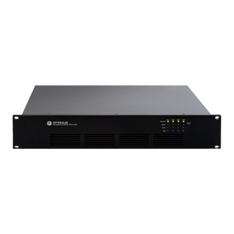
Precision MicroDynamics Polaris User manual

Polaris™ Amplifier Hardware Installation Manual
www.pmdi.com

ii
www.pmdi.com
Precision MicroDynamics Inc.
Polaris™Amplifier Hardware Installation Manual Version 1.2.5
© 2012 Precision MicroDynamics Inc. All rights reserved. This material may not be published, broadcast,
rewritten or redistributed.
Information provided by Precision MicroDynamics is believed to be accurate and reliable. However, Precision
MicroDynamics assumes no liability resulting from omissions in this document, or from the use of the information
obtained therein. This includes any infringement of patents or other rights of third parties that may result from its
use. No license is granted by implication under the patent rights of Precision MicroDynamics Inc. Precision
MicroDynamics reserves the right to revise the manual and the product it describes without notice. No part of this
document may be reproduced in any way, shape or form without prior permission from Precision MicroDynamics
Inc.
Contact Precision MicroDynamics at:
#3- 512 Frances Ave.
Victoria, BC, Canada, V8Z 1A1
Toll free: 1 (866) 548-5639
Phone: 1 (250) 382-7249
Fax: 1 (250) 382-1830
WWW: www.pmdi.com
Revision History
Version 1.2.5 Updated for minor release May, 2012
Version 1.2 Updated diagrams/specifications February, 2012
Version 1.0 Updated for Polaris 1.0 October, 2011
Version 0.9 Major updates including specifics July 15, 2011
Version 0.8 Initial Release June 20, 2011

iii
www.pmdi.com
Disclaimer
Warning regarding medical and clinical use of PMDI products
Precision MicroDynamics’ (PMDI) products are not designed with components and testing intended to ensure the
level of reliability for use in the treatment and diagnosis of humans. Application of PMDI products involving
medical or clinical treatment can create a potential for accidental injury caused by product failure, or by errors on
the part of the application designer. Any use or application of PMDI products for or involving medical or clinical
treatment must be performed by properly trained and qualified medical personnel, and all traditional medical
safeguards, equipment, and procedures that are appropriate for the particular situation to prevent serious injury
or death should always continue to be employed when PMDI products are used. PMDI products are NOT intended
to be a substitute for any form of established process, procedure, or equipment used to monitor or safeguard
human health and safety in medical or clinical treatment.
Limited Warranty
The Polaris™amplifier hardware is warranted against defects in materials or workmanship, for a period of one (1)
year from the date of shipment as evidenced by receipts or other documentation. PMDI will, at its option, repair or
replace equipment that proves defective if PMDI receives notice of such defects during the warranty period. PMDI
does not warrant that the operation of the software shall be uninterrupted or error free. A return material
authorization (RMA) number must be obtained from the factory and clearly marked on the package before any
equipment will be accepted for warranty work.
PMDI believes that the information in this manual is accurate. This document has been carefully reviewed for
technical accuracy. In the event that technical or typographical errors exist, PMDI reserves the right to make
changes to subsequent editions without prior notice to holders of this edition. The reader should consult PMDI if
errors are suspected. In no event shall PMDI be liable for damages arising from or related to this document or the
information contained in it.
EXCEPT AS SPECIFIED HEREIN, PMDI MAKES NO WARRANTIES, EXPRESSED OR IMPLIED, AND SPECIFICALLY
DISCLAIMS ANY WARRANTY OF MERCHANTABILITY OR FITNESS FOR A PARTICULAR PURPOSE. THE CUSTOMER'S
RIGHT TO RECOVER DAMAGES CAUSED BY THE FAULT OR NEGLIGENCE ON THE PART OF PMDI SHALL BE LIMITED
TO THE AMOUNT THERETOFORE PAID BY THE CUSTOMER. PMDI WILL NOT BE LIABLE FOR DAMAGES RESULTING
FROM LOSS OF DATA, PROFITS, USE OF PRODUCTS, OR INCIDENTAL OR CONSEQUENTIAL DAMAGE, EVEN IF
ADVISED OF THE POSSIBILITY THEREOF.
The limitation of the liability of Precision MicroDynamics will apply regardless of the form of action whether in
contract or tort, including negligence. Any action against Precision MicroDynamics must be brought within one
year after the cause of action accrues. Precision MicroDynamics shall not be liable for any delay in performance
due to causes beyond its reasonable control. The warranty period herein does not cover damages, defects,
malfunctions, or service failures caused by the owner's failure to follow the Precision MicroDynamics installation,
operation, or maintenance instructions; owners modification of the product; owner's abuse, misuse, or negligent
acts; and power failure or surges, fire, flood, accidents, actions of third parties, or other events outside reasonable
control.
Copyright
Under the copyright laws, this publication may not be reproduced or transmitted in any form, electronic or
mechanical, including photocopying, recording, storing in an information retrieval system, in whole or in part,
without the consent of Precision MicroDynamics Incorporated.

iv
www.pmdi.com
Contents
Figures........................................................................................................................................................... v
Tables ........................................................................................................................................................... vi
Terms and Definitions.................................................................................................................................. vi
Chapter 1: Safety Information ...................................................................................................................... 1
1.1 Safety Symbols.............................................................................................................................. 1
1.2 Caution.......................................................................................................................................... 1
Chapter 2: Introduction ................................................................................................................................ 2
Chapter 3: Description .................................................................................................................................. 3
3.1 Specifications ................................................................................................................................ 4
Chapter 4: Connectors .................................................................................................................................. 6
4.1 Power Connector .......................................................................................................................... 6
4.2 Mercury™ Connectors................................................................................................................... 7
4.3 Encoder Feedback Connector ....................................................................................................... 8
4.4 Motor Connector ........................................................................................................................ 11
4.5 Motor Power Safety Connector ..................................................................................................13
4.6 Hall Sensor Connector................................................................................................................. 14
4.7 IO Connector ...............................................................................................................................15
Chapter 5: Mounting the Amplifier.............................................................................................................16
Chapter 6: Connecting Cables..................................................................................................................... 17
6.1 24V Power Supply ....................................................................................................................... 17
6.2 Mercury™ Connection ................................................................................................................18
6.3 Encoder Feedback Connection ................................................................................................... 19
6.4 Motor Connection....................................................................................................................... 23
6.5 Motor Safety Connection............................................................................................................ 25
6.6 Hall Sensor Connection............................................................................................................... 26
6.7 Digital IO...................................................................................................................................... 27
Chapter 7: Power Up................................................................................................................................... 30
7.1 Powered State............................................................................................................................. 30
7.2 Diagnostic LEDs ........................................................................................................................... 30
Chapter 8: Conclusion................................................................................................................................. 32
Appendix A: Dimensions ............................................................................................................................. 33

v
www.pmdi.com
Appendix B: Specification Chart..................................................................................................................34
Appendix C: Sony Scale Interface................................................................................................................ 35
Appendix D: Renishaw Cable ......................................................................................................................38
Figures
Figure 1: Amplifier Overview ........................................................................................................................ 2
Figure 2: Mercury™ Connection ................................................................................................................... 7
Figure 3: Mounting the Polaris™ Amplifier................................................................................................. 16
Figure 4: 24V Power Supply Suggested Wiring........................................................................................... 17
Figure 5: Typical Mercury Network.............................................................................................................18
Figure 6: Sin Cos Encoder Terminations .....................................................................................................19
Figure 7: Resolute™ or Serial BiSS® Encoder Terminations ........................................................................ 20
Figure 8: A Quad B Single Ended Encoder Terminations ............................................................................21
Figure 9: A Quad B Differential Ended Encoder Terminations....................................................................22
Figure 10: 3 Phase Motor Connection Suggested Wiring ........................................................................... 23
Figure 11: Single Phase Motor Connection Suggested Wiring ................................................................... 24
Figure 12: Bleeder Resistor Connection......................................................................................................25
Figure 13: Motor Brake Relay Connection .................................................................................................25
Figure 14: Hall Sensor Connections ............................................................................................................26
Figure 15 : Digital IO Connection ................................................................................................................29
Figure 16 : High Speed Digital IO Connection ............................................................................................. 30
Figure 17: Diagnostic LEDs .......................................................................................................................... 31

vi
www.pmdi.com
Tables
Table 1: Power Connection........................................................................................................................... 6
Table 2: Sin Cos Encoder Feedback Connection ........................................................................................... 8
Table 3: Serial Encoder Feedback Connection.............................................................................................. 9
Table 4: A Quad B Encoder Feedback Connection...................................................................................... 10
Table 5: 3 Phase Motor Connection............................................................................................................11
Table 6: Single Phase Motor Connection....................................................................................................12
Table 7: Motor Power Safety Connection................................................................................................... 13
Table 8: Hall Connection .............................................................................................................................14
Table 9: IO Connection................................................................................................................................ 15
Table 10: Digital Input Truth Table .............................................................................................................28
Table 11: Digital Output Truth Table ..........................................................................................................28
Table 12: Power LED States ........................................................................................................................ 31
Table 13: Status LED States.........................................................................................................................32
Terms and Definitions
Daisy chain –A wiring scheme in which multiple devices are wired together in sequence.
Golden Boot –Provides a safe state for the device if booting to the application is unsuccessful.
MotionTools –Graphical User Interface
Mercury™ chain –A single daisy chain of one or more Polaris™ devices.
Mercury™ network –A number of Polaris™ devices which connect, through a maximum of four
Mercury™ chains, to a Polaris™ controller port.
Mercury™ port –The port in which Polaris™ devices are connected using CAT6 cable.
PWM –Pulse Width Modulation
PSC –The Polaris™signal conditioner for the Sony scale is a proprietary, single ended to differential,
interface card produced by PMDI.
SPU –Servo Processing Unit

Polaris™ Amplifier Hardware Installation Manual 1
www.pmdi.com
Chapter 1: Safety Information
To achieve optimum and safe operation with the Polaris™ amplifier, it is imperative that the safety
procedures provided in this installation guide are followed. Failure to do so could lead to bodily harm or
damage to the equipment. The information in this chapter will help establish a safe work area when
operating the Polaris™ controller and associated equipment.
Before powering on the device, ensure that all components are connected to earth ground as illustrated
in the recommended wiring diagrams. Potential earth ground must be provided through a low
resistance connection.
To avoid potential hazards to persons or equipment, ensure that the equipment cases remain closed
and secure.
1.1 Safety Symbols
The following safety symbols are used in this installation guide:
Warning:
This information is provided to avoid a safety hazard, which might cause bodily harm.
Caution:
This information provided is crucial for the prevention of damage to the equipment.
1.2 Caution
Before applying power to the Polaris™ controller ensure that all connections
are secure in accordance to approved safety standards and the guidelines
outlined in this installation guide.

Polaris™ Amplifier Hardware Installation Manual 2
www.pmdi.com
Chapter 2: Introduction
This installation guide describes the recommended mounting, wiring and connectivity of the Polaris™
amplifier. Chapters that follow will outline the steps necessary to achieve maximum functionality.
Figure 1: Amplifier Overview

Polaris™ Amplifier Hardware Installation Manual 3
www.pmdi.com
Chapter 3: Description
The Polaris™ amplifier is a component of the Polaris™ state-of-the-art-system for coordinating advanced
motion control and data acquisition. This is achieved using the Mercury™ protocol, a real-time network
that supports multiple Polaris™ devices. Advanced user programming capabilities are achieved with a
simple and interactive user interface. This graphical user interface (MotionTools) allows the user to
configure and interact with individual devices leading to faster setup time.
MotionTools simplifies setting up, tuning and customizing the Polaris™ amplifiers parameters. It
provides real time feedback as well as data logging. Integrating the Polaris™ amplifier into any machine
or control system is a positive experience for both the advanced and novice user.
The Mercury™ network supports remote upgrading. This means that any Polaris™ device, including the
amplifier, can be upgraded easily and reliably in the field.
Polaris™amplifiers have a customizable control structure and perform full 64-bit double
precision calculations, providing the highest resolution and dynamic range available on the market. The
servo loop is performed in the amplifier's servo processing unit (SPU) for optimal responsiveness,
enabling rates of up to 200kHz.
Polaris™amplifiers use smart error handling to respond to critical conditions without waiting for
controller instructions or user input. If the user defined movements are not within specification, the
amplifier will react with a uniquely defined error response. The amplifier is fully configurable, including
programmable error responses.
The standard Mercury™ network achieves 8ns synchronization with three devices. By adding a Pulsar™
device to the network, picoseconds synchronization can be achieved. This allows Polaris to achieve
extremely tight coordination as required by multi-axis ultra high precision equipment.
Polaris™ amplifiers will drive actuators having a continuous current rating up to 8.0Apk. Actuator types
supported include brushed and brushless motors, voice coil actuators, and Galvanometers.

Polaris™ Amplifier Hardware Installation Manual 4
www.pmdi.com
3.1 Specifications
A specification table can be found in Appendix B.
3.1.1 Amplifier Hardware
Output:
PWM frequencies: 20, 40, 80KHz
185VDC, 8.0Apk continuous (185VDC max, 20.0Apk peak)
Power Supply: Single DC supply
Nominal 24VDC, 0.4A
Motor Supply:
Motor power (24VDC –185VDC)
Communication:
Mercury™: 2 ports
Control: (Adjustable)
Up to 200KHz position servo rate
Up to 200KHz velocity servo rate
Up to 200KHz current servo rate
Position/Velocity Feedback:
Digital quadrature encoder (up to 60MHz)
SIN/COS encoder (Up to 1MHz)
Resolute™ encoders with BiSS®
Digital IO:
2 Opto-isolated digital outputs (24Vdc)
6 Opto-isolated digital inputs (24Vdc)
2 TTL high speed digital outputs
1 TTL high speed digital inputs

Polaris™ Amplifier Hardware Installation Manual 5
www.pmdi.com
Analog IO: (Optional)
1 16-bit analog input
1 16-bit analog output
Diagnostic LEDS: Power and Status activity
Dimensions: 274.0mm x 146.2mm x 50.8mm (10.789” x 5.757” x 2.000”)
Weight: 0.9 kg (31.7 oz)
Operational Temp: 0°C to 55°C (32F to 131F), 85% R.H
Safety Input:
1 digital, 24VDC
Features:
200kHz ultra-fast servo rates
64-bit floating point calculations
Programmable error response
Synchronization among multiple Polaris™ devices 8ns
Up to x16384 sin cos encoder interpolation
Firmware upgradable over Mercury™
Additional IO: Provided by user
Bleeder resistor
Brake relay
Motor thermal sensor

Polaris™ Amplifier Hardware Installation Manual 6
www.pmdi.com
Chapter 4: Connectors
4.1 Power Connector
See Section 6.1 for full details.
Table 1: Power Connection
Mating connector part number:
MSTB 2,5/3-STF-5,08

Polaris™ Amplifier Hardware Installation Manual 7
www.pmdi.com
4.2 Mercury™ Connectors
See Section 6.2 for full details.
Figure 2: Mercury™ Connection
Mating connector:
RJ45 Male Plug
Mercury™
RJ45 Sockets

Polaris™ Amplifier Hardware Installation Manual 8
www.pmdi.com
4.3 Encoder Feedback Connector
See Section 6.3 for full details.
Table 2: Sin Cos Encoder Feedback Connection
Mating connector:
DB15 Male Plug

Polaris™ Amplifier Hardware Installation Manual 9
www.pmdi.com
See Section 6.3 for full details.
Table 3: Serial Encoder Feedback Connection
Mating connector:
DB15 Male Plug

Polaris™ Amplifier Hardware Installation Manual 10
www.pmdi.com
See Section 6.3 for full details.
Table 4: A Quad B Encoder Feedback Connection
Mating connector:
DB15 Male Plug

Polaris™ Amplifier Hardware Installation Manual 11
www.pmdi.com
4.4 Motor Connector
See Section 6.4 for full details.
Table 5: 3 Phase Motor Connection
Mating connector part number:
(MSTB2,5/6-STF-5,08)

Polaris™ Amplifier Hardware Installation Manual 12
www.pmdi.com
See Section 6.4 for full details.
Table 6: Single Phase Motor Connection
Mating connector part number:
(MSTB2,5/6-STF-5,08)

Polaris™ Amplifier Hardware Installation Manual 13
www.pmdi.com
4.5 Motor Power Safety Connector
See Section 6.5 for full details.
Table 7: Motor Power Safety Connection
Mating connector part number:
(MSTB2,5/4-STF-5,08)

Polaris™ Amplifier Hardware Installation Manual 14
www.pmdi.com
4.6 Hall Sensor Connector
See Section 6.6 for full details.
Table 8: Hall Connection
Mating connector:
DB9 Male Plug
Table of contents
