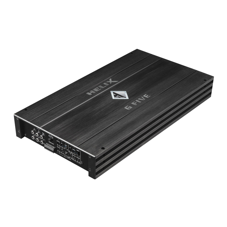
HELIX B Five User manual

BEDIENUNGSANLEITUNG
INSTRUCTION MANUAL
5-Kanal Verstärker
5-Channel Amplifier
B FIVE
deutsch/english
blue

2
Sehr geehrter Kunde,
wir gratulieren Ihnen zum Kauf dieses hochwertigen
HELIX B FIVE Verstärkers.
Er wurde nach neuesten technischen Erkenntnissen ent-
wickelt und zeichnet sich durch hervorragende
Verarbeitung und überzeugende Technologie aus. Sein
ausgezeichnetes Preis-Leistungsverhältnis setzt ebenfalls
neue Maßstäbe und macht ihn zum idealen Allround-
Verstärker in der Highpowerklasse.
Die HELIX B FIVE besteht aus einer 4-Kanal Sektion mit
integrierter, aktiver regelbarer Hochpassweiche für Kanal 1
und 2 und einer Aktivweiche mit Hochpass, Tiefpass und
Bandpass für Kanal 3 und 4. Der Verstärker ist brückbar
und ermöglicht dadurch weitere Anschlussoptionen.
Kanal 5 ist ein analoger Mono Basskanal mit integrierter,
aktiver regelbarer Frequenzweiche für Tiefpass und inte-
griertem Bass Boost.
Viel Spaß mit diesem Produkt wünscht Ihnen das Team von
AUDIOTEC FISCHER
Allgemeines zum Einbau von HELIX-Verstärkern
Um alle Möglichkeiten optimal ausschöpfen zu können,
lesen Sie bitte sorgfältig die nachfolgenden Installations-
hinweise. Wir garantieren, dass jedes Gerät vor Versand
auf seinen einwandfreien Zustand überprüft wurde.
Vor Beginn der Installation unterbrechen Sie den Minus-
anschluss der Autobatterie. Wir empfehlen Ihnen die
Installation von einem Einbauspezialisten vornehmen zu
lassen, da der Nachweis eines fachgerechten Einbaus und
Anschlusses des Gerätes Voraussetzung für die Garantie-
leistungen sind.
Installieren Sie Ihren Verstärker an einer trockenen Stelle
im Auto und vergewissern Sie sich, dass der Verstärker am
Montageort genügend Kühlung erhält. Montieren Sie das
Gerät nicht in zu kleine, abgeschlossene Gehäuse ohne
Luftzirkulation oder in der Nähe von wärmeabstrahlenden
Teilen oder elektronischen Steuerungen des Fahrzeuges.
Im Sinne der Unfallsicherheit muß der Verstärker profes-
sionell befestigt werden. Dieses geschieht über die 4 bei-
liegenden Schrauben, die in eine Montagefläche einge-
schraubt werden, die genügend Halt bieten muss. Bevor
Sie die Schrauben im Montagefeld befestigen, vergewis-
sern Sie sich, dass keine elektrischen Kabel und
Komponenten, hydraulische Bremsleitungen, der
Benzintank etc. dahinter verborgen sind. Diese könnten
sonst beschädigt werden. Achten Sie darauf, daß solche
Teile sich auch in der doppelten Wandverkleidung verber-
gen können.
Allgemeines zum Anschluss der Verstärker
Der Verstärker darf nur in Kraftfahrzeuge eingebaut wer-
den, die den 12V Minuspol an Masse haben. Bei anderen
Systemen können der Verstärker und die elektrische
Anlage des Kfz beschädigt werden.
Die Plusleitung für die gesamte Anlage sollte in einem
Abstand von max. 30 cm von der Batterie mit einer
Hauptsicherung abgesichert werden. Der Wert der
Sicherung errechnet sich aus der maximalen Strom-
aufnahme der Car-Hifi Anlage. Die Kabelverbindungen
müssen so verlegt sein, daß keine Klemm-, Quetsch-oder
Bruchgefahr besteht. Bei scharfen Kanten (Blechdurch-
führungen) müssen alle Kabel gegen Durchscheuern
gepolstert sein.
Ferner dürfen die Stromversorgungskabel niemals mit
Zuleitungen zu Vorrichtungen des Kfz (Lüftermotoren,
Brandkontrollmodulen, Benzinleitungen etc.) verlegt wer-
den.
Um eine sichere Installation zu gewährleisten, sollte auf
hohe Qualität der verwendeten Anschlussmaterialien
geachtet werden.
DEUTSCH


4
1 Power/Protect LED
Die Power/Protect LED zeigt den Betriebszustand des Ver-
stärkers an. Leuchtet die LED grün, ist der Verstärker ein-
geschaltet und betriebsbereit. Bei rot leuchtender LED be-
steht eine Fehlfunktion des Verstärkers.
Diese Fehlfunktion kann unterschiedliche Ursachen
haben, da die HELIX B FIVE mit verschiedenen elektroni-
schen Schutzschaltungen ausgestattet ist. Sie schalten
den Verstärker bei Überhitzung, Über- und Unterspan-
nung, Kurzschluss am Lautsprecherausgang, Impedanz-
unterschreitung und Fehlanschluss ab.
Prüfen Sie in diesem Fall alle Anschlüsse auf Fehler, wie
z.B. Kurzschlüsse, fehlerhafte Verbindungen oder Falsch-
einstellungen und Übertemperatur. Sollte sich der Verstär-
ker nach der Beseitigung der Fehlerquelle nicht wieder
einschalten lassen, liegt ein Defekt vor und das Gerät muß
mit Fehlerbeschreibung und Kaufbeleg zur Reparatur an
den Händler zurückgegeben werden.
2 Anschluss Massekabel
Das Massekabel sollte am zentralen Massepunkt (dieser
befindet sich dort wo der Minuspol der Batterie zum
Metallchassis des Kfz geerdet ist) oder an einer blanken,
von Lack
resten befreiten Stelle des Kfz-Chassis angeschlos-
sen werden. Der empfohlene Querschnitt beträgt
mindestens 25 mm
2.
3 Anschluss Remoteleitung
Die Remoteleitung wird mit dem automatischen Antennen-
anschluss des Steuergerätes (Radio) verbunden. Dieser ist
nur aktiviert, wenn das Steuergerät EIN-geschaltet ist.
Somit
wird der Verstärker mit dem Steuergerät ein- und aus-
geschaltet.
4 Anschluss Batteriekabel
Das +12V Versorgungskabel ist am Pluspol der Batterie
anzuschließen.
Der empfohlene Querschnitt beträgt
mindestens 25 mm
2.
5 Sicherungen
Die Eingangssicherungen sind parallel geschaltet und schüt-
zen vor einem geräteinternen Fehler, d.h. die Anlage muss mit
einer zusätzlichen Sicherung in Nähe der Batterie (max. 30 cm
entfernt) abgesichert werden.
Der Sicherungswert für die HELIX B FIVE beträgt 3 x 30 Ampere.
6 Lautsprecheranschlussklemmen
Zum Anklemmen der Lautsprecherleitungen.
Siehe Anschlussdiagramme Seite 6.
Verbinden Sie niemals die Lautsprecherleitungen mit der Kfz-
Masse (Fahrzeugkarosserie). Dieses kann Ihren Verstärker
zerstören.
Achten Sie darauf, dass alle Lautsprecher-
systeme phasenrichtig angeschlossen sind, d.h. Plus zu
Plus und Minus zu Minus. Vertauschen von Plus und
Minus hat einen Totalverlust der Basswiedergabe zur
Folge. Der Pluspol ist bei den meisten Lautsprechern
gekennzeichnet.
Die Impedanz pro Kanal sollte 2 Ohm nicht unterschreiten,
da die Schutzelektronik den Verstärker sonst abschaltet.
7 & 22 Signaleingänge
Die HELIX B FIVE besitzt 6 Cinch-Eingänge (RCA-
Anschlüsse) als Signaleingänge, die mit den Vorverstärker-
ausgängen / Line Outputs des Steuergerätes (Headunit,
Prozessor, etc.) verbunden werden können.
Bitte beachten Sie, dass aus den letzten beiden Signal-
eingängen (Kanal 5 „L“ und „R“) ein Summensignal für
den 5. Kanal gebildet wird.
8 Hochpegel-Lautsprechereingänge
Die HELIX B FIVE besitzt zusätzlich vier Hochpegel-
Lautsprechereingänge, die direkt mit den Lautsprecher-
ausgängen der Headunit verbunden werden können.
Es wird empfohlen den Highlevel-Eingang ausschließlich
mit dem beiliegenden Anschlusskabel oder mit den optio-
nal erhältlichen HELIX-Kabelbäumen zu verwenden, um
einen Fehlanschluss sowie eine Beschädigung des
Anschlusses zu vermeiden.
9 Eingangssignalschalter
2-Kanal - 4-Kanal - 5-Kanal Modus
2-Kanal Modus: Bei Radios mit einem Stereoausgang wer-
den alle Kanäle des Verstärkers mit diesem Signal ver-
sorgt, d.h. es muss nur der erste und zweite Cinch bzw.
Highlevel-Eingangskanal belegt werden. In diesem Modus
wird das Eingangssignal von Kanal 1 parallel auf Kanal
3 und das von Kanal 2 parallel auf Kanal 4 weitergeleitet.
Für den 5. Kanal (Subwooferausgang) wird aus dem
Eingangssignal von Kanal 1 und 2 ein Summensignal
gebildet. Bitte beachten Sie, dass sich die Fader- und
Balanceregler des Steuergerätes somit gleichermaßen auf
Kanal 3 bzw. 4 auswirken, wie auf Kanal 1 und 2.

5
4-Kanal Modus: Bei Radios mit 2 Stereoausgängen wird
jeder der 4 Lautsprecherausgänge mit dem dazugehöri-
gem Eingangssignal versorgt. Der 5. Kanal (Subwoofer-
ausgang) wird mit einem Summensignal der 4 Eingangs-
signale versorgt.
5-Kanal Modus: Hierbei müssen alle Cinch-Eingänge bzw.
Highlevel-Eingänge belegt werden, also alle 5 Kanäle. Da
der 5. Kanal einen Stereoeingang besitzt, sollten beide
Eingänge belegt werden. Für den Fall, dass nur ein
Eingang belegt wird, muss die Eingangsempfindlichkeit
angepasst werden.
Im 5-Kanal Modus muss bei Verwendung der Highlevel-
Eingänge zusätzlich der 5. Cincheingang belegt werden.
10, 14 & 21 Levelregler für Eingangsempfindlichkeit
Kanäle 1 bis 5
Mit Hilfe dieser Regler kann die Eingangsempfindlichkeit
der Kanäle an die Ausgangsspannung des angeschlosse-
nen Steuergeräts angepasst werden. Diese Regler sind
keine Lautstärkeregler, sondern dienen nur der
Anpassung. Der Regelbereich beträgt 0,2 bis 6 Volt.
Mit dem Regler 10 können die Kanäle 1 und 2 eingestellt
werden, mit dem Regler 14 die Kanäle 3 und 4 und
Kanal 5 mit dem Regler 21.
11, 15 & 20 Regler für Bassanhebung Kanäle 1 bis 5
Mit Hilfe dieser Regler kann das Basssignal bei 45 Hz von
0 bis 18 dB angehoben werden.
12 Umschalter für Fullrange - Hochpass Kanal 1 und 2
Zur Umschaltung der internen, aktiven Frequenzweiche
auf Hochpass oder Fullrange.
Wird der Schalter auf HPF (Hochpassfilter) gestellt, so kann
mit Hilfe des Reglers 13 die exakte Übernahmefrequenz
für den Hochpass eingestellt werden.
Bei der Schalterstellung FULL (Fullrange) ist die interne
Frequenzweiche nicht aktiv.
Für den Kanal 1 und 2 ist es nicht möglich einen Tiefpass-
filter einzustellen, da diese Kanäle speziell für den Betrieb
von Hochtönern optimiert wurden, sofern der Schalter auf
HPF gestellt wird.
13 Frequenzeinstellregler für Hochpass
Kanal 1 und 2
Zur Einstellung der Trennfrequenz von 15 Hz bis 4000 Hz.
Dieser Regler wird erst aktiviert, wenn Schalter 12 auf
HPF (Hochpassfilter) eingestellt ist.
16 Umschalter für Hochpass - Fullrange - Tiefpass /
Bandpass Kanal 3 und 4
Zur Umschaltung der internen, aktiven Frequenzweiche
auf Hochpass, Fullrange oder Tiefpass bzw. Bandpass.
Wird dieser Schalter auf HPF (Hochpass) gestellt, so kann
mit Hilfe des Reglers 11 die exakte Übernahmefrequenz
für den Hochpass eingestellt werden.
Bei Schalterstellung FULL (Fullrange) ist die interne
Frequenzweiche nicht aktiv.
Bei Schalterstellung LPF (Tiefpassfilter) ist der Hochpass
immer aktiv. Das heißt, es wird in jedem Fall ein Bandpass
gebildet. Mit dem Regler 17 wird der Hochpass und mit dem
Regler 18 der Tiefpass eingestellt. So kann jeder beliebige
Bandpass zwischen 15 Hz und 4000 Hz eingestellt werden.
Achtung! Bitte vergewissern Sie sich, dass beim Einstellen
eines Bandpasses die Übernahmefrequenzen von Hoch- und
Tiefpass 2 Oktaven auseinander liegen, um einen Pegel-
verlust zu vermeiden! Die eingestellte Frequenz des
Tiefpasses muss immer höher sein als die des Hochpasses!
Das heißt: Wird das Tiefpasssignal z. B. auf 320 Hz eingestellt,
so sollte der Hochpass um 2 Oktaven tiefer auf ca. 80 Hz
eingestellt werden (1 Oktave = Frequenzverdopplung oder
Frequenzhalbierung).
17 Frequenzeinstellregler für Hochpass
Kanal 3 und 4
Zur Einstellung der Trennfrequenz von 15 Hz bis 4000 Hz.
Dieser Regler wird erst aktiviert, wenn Schalter 12 auf HPF
(Hochpassfilter) eingestellt ist.
Hz5K2K
15 Hz 4 kHz
variabel
Hz5K2K
15 Hz 4 kHz
variabel

6
ANSCHLUSS DER LAUTSPRECHER HELIX B FIVE
Kanal 2 (CH3 + CH4 gebrückt)
Kanal 1 (CH1 + CH2 gebrückt)
Kanal 3 Subwoofer
Kanal 1 Kanal 2
Kanal 3 Kanal 4
Kanal 5 Subwoofer
Kanal 1 Kanal 2
Kanal 3 Kanal 4
Kanal 5 Subwoofer
5-Kanal Betrieb 3-Kanal Betrieb
Vollaktiv-Betrieb
19 Frequenzeinstellregler für Tiefpass
Kanal 5
Zur Einstellung der Trennfrequenz von 40 Hz bis 4000 Hz.
Dieser Regler ist immer aktiv.
Hz5K2K
40 Hz 4 kHz
variabel
18 Frequenzeinstellregler für Tiefpass / Bandpass
Kanal 3 und 4
Zur Einstellung der Trennfrequenz von 40 Hz bis 4000 Hz.
Dieser Regler wird erst aktiviert, wenn Schalter 12 auf LPF
(Lowpassfilter) eingestellt ist.
Hz5K2K
40 Hz 4 kHz
variabel

7
VOLLAKTIV-BETRIEB
Die HELIX B FIVE bietet umfangreiche Möglichkeiten, ein
Lautsprechersystem vollaktiv zu betreiben. Das bedeutet,
dass jeder Lautsprecher an einen separaten Kanal ange-
schlossen wird und keine passiven Frequenzweichen ein-
gesetzt werden. Für diesen Betriebsmodus werden klassi-
scherweise ein 2-Wege-Lautsprechersystem, bestehend
aus jeweils zwei Hochtönern und zwei Tieftönern, und ein
Subwoofer verwendet. Hierfür eignen sich hervorragend
die ideal darauf abgestimmten HELIX blue Lautsprecher-
systeme, wie beispielsweise das „HELIX B 62C“ (2-Wege-
Komponentensystem) und der „HELIX B 12E“ (30 cm Sub-
woofer im geschlossenen Gehäuse).
Lautsprecheranschluss:
Jeder Lautsprecher wird ohne den Einsatz von passiven
Frequenzweichen direkt an einen separaten Kanal der
Endstufe angeschlossen. Dabei sollten die Lautsprecher
wie folgt angeschlossen werden:
- Die Hochtöner (des „B 62C“) werden im Vollaktiv-
Betrieb direkt an die Lautsprecherausgänge 1 („CH 1“)
und 2 („CH 2“) des Verstärkers angeschlossen.
- Die Tieftöner des („B 62C“) werden an die Lautspre-
cherausgänge 3 („CH 3“) und 4 („CH 4) angeschlossen.
- Der Subwoofer („B 12E“) wird an den 5. Lautsprecher-
ausgang („CH 5“) angeschlossen.
Signaleingänge:
Für die Belegung der Signaleingänge stehen im Vollaktiv-
Betrieb verschiedene Anschlussmöglichkeiten zur Verfü-
gung. Eine detaillierte Erklärung der Funktionsweise des
Eingangssignalschalters (9) finden Sie auf Seite 4. Mit Hil-
fe der GAIN-Regler kann die Lautstärke der einzelnen
Lautsprecherausgänge aufeinander abgestimmt werden.
- 2-Kanal-Modus: Hierbei werden nur die Cinch- bzw.
Hochpegel-Signaleingänge von Kanal 1 („CH 1“) und
2 („CH 2“) belegt. Der Eingangssignalschalter wird auf
„2-CH“ eingestellt.
- 4-Kanal-Modus: Hierbei werden die Cinch- bzw. Hoch-
pegel-Signaleingänge von Kanal 1 bis 4 belegt. Bei
dieser Variante wird jedem Lautsprecherausgang das
dazugehörige Eingangssignal zugeordnet, der Sub-
wooferausgang erhält ein Summensignal aus allen Ein-
gangssignalen. Der Eingangssignalschalter wird auf
„4-CH“ gestellt.
- 5-Kanal-Modus: Hierbei werden alle fünf Cinch-
Eingänge des Verstärkers belegt und jeweils dem
dazugehörigen Lautsprecherausgang zugeordnet. Bei
Verwendung des Hochpegel-Signaleingangs wird der
4-Kanal-Modus empfohlen. Der Eingangssignalschalter
wird auf „5-CH“ gestellt.
Frequenzweiche:
Die richtige Einstellung der internen Frequenzweiche ist in
diesem Betriebsmodus besonders wichtig, da es anson-
sten zu Beschädigungen der angeschlossenen Lautspre-
cher kommen kann.
- Kanal 1 und 2: Bei diesen Kanälen muss in der internen
Frequenzweiche ein Hochpassfilter („HPF“) eingestellt
werden (Schalter 12). Üblicherweise liegt diese Trenn-
frequenz zwischen 2 kHz und 4 kHz. Für das Beispiel-
system B 62C sollte ein Wert von ca. 3 kHz gewählt
werden.
- Kanal 3 und 4: Bei diesen Kanälen muss in der internen
Frequenzweiche ein Bandpass aktiviert werden. Dazu
wird der Tiefpassfilter („LPF“) eingestellt (Schalter 16),
wodurch automatischein Bandpass gebildet wird. Die
Frequenz des Tiefpassfilters (18) sollte auf die gleiche
Frequenz wie die Hochpassfrequenz von Kanal 1
und 2, also ca. 3 kHz, eingestellt werden. Anschließend
wird zusätzlich noch eine Hochpassfrequenz (17)
eingestellt, um einen Bandpass zu konfigurieren. Der
Wert sollte bei unserem System zwischen 70 Hz und
90 Hz liegen. Der Bass Boost wird im Vollaktiv-Modus
nicht verwendet.
- Kanal 5: Bei diesem Subwoofer-Kanal ist der Tiefpass
immer aktiv. Der Tiefpassfilter (19) sollte auf die
gleiche Frequenz eingestellt werden, wie der Hoch-
passfilter des 3. und 4. Kanals, also zwischen 70 Hz
und 90 Hz. Zusätzlich kann für diesen Kanal die Inten-
sität der Tieftonwiedergabe über den Bass-Boost-
Regler (20) verstärkt werden.


9
Dear Customer,
congratulations on your purchase of this high power HELIX
B FIVE amplifier.
Developed and designed with state-of-the-art technology
it highlights excellent manufacturing and best quality and
sets new standards with an excellent price/performance
ratio.
The HELIX B FIVE features a 4-channel section with an
integrated, variable active highpass frequency crossover
for channel 1 and 2 and an active crossover with highpass,
lowpass and bandpass for channel 3 and 4. The amplifier
can be bridged for more connecting options.
Channel 5 is a digital mono bass channel with an integra-
ted, variable active crossover for lowpass and bass boost.
We wish you many hours of enjoyment with your new
HELIX amplifier.
Yours
AUDIOTEC FISCHER Team
General installation instructions for HELIX amplifiers
To find out how HELIX amplifiers work best for you, read
this manual carefully and follow the instructions for instal-
lation. We guarantee that this product has been checked
for proper functioning before shipping.
Before you start installation, disconnect the car battery at
the minus pole. We would urge you to have the installation
work carried out by a specialist as verification of correct
installation and connection of the unit is a prerequisite for
warranty cover of the HELIX amplifier.
Install your amplifier at a dry location where there is suffi-
cient air circulation to ensure adequate cooling of the
equipment. For safety reasons, the amplifier must be secu-
red in a professional manner. This is performed by means
of four fixing screws screwed into a mounting surface
offering sufficient retention and stability.
Before drilling the holes for the screws, carefully examine
the area around the installation position and make sure
that there are no electrical cables or components, hydrau-
lic brake lines or any part of the petrol tank located behind
the mounting surface - otherwise these could be dama-
ged. You should be aware of the fact that such components
may also be concealed in the double-skin trim
panels/mouldings.
General instruction for connecting the amplifiers
The HELIX amplifiers may only be installed in motor vehi-
cles which have a 12 Volt minus pole connected to the
chassis ground. Any other system could cause damage to
the amplifier and the electrical system of the vehicle.
The plus cable from the battery for the complete system
should be provided with a main fuse at a distance of max.
30 cm from the battery. The value of the fuse is calculated
from the maximum total current input of the car audio
system.
Install the cabling in a manner which precludes any danger of
the leads being exposed to shear, crushing or rupture forces.
If there are sharp edges in the vicinity (e.g. holes in the body-
work) all cables must be cushioned and protected to prevent
fraying.
Never lay the power supply cables adjacent to leads and
lines connecting other vehicle equipment (fan motors, fire
detection modules, gas lines etc.).
In order to ensure safe installation, use only high-quality con-
nections and materials. Ask your dealer for high quality acces-
sories.
ENGLISH


11
1 Power/Protect LED
The Power/Protect LED indicates the operating state
of the amplifier. A green LED shows that the amplifier is
ready for operation.
A red LED indicates that a malfunction has occurred.
A malfunction may have different causes as the HELIX B
FIVE is equipped with different protective circuits. These
protections shut off the amplifier in case of overheating,
over- and undervoltage, short-circuit on loudspeakers,
low impedance and false connection.
Please check for connecting failures such as short-
circuits, wrong connections, wrong adjustments and over-
temperature. If the amplifier does not turn on it is defect
and has to be send to your local authorized dealer for
repair service. A detailed description of the malfunction
and the purchase receipt has to be attached.
2 Connecting the ground cable
The ground cable should be connected to a central
ground reference point (this is located where the negative
terminal of the battery is grounded at the metal body of the
vehicle), or to a bright bare-metal location on the vehicle
chassis, i.e. an area which has been cleaned of all paint
residues. Recommended cross section: min. 25 mm2.
3 Connecting the remote lead
The remote lead should be connected to the automatic
antenna (aerial positive) output of the head unit (radio).
This is only activated if the head unit is switched ON. Thus
the amplifier is switched on and off with the head unit.
4 Connecting the battery cable
Connect the +12 V power cable to the positive terminal of
the battery. Recommended cross section: min. 25 mm2.
5 Fuses
The input fuses are connected in parallel and provide
protection against an internal equipment fault, i.e. the
system must be additionally protected by a further line
fuse located in the vicinity of the battery (max. distance
from battery: 30 cm / 12"). The fuse value for the HELIX
B FIVE is 3 x 30 Amperes.
6 Speaker terminals
To connect the speaker cables. See figures on page 13.
Never connect the loudspeaker cables with the car
chassis ground. It damages your amplifier. Ensure that the
loudspeaker systems are correctly connected (phase), i.e.
plus to plus and minus to minus. Exchanging plus and
minus causes a total loss of bass reproduction. The plus
pole is indicated on most speakers.
The impedance per channel should not be lower than
2 Ohms. In this case the protection electronics shut down
the amplifier.
7 & 22 Signal inputs
The HELIX B FIVE is equipped with 6 RCA inputs. They can
be connected with the pre-amplifier outputs / line outputs
of the control device (head unit, processor etc.).
Please consider that a sum signal for the 5th channel is
formed by the last two signal inputs (channel 5 „L“
and „R“).
8 Highlevel speaker input
The HELIX B FIVE is equipped with four extra highlevel
speaker inputs. They can be directly connected to the
speaker outputs of the head unit.
We recommend to operate the highlevel input only
with the enclosed connecting cable or with a HELIX wire
harness (optional) to avoid wrong connections or damage
of the connector.
9 Input signal mode switch
2-channel - 4-channel - 5-channel mode
2-channel mode: When head units with one stereo
output are operated, all amplifier channels are supplied
with this signal. This means, that only the first and
second RCA / highlevel input must be connected.
In this mode the channel 1 input signal is relayed
parallel to channel 3 and channel 2 is relayed parallel to
channel 4. For channel 5 (subwoofer output) a sum
signal is formed by the channel 1 and channel 2 input
signals.

12
Please consider that the fader- and balance control of the
head unit have the same effect on channels 3 and 4 as on
channels 1 and 2.
4-channel mode: When operating headunits with two
stereo outputs, all four speaker outputs are supplied with
the corresponding input signal. Channel 5 (subwoofer
output) is supplied by a sum signal of the 4 input signals.
5-channel mode: In this mode all RCA inputs must be
connected (all five channels). As channel 5 has a stereo
input, both should be used. In case only one input is con-
nected, the sensitivity must be adjusted.
When using the highlevel inputs in the 5 channel mode, the
5th RCA channel must be connected.
10, 14 & 21 Level control for input sensitivity
channels 1 to 5
These controls can be used to match the input sensitivity
of the individual channels to the output voltage of the
connected head unit. These controls are not volume
controls and are solely intended for the purpose of
sensitivity trimming. The control range extends from
0,2 to 6 volts.
Control 10: To adjust channel 1 and 2.
Control 14: To adjust channel 3 and 4.
Control 21: To channel 5.
11, 15 & 20 Bass-Boost evel control channels 1 to 5
To raise the bass signal from 0 to 18 dB at 45 Hz.
12 Switch for fullrange - highpass channel 1 and 2
To set the integrated, active crossover on highpass or
fullrange.
When the switch is set on HPF (highpass), the exact
crossover frequency for highpass can be adjusted with
control 13.
In position FULL (fullrange) the internal frequency
crossover is not active.
It is not possible to adjust a lowpass filter for channels
1 and 2, as these channels were optimized to operate
tweeters as long as the switch is in position HPF.
13 Frequency control for highpass channel 1 and 2
To adjust the crossover frequency from 15 Hz to 4000 Hz.
This control is not active before switch 12 is set on HPF
(highpass filter).
16
Switch for highpass - fullrange - lowpass / bandpass
channel 3 and 4
To set the integrated active crossover on highpass,
fullrange or lowpass / bandpass.
When the switch is set on HPF (highpass), the exact
crossover frequency for highpass can be adjusted with
control 11.
In position FULL (fullrange) the internal frequency cross-
over is not active.
In position LPF (lowpass) highpass is always active. This
means that a bandpass is formed in any case. When using
control 17 for highpass and control 18 for lowpass any
bandpass between 15 Hz and 4000 Hz can be adjusted.
Caution! To avoid a loss of sound pressure, make sure that
the crossover frequencies are seperated by 2 octaves
when adjusting the bandpass. The adjusted lowpass
frequency must always be higher than the highpass
frequency!
This means for example: If the lowpass signal is set on
320 Hz, the highpass should be lowered by 2 octaves to
80 Hz. (1 octave = double frequency or half frequency).
17 Frequency control for highpass channel 3 and 4
To adjust the crossover frequency from 15 Hz to 4000 Hz.
This control is not active before switch 12 is set on HPF
(highpass filter).
Hz5K2K
15 Hz 4 kHz
variabel
Hz5K2K
15 Hz 4 kHz
variabel

13
SPEAKER CONNECTIONS HELIX B FIVE
Channel 2 (CH3 + CH4 bridged)
Channel 1 (CH1 + CH2 bridged)
Channel 3 subwoofer
Channel 1 Channel 2
Channel 3 Channel 4
Channel 5 subwoofer
Channel 1 Channel 2
Channel 5 subwoofer
5-channel 3-channel
Fully active
Channel 3 Channel 4
Hz5K2K
40 Hz 4 kHz
variabel
Hz5K2K
40 Hz 4 kHz
variabel
18 Frequency control for lowpass / bandpass
channel 3 and 4
To adjust the crossover frequency from 40 Hz to 4000 Hz.
This control is not active before switch 12 is set on LPF
(lowpass filter).
19 Bass-Boost level control
channel 5
To adjust the crossover frequency from 40 Hz to 4000 Hz.
This control is always active.

14
FULLY ACTIVE MODE
The HELIX B FIVE offers many different options for
operating a speaker system in fully active mode. This
means that each speaker is connected to a separate
channel and no passive crossovers are used. A 2-way
speaker system, consisting of two tweeters and two
woofers each, and one subwoofer is the typical choice for
this operating mode. The ideally coordinated HELIX blue
speaker systems, such as the „HELIX B 62C“
(2-way component system) and the „HELIX B 12E“
30-cm subwoofer in a closed box), are perfectly suited to
this use.
Connecting the speakers:
Each speaker is connected directly to a separate channel
on the power amplifier without the use of any passive
crossovers. The speakers should be connected as follows:
- In fully active mode, the tweeters (of the „B 62C“) are
directly connected to speaker outputs 1 („CH 1“) and
2 („CH 2“) on the amplifier.
- The woofers (of the „B 62C“) are connected to speaker
outputs 3 („CH 3“) and 4 („CH 4“).
- The subwoofer („B 12E“) is connected to the 5th
speaker output („CH 5“).
Signal inputs:
There are a number of different connection options for the
allocation of the signal inputs in fully active mode. You will
find a detailed explanation of the way in which the input
signal switch (9) works on Page 4. The GAIN control knob
is used to adjust the volume of the individual speaker
outputs.
- 2-channel mode: In this case, only the cinch or high-
level signal inputs from Channel 1 („CH 1“) and
2 („CH 2”) are supplied with the signal. The input
signal switch is set to „2-CH“.
- 4-channel mode: In this case, the cinch or high-level
signal inputs from channels 1 to 4 are supplied with
the signal. For this option, the corresponding input
signal is allocated to each speaker output; the subwoofer
output is supplied with the sum of all the input signals.
The input signal switch is set to „4-CH“.
- 5-channel mode: In this case, all five cinch inputs on
the amplifier are supplied with the signal and the
signal is then allocated to the corresponding speaker.
When using the high-level signal input, we recommend
using the 4-channel mode. The input signal switch
is set to „5-CH“.
Crossover:
It is particularly important to set the internal crossover
correctly. If not, the speakers connected might be damaged
as a result.
- Channel 1 and 2: For these channels, a highpass filter
(„HPF“) must be set in the internal crossover (switch
12). The cut-off frequency is usually between 2 kHz
and 4 kHz. For our example system, the B 62C, this
value should be set at approx. 3 kHz.
- Channel 3 and 4: For these channels, a bandpass must
be activated in the internal crossover. To do so, set the
lowpass filter („LPF“) (switch 16), which automatically
forms a bandpass. The frequency of the lowpass filter
(18) should be set to the same frequency as the
highpass frequency for Channel 1 and 2, i.e. approx.
3 kHz. After that, another highpass frequency (17) is
set to configure a bandpass. For our system, the value
should lie somewhere between 70 Hz and 90 Hz. Bass
Boost is not used in the fully active mode.
- Channel 5: The low pass is always active for this
subwoofer channel. The lowpass filter (19) should be
set to the same frequency as the highpass filter for
Channels 3 and 4, i.e. between 70 Hz and 90 Hz. In
addition, the intensity of the woofer reproduction can
be increased for this channel by adjusting the
Bass-Boost control knob (20).


Audiotec Fischer GmbH
Gewerbegebiet Lake II · Hünegräben 26 · D-57392 Schmallenberg
Tel.: +49 (0) 29 72-97 88 0 · Fax: +49 (0) 29 72-97 88 88
E-mail: helix@audiotec-fischer.com · Internet: www.audiotec-fischer.com
Other manuals for B Five
1
Table of contents
Languages:
Other HELIX Amplifier manuals
HELIX
HELIX B Four User manual
HELIX
HELIX PP20 DSP User manual
HELIX
HELIX M ONE X User manual
HELIX
HELIX P SIX DSP MK2 User manual
HELIX
HELIX H 500 ESPRIT User manual

HELIX
HELIX P SIX DSP MK2 User manual
HELIX
HELIX DARK BLUE FOUR User manual
HELIX
HELIX C ONE User manual
HELIX
HELIX M SIX User manual
HELIX
HELIX Competition SPXL 1000 User manual
HELIX
HELIX V TWELVE DSP User manual
HELIX
HELIX HXA 40 User manual

HELIX
HELIX C ONE User manual
HELIX
HELIX ULTIMATE P SIX DSP User manual
HELIX
HELIX P 200 User manual
HELIX
HELIX B Five User manual
HELIX
HELIX G ONE User manual
HELIX
HELIX P ONE MK2 User manual
HELIX
HELIX H 400 ESPRIT User manual
HELIX
HELIX V EIGHT DSP MK2 User manual
