Precision Sound Lab RCA socket Mk7 User manual

RCA sockets Mk7 kit - Fitting instructions
Rev. 07/19
WARNING! RISK OF ELECTRIC SHOCK
UNPLUG MAINS CABLE BEFORE STARTING
RCA SOCKET INSTALLATION
Thank you for choosing our RCA sockets kit, it is Designed and Made in Italy by Precision Sound Lab
using the best technologies and materials for superior performance and durability.
Technics is a brand of Panasonic Corporation, all rights reserved to the owner, use is only for reference.
Our kit is designed to fit all the Technics SL-1200/1210 from Mk2 to Mk6 models.
This kit is not suitable for SL-1200 GAE/G/Gr and Mk7 models.
Worldwide Registered Design by Precision Sound Lab
Page 1
Page 2
-1x aluminum RCA sockets box, with cover and 3x flat head M4 screws
-1x stainless steel adaptor flange
-2x button head M4 screws
-1x 13cm interconnect phono cable
-1x 120cm ground cable
-1x black plastic cap
-1x 3cm silver coated jumper
-1x 2.5mm allen key
-1x 30cm 4% silver soldering wire
-1x 30cm desoldering braid
Each kit contains:
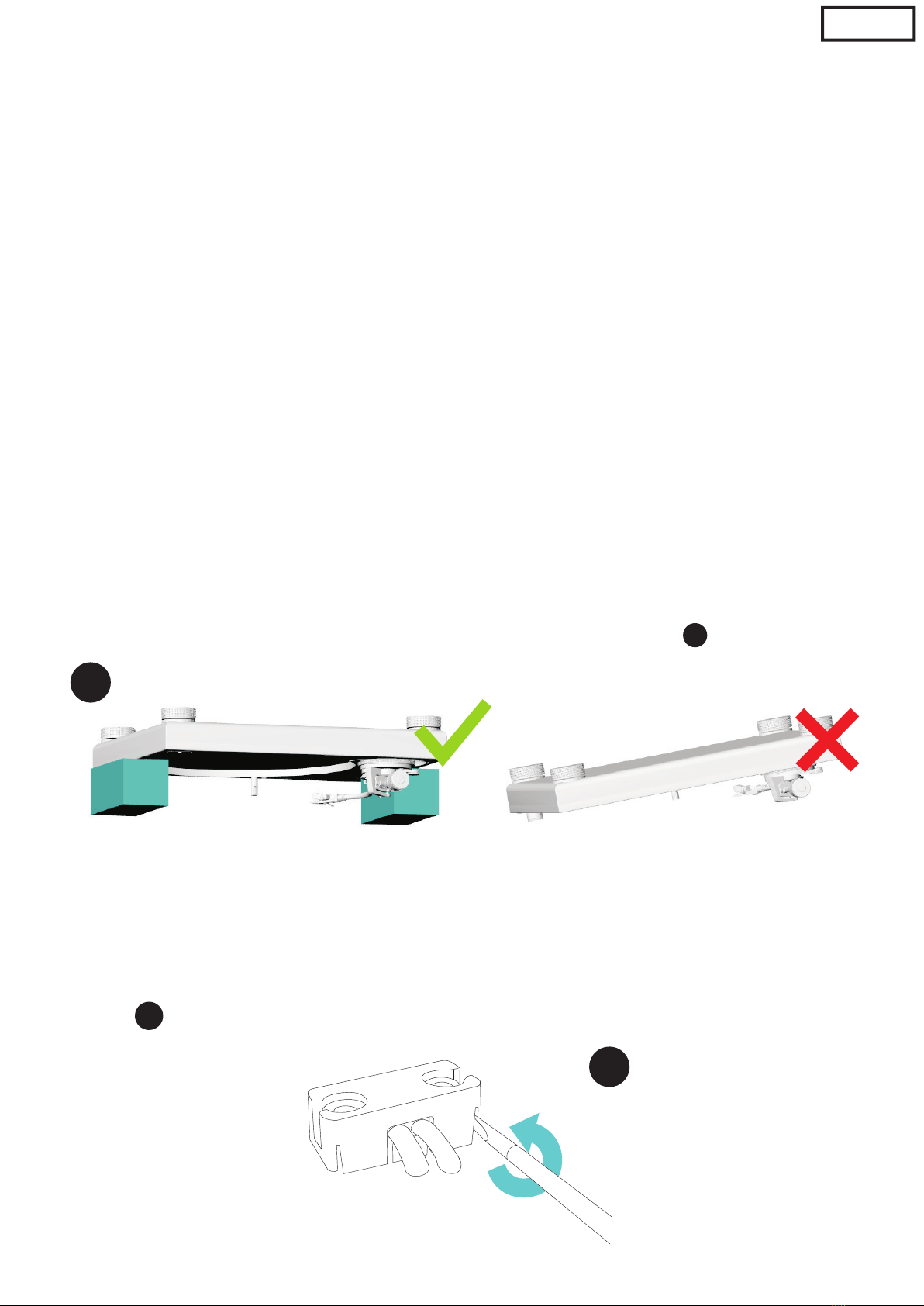
Step 1 - Preparing your working area
Disconnect the turntable from mains, lock the tonearm on its rest, remove tonearm
counterweight then remove the platter using the 2 holes on it.
Please be careful with platter magnet on the lower side, we suggest to put the platter
on a soft surface with the magnet facing upwards to avoid damages.
If you have original dustcover use it as a jig, placing it upside downon a soft cloth to
prevent scratches, if the dustcover is missing use two objects with the same height to
place the turntable upside down, the object (you can use 2 or more books e.g.) must touch
just the cabinet, do not put tonearm in contact with it - see figure
11 1
Unscrew the 4 turnable feet, remove all the rubber base screws then remove rubber base.
Locate the cable holder on the bottom of tonearm base, unscrew the two Phillips screws
then using a small flat screwdriver open the original cable clamp and remove it -
see figure
Step 2 - Turntable base disassembling and cable removing /reinstalling
2
2
1
Page 3
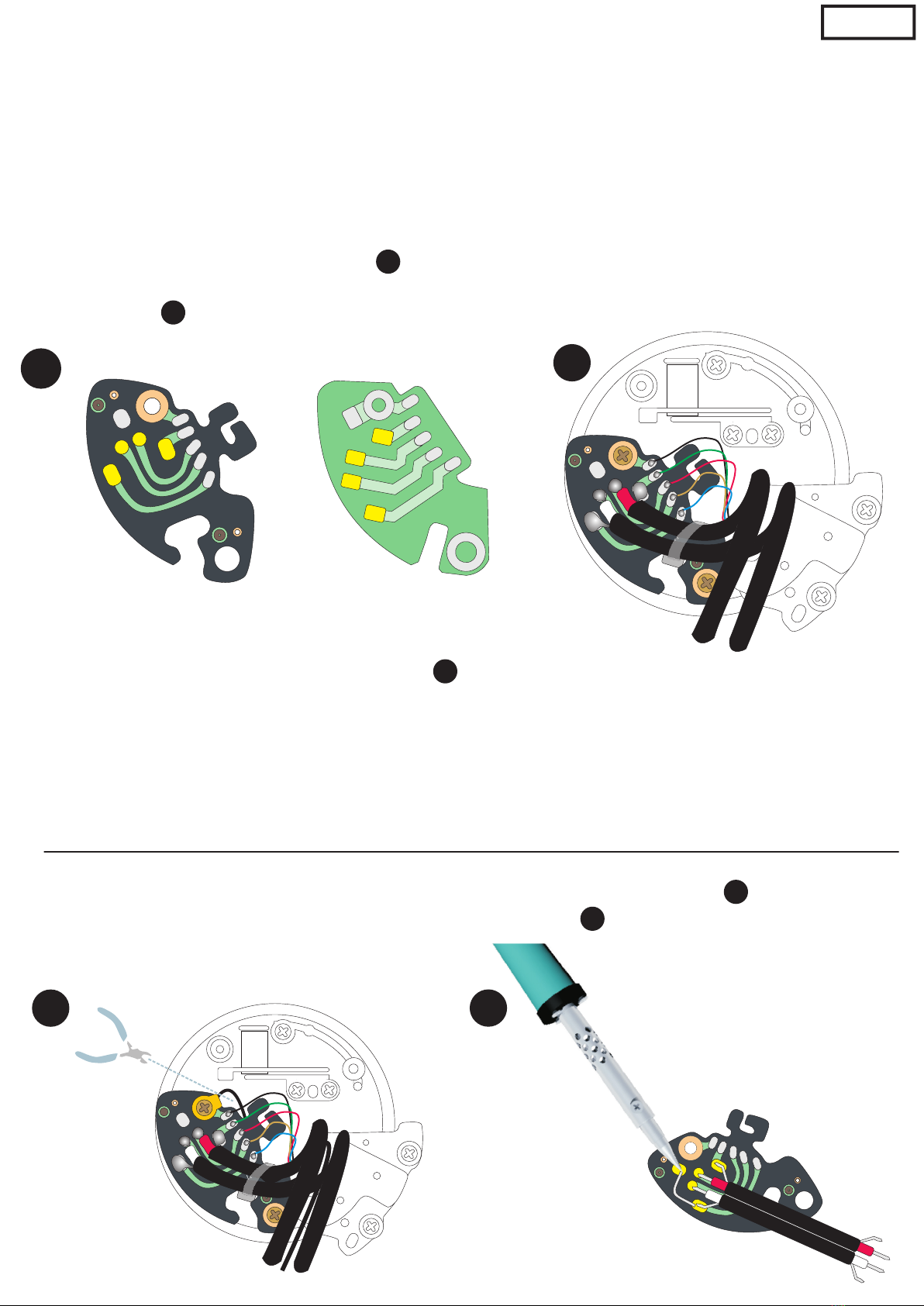
Remove the original metal flange at the bottom of tonearm base and keep the two small
Phillips screws that will be used to mount the modified flange.
Once removed the original flange you have access to the interconnect PCB for the tonearm
wires.ELR+RL+__3
E
L
R
+R
L+
_
_
Cut the original cable tie and desolder the original phono cables, use the supplied
desoldering braid to clean the welding pads (marked in yellow), basically you can find two
style of interconnect PCB, use figure for reference.
Solder the new cable with the supplied soldering wire and install the supplied plastic cable
tie as in figure .
3
3
E
L
R
R+
L+
_
_
R
L
R
L
E
+
+
__
0S F D P I1 82- 1
9UO 4H B
E
L
R
R+
L+
_
_
4
Ground removing mod: if you want to remove original grounding cable follow these
instructions, the ground will be routed through one of the channel screen wire.
5
Cut the external grounding cable from the solder tag as shown in figure then bend and
solder the supplied silver wire jumper as shown in figure
4
If you prefer to keep external ground just leave 5cm of original cable soldered to the tag.
5
6
HB
E
L
R
R+
L+
_
_
6
NOTE: put cable tie knot on the side as in figure to allow the complete movement of tonearm base
height regulation (VTA).
Letting the knot facing upwards could not allow regulation of VTA to reach the lowest position.
4
Page 4
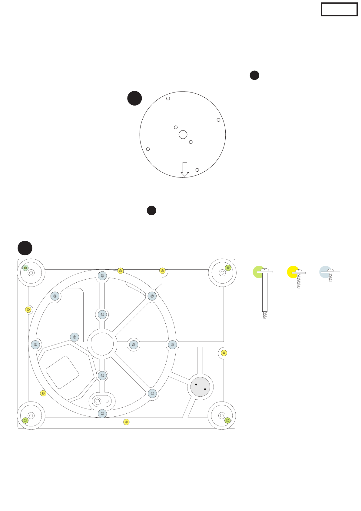
Step 3 - Turntable base reassembling
Install the new flange passing the phono wires through the flange central hole then assemble it using the
2 original small screws.
You have to install the flange with the shiny brushed side facing upwards, the correct position angle is
marked by an arrow that have to point to the dustcover hinge, as in figure .
7
7
3
Reassemble the rubber base, use fig. as reference for screws positions
8
8
TIP : Reassembling the screws do half a turn anticlockwise before screwing it back, in this way you
can insert the screw to the original threading.
Disassemble RCA box cover using the supplied allen key, fit the box in the rubber base hole letting the
wires passing through the central hole.

Page 5
Assemble RCA box using the two button head M4 screw and the allen key to the corresponding threaded
holes on the flange.
To facilitate the assembling we suggest to insert the first screw only half the way down, then insert the
second screw and tighten both.
Proceed to solder the wires to the RCA sockets using the supplied soldering wire.
To help the soldering of the wires screen there is a presoldered pad on both RCA body.
PLEASE note: if you use a separated prephono (especially tube drived) in most case you need to have
separate ground, please let me know where the deck is connected.
Tonearm signal layout is very simple, it has 2 channel one per side, the cable have HOT (central) and
SCREEN (external screening).
Relatively to the connection on the RCA sockets we have:
RED HOT to central pin of RIGHT RCA
RED SCREEN to body of RIGHT RCA
WHITE HOT to central pin of LEFT RCA
WHITE SCREEN to body of RIGHT RCA
Please note: in some case (on the decks until circa 1997) the tonearm wires are held in place with a strip
of fabric tape, as the wires are very very thin it can happens that removing this tape you can accidentally
detach one or more of the wires. Double check these thin wires, in case re-strip it and solder in place.
If you choose to use the external grounding cable strip the original black cable and solder it to the corres-
ponding soldering tag located on the ground post.
If you choose to have the ground removing mod you can disassemble the ground post and plug the hole
with the supplied black plastic cap.
Reassemble the box cover using the flat head M4 screws, reassemble the four feet and the turntable
platter, connect the turntable to your audio gear and enjoy your music!
This manual suits for next models
1
Table of contents


