PREFORMED LINE PRODUCTS COYOTE 80805258 User manual

1
COYOTE® CLOSURE
FOR UNDERGROUND, AERIAL, AND BURIED SPLICES
6.0" x 22" • 8.5" x 22"
(15.24 cm x 55.88 cm • 21.59 cm x 55.88 cm)
OCTOBER 2004
Be sure to read and completely understand this procedure before applying product. Be sure to select
the proper PREFORMED™ product before application.
PLEASE NOTE: For OPGW application, see procedure entitled, “OPGW Cable and End Plate Prepara-
tion for COYOTE® Closure” (SP2849).
CONTENTS PAGE
1. NOMENCLATURE ................................2,3,4
2. DESCRIPTION AND CLOSURE
CAPACITIES ...............................................5
3. END PLATE CONFIGURATIONS ...............5
4. CABLE PREPARATION–LOCK-TAPE
SEALANT APPLICATION ........................6,7
5. INTERNAL BOND PROCEDURE ...............7
6. END PLATE PREPARATION ......................8
7. END PLATE ASSEMBLY .........................8,9
8. UNITUBE PREPARATION ........................10
9. INSTALLING TRANSITION
COMPARTMENT FOR SINGLE
TUBE CABLE ......................................10,11
10. SECURING UNITUBE CABLE
IN THE TRANSITION
COMPARTMENT ..................................11,12
11. ROUTING AND STORING FIBER
IN THE STORAGE
COMPARTMENT .......................................12
CONTENTS PAGE
12. INSTALLING FIBERS INTO
TRANSPORT TUBES AND SECURING
TO STORAGE COMPARTMENT ........12,13
13. SECURING TRANSPORT TUBES
AND ROUTING FIBERS IN
SPLICE TRAYS ................................... 14-17
14. ROUTING LOOSE BUFFER TUBE
CABLE .................................................17,18
15. INSTALLING COYOTE CLOSURE
SHELLS ................................................... 19
16. EXTERNAL BOND PROCEDURE ............20
17. STRAND MOUNT PROCEDURE .............21
18. MANHOLE SUPPORT BRACKET
KIT INSTALLATION .............................21,22
19. BURIED INSTALLATION ..........................22
20. MAINTENANCE PROCEDURES ..............22
21. SAFETY CONSIDERATIONS ...................22
2
©2004 Preformed Line Products Company. All rights reserved.
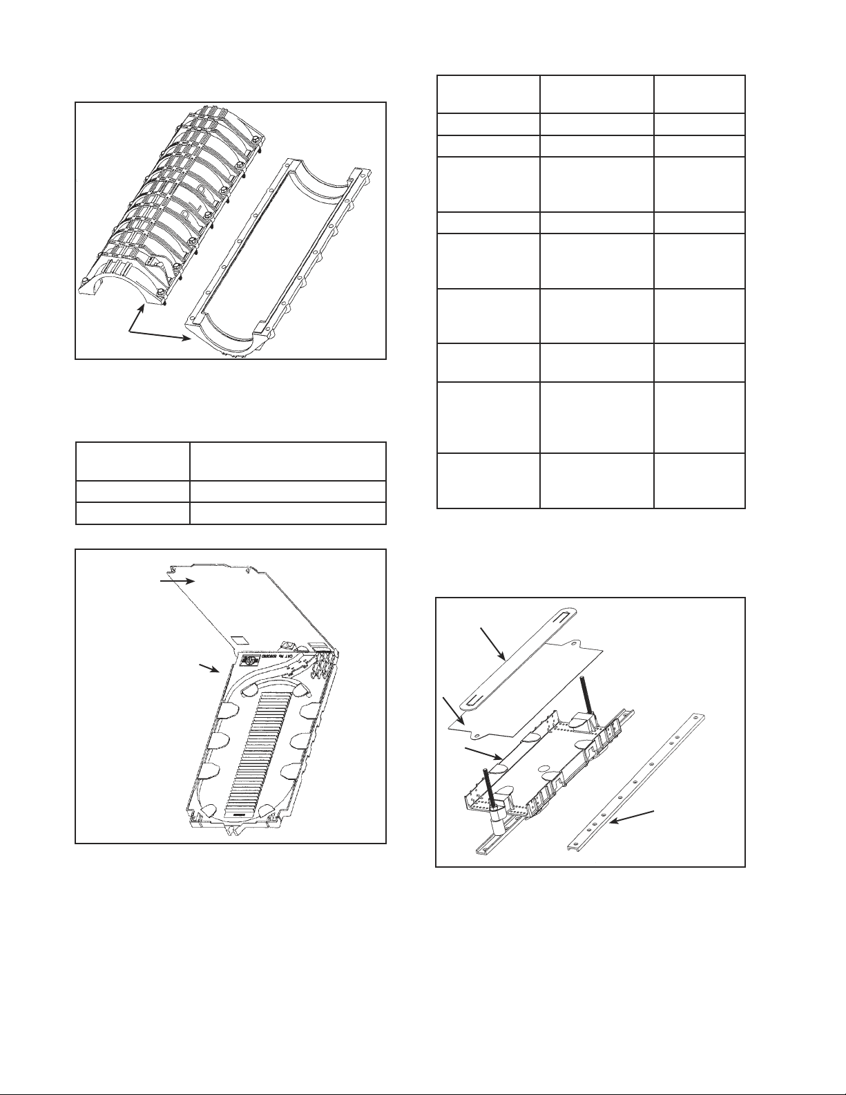
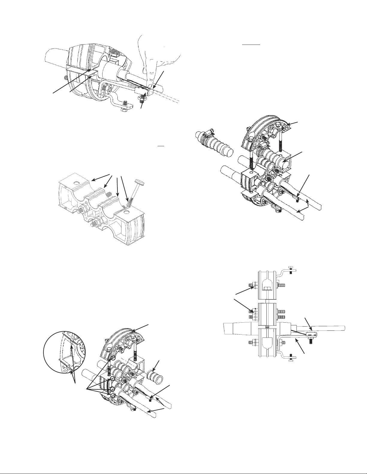
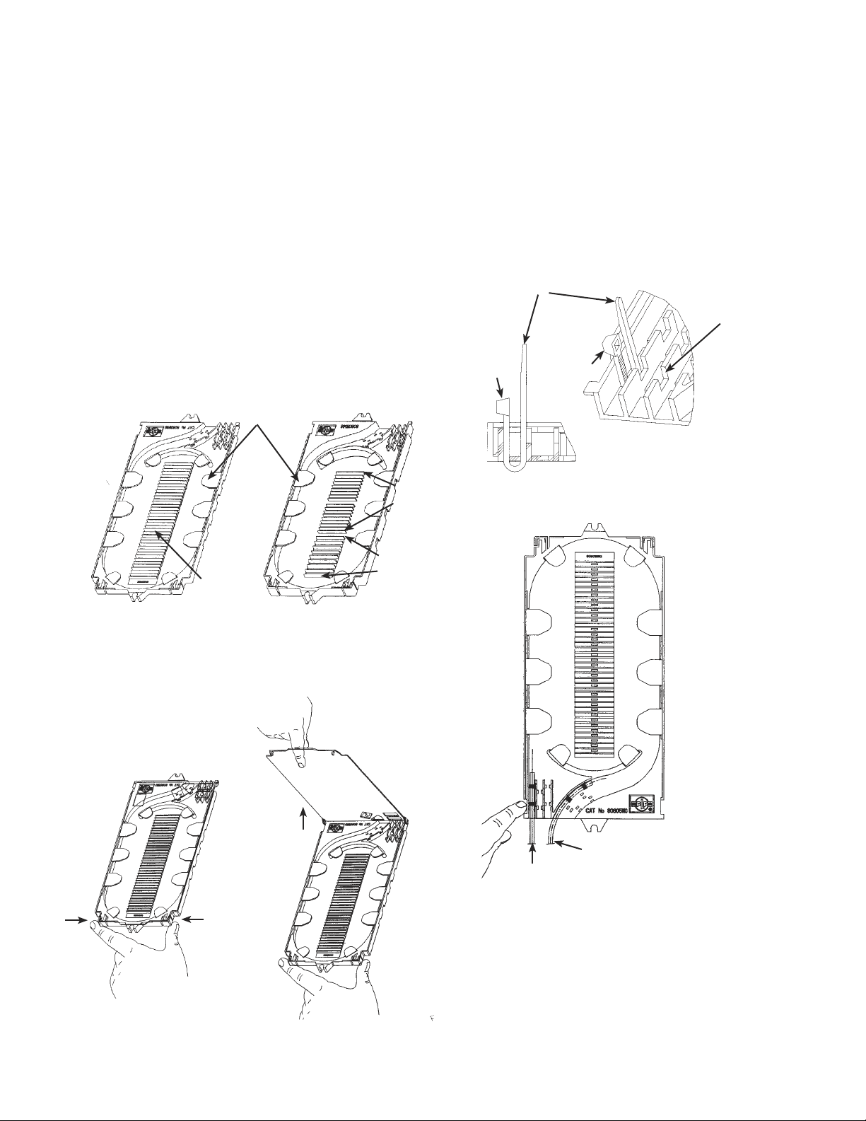
FIGURE 1 - SHELL KIT
1. Two COYOTE® Closure shell halves,
neoprene gasket is applied at factory.
1.00 NOMENCLATURE
1.
FIGURE 3 - UNITUBE TRANSITION
COMPARTMENT KIT
1.
2.
FIGURE 2 - SPLICE TRAY KIT
1. Cover
2. Tray
3. Splice Count Label (not shown)
4. Tie Wraps (not shown)
5. Felt Strips (not shown)
*Based on mass fusion splices; 96 for mass
mechanical.
PLP CATALOG
NUMBER
COYOTE CLOSURE
DIMENSIONS (CM)
80805258 6.0" x 22" (15.24 X 55.88)
80805259 8.5" x 22" (21.59 X 55.8)
1.
2.
3.
4.
PLP Catalog
Number
Splice
Tray
Splice
Capacity
80805110 Single Fiber Tray 36
80805509 Blank Tray 36
80805514 Blank Tray with
Three Elastomer
Splice Blocks
36
8001127 Low Profile Tray 12 per block
8001130 Low Profile
COYOTE Blank
Splice Tray
blank
80805146 Ribbon Fiber
Mechanical/
Fusion Tray
144*
80805510 Blank Ribbon
Tray
144*
80805515 Blank Ribbon
Tray with Two
Elastomer
Splice Blocks
144*
8003381 Elastomer
Splice Block Kit
- 3 per kit
12 per block
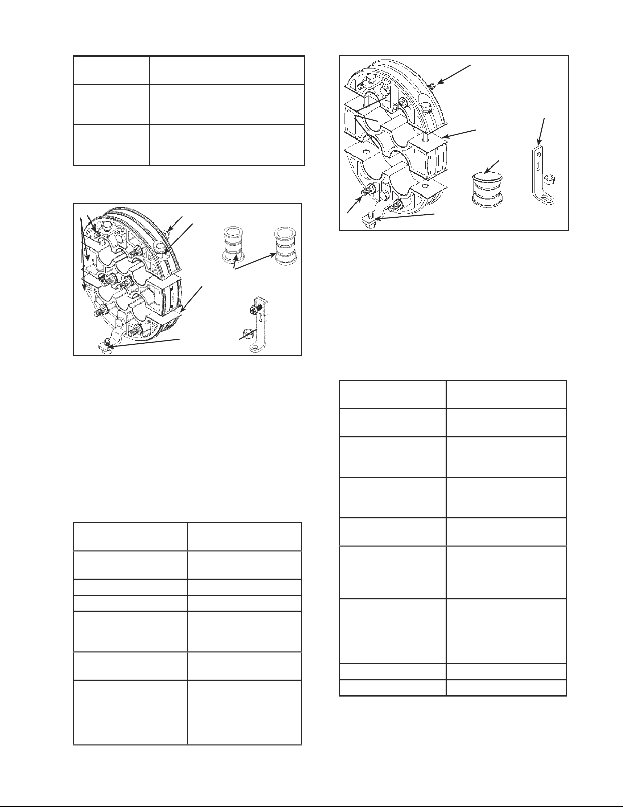
1. Splice Tray Hold 3. Transition Compartment
Down Strap 4. Torque Bar
2. Cover
3
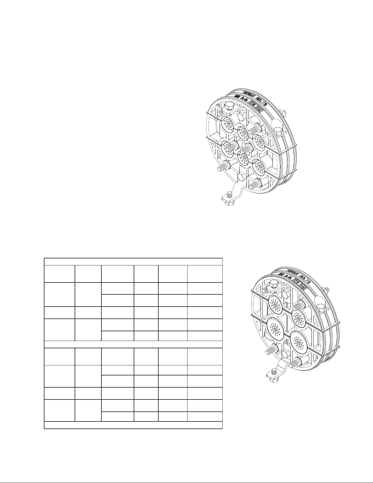
1. End Plate Sections
2. Torque Bar Brackets (2)
3. Plugs (5)
4. "L" Brackets (2)
5. LOCK-TAPE™ Sealant (factory-applied)
6. Internal Ground Inserts (6; factory-installed)
7. COYOTE Cable Mea-SURE™ Tape
(not shown)
PLP Catalog
Number
Description
80805112 6.0" x 22" (15.24 CM x 55.88
CM) Unitube Transition
Compartment Kit
80805113 8.5" x 22" (21.59.24 cm x 55.88
cm) Unitube Transition Compart-
ment Kit
FIGURE 4A - THREE-SECTION
SIX PORT END PLATE KIT
FIGURE 4B - THREE-SECTION
FOUR PORT END PLATE KIT
3.
1. End Plate Sections
2. Torque Bar Brackets (2)
3. Plugs (5)
4. "L" Brackets (2)
5. LOCK-TAPE™ Sealant (factory-applied)
6. Internal Ground Inserts (4; factory-installed)
7. COYOTE Cable Mea-SURE™ Tape (not
4.
1.
2.
2.
5.
6.
1. 2.
2.
3.
5.
6.
4.
PLP Catalog
Number
Description
80805105 Three-Section Six Port
End Plate Kit
80806037 3/4" plugs (2)
80806180 7/8" plugs (2)
8003371 Future Cable Port Kit
for 7/8” port (.56 max
cable diameter)
8003291 Future Cable
Installation Kit
8003289 Future Cable Port/
Installation Kit
(includes cat. no.
8003371 and cat. no.
8003291 for 7/8" port)
PLP Catalog
Number
Description
80805739 Three-Section Four Port
End Plate Kit
8003407 Future Cable Port Kit for
1" port (.81 max. cable
diameter)
8003409 Future Cable Port Kit
for 1-1/4" port (1" max.
cable diameter)
8003291 Future Cable Installation
Kit, only
8003408 Future Cable Port/
Installation Kit (includes
cat. no. 8003407 and cat.
no. 8003291 for 1" port)
8003410 Future Cable Port/
Installation Kit (includes
cat. no. 8003409 and
cat. no. 8003291 for
1-1/4" port)
80806038 1" plug (2)
80806181 1-1/4" plugs (2)

4
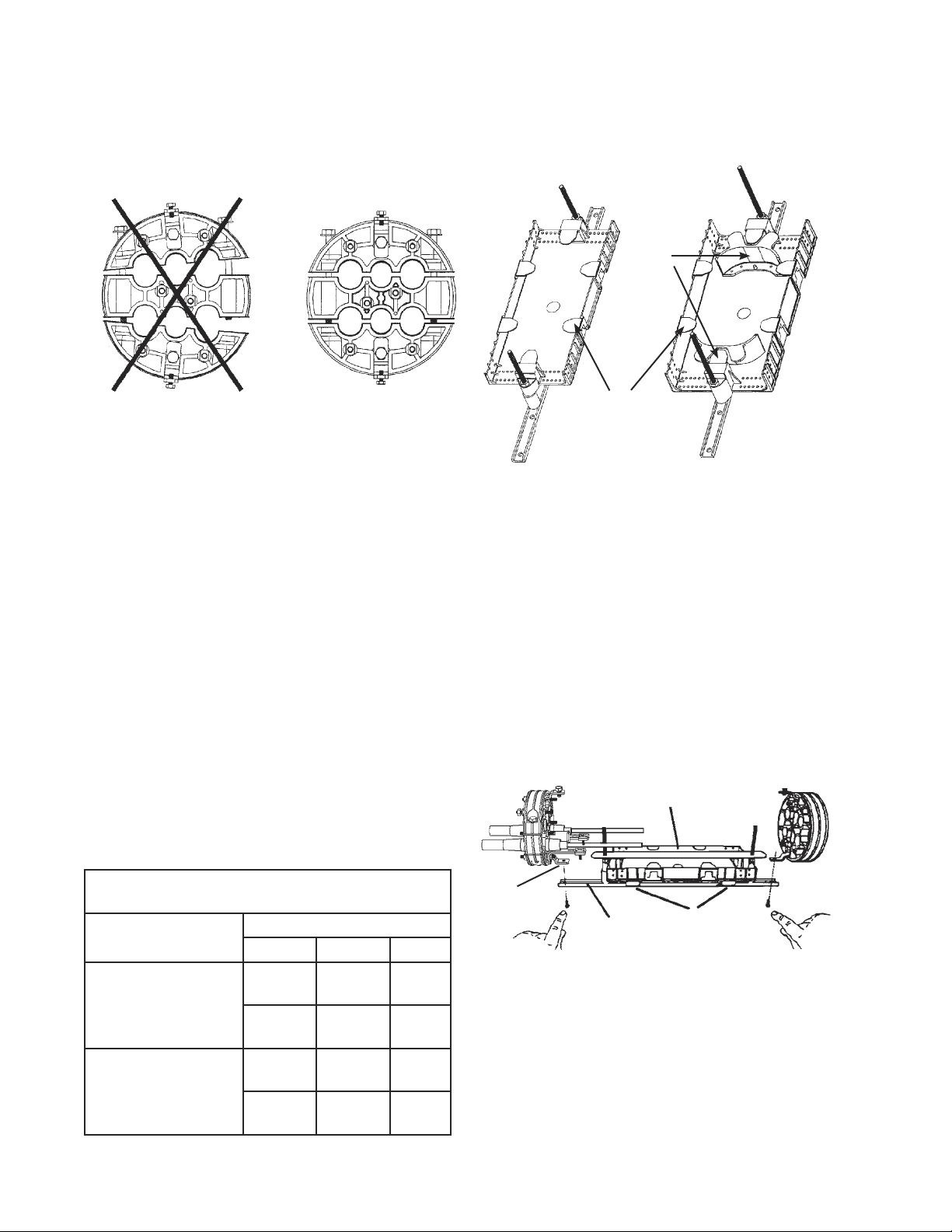
ACCESSORY KITS
1. End Plate
2. Torque Bar Brackets (2)
FIGURE 5 - BLANK END PLATE KIT
2.
1.
2.
1.
2.
3.
1. Torque Bar 3. Splice Tray Hold
2. Retainer Brackets Down Strap
FIGURE 6 - LOOSE BUFFER TUBE
STORAGE KIT
PLP Catalog Number Description
80805260 Blank End Plate Kit
PLP Catalog
Number
Description (cm)
80805262 6.0" x 22" (15.24 x 55.88) Loose
Buffer Tube Storage Kit
80805263 8.5"x 22" (21.59 x 55.88) Loose
Buffer Tube Storage Kit
80805419 6.0" x 22" (15.24 x 55.88)
COYOTE Express Organizer (for
loose buffer tube applications)
80805420 8.5" x 22" (21.59 x 55.88)
COYOTE Express Organizer (for
loose buffer tube applications)
PLP Catalog
Number
Description [cm]
8003285 Color-Coded Transport
Tube Kit (6 per kit)
80805293 Transport Tube Kit
(6 per kit)
80805107 Strength Member Bracket
Kit (2 per kit)
80805431 Long Strength Member
Bracket Kit (2 per kit)
8003280 Transition Tube Kit
8003281 External Bond Clip Kit
(2 per kit)
80805286 Bracket Adaptor Kit for
AT&T Bond Connector
(4 per kit)
8003325 Adjustable Aerial Hanger
Bracket Kit
80803448 Moisture Blocking Sealant
Kit (3 oz. tube)
80805238 C-Cement (1 oz tube)
8003279 Manhole Support
Bracket Kit
8003372 Vertical Mount Bracket Kit
(for 6.0" or 8.5" [15.24 x
21.59] COYOTE Closures)
8003322 Internal Ground Kit
(0.27" - 0.31" [.69 x .79]
ground wire)
8003360 Exterior Bond Braid kit
8003386 Heat Shield Kit for
6.0" x 22" [15.24 x 55.88]
COYOTE Closure
8003387 Heat Shield Kit for
8.5" x 22" [21.59 x 55.88]
COYOTE Closure
8003385 Flame-Retardant Blanket
for 6.0" x 22" [15.24 x
15.88] COYOTE Closure
8003388 Flame-Retardant Blanket
for 8.5" x 22" [21.59 x
55.88] COYOTE Closure
5
1.01 The COYOTE Closure contains every-
thing needed for installation except hand
tools, vinyl tape, filled cable cleaning fluid, and
C-Cement.
1.02 Tools Needed:
• 1/2" socket*
• 7/16" socket*
• 3/8" socket/Can wrench
• Snips
• Ratchet Wrench*
• Torque Wrench (capable of reading
50 inch lbs.)*
• Fiber optic cable opening tools
*Available from Preformed Line Products
2.00 DESCRIPTION AND CLOSURE
CAPACITIES
2.01 For Safety Considerations, refer to Section
21.00 of this procedure.
2.02 The COYOTE Closure series organizes,
distributes and protects all types of fiber
optic cable with a water and air tight seal.
2.03 The COYOTE Closure series accommo-
dates the following splice trays and splice
connectors (Table 1):
TABLE 1
3.00 END PLATE CONFIGURATIONS
3.01 Two versions of the Three-Section End
Plate are available for the COYOTE Clo-
sure; one which accepts up to six cables, and one
which accepts up to four larger cables. (Figures 7A
and 7B)
A = 7/8" (2.22 cm)
diameter
B = 3/4" (1.90 cm)
diameter
FIGURE 7A - DIAGRAM OF SIX PORT
END PLATE
A = 1" (2.54 cm)
diameter
B = 1-1/4" (3.18 cm)
diameter
FIGURE 7B - DIAGRAM OF
FOUR PORT END PLATE
A
A
B
B
A
A
B
6.0" X 22" (15.24 cm x 55.88 cm) COYOTE Closure
Splice Tray
Catalog
Number
Description Usable
Connectors
Splice
Capacity
Per Tray
Maximum No.
of Trays Per
Closure
Maximum
Closure Splice
Capacity
80805110 or
80805514
36 Count
Single Fiber
Tray
Single Fusion 36 4 144
Single
Mechanical
36 4 144
8001127 Low Profile
Tray
Single Fusion 36 6 216
80805146 96 Count
Mass
Ribbon
Fiber Tray
Mass
Mechanical*
96 2 192*
Mass Fusion* 144 2 288*
8.5" X 22"(21.59 cm x 55.88 cm) COYOTE Closure
Splice Tray
Catalog
Number
Description Usable
Connectors
Splice
Capacity
Per Tray
Maximum No.
of Trays Per
Closure
Maximum
Closure Splice
Capacity
80805110 or
80805514
36 Count
Single Fiber
Tray
Single Fusion 36 8 288
Single
Mechanical
36 8 288
8001127 Low Profile
Tray
Single Fusion 36 11 396
80805146 96 Count
Mass
Ribbon
Fiber Tray
Mass
Mechanical*
96 4 384*
Mass Fusion* 144 4 576*
* Assumes 12 fiber ribbon is utilized. Also holds 16 single count splices.
A
A
B

6
3.02 See Figure 8 for hardware that can be used
with the Three-Section End Plate.
4.00 CABLE PREPARATION–LOCK-
TAPE SEALANT APPLICATION
NOTE: For OPGW application, see procedure en-
titled, “OPGW Cable and End Plate Preparation
for COYOTE® Closure” (SP2849).
4.01 Cable sheath opening measurements, for
both size closures, whether using unitube or
buffer tube, are 152" (386.10 cm) for continuous
loop/express applications, and 76" (193.04 cm)
for cut cable.
NOTE: The COYOTE Closure is designed for main
cables to enter the bottom outside cable ports
and for branch cables to enter the bottom middle
and upper cable ports in the End Plate.
PLP TIP: Where irregular cable ends exist, measure
from the shortest cable to establish End Plate
location.
4.02 The color-coded COYOTE Cable Measure
Tapes are used to determine the number of
half-lapped layers of LOCK-TAPE Sealant required
to seal the cable in the End Plate. The back of the
Measure Tape is used to check whether the LOCK-
TAPE Sealant wrap is the proper diameter to ensure
a water and air tight seal. (Figure 9)
For the Six Port End Plate, the orange-colored end is
used to measure cables entering the 7/8" (2.22 cm)
FIGURE 8 - END PLATE HARDWARE
diameter ports while the blue-colored end measures
cables entering the 3/4" (1.90 cm) diameter ports.
For the Four Port End Plate, the COYOTE Cable
Measure Tape has a green-colored end for the 1"
diameter port and a red-colored end for the 1-1/4"
diameter port.
FIGURE 9 - COYOTE CABLE MEASURE TAPE
(TAPE FOR SIX PORT END PLATE SHOWN)
4.03 TO USE COYOTE CABLE MEASURE
TAPE:
• Wrap the correct end of COYOTE Cable
Measure Tape around cable where it will
enter the End Plate.
• If the index line falls directly between two
numbers use the higher number.
• The number on the COYOTE Cable Mea-
sure Tape indicates the number of half-
lapped layers of LOCK-TAPE Sealant to be
applied around the cable. (Figure 10)
FIGURE 10 - MEASURING CABLE --
BE SURE TO USE CORRECT END OF CABLE
MEASURE TAPE
"L" BRACKET
BOLT
HEAD-
TOP
BOLT-
BOTTOM
INTERNAL
GROUND
INSERTS
FOR EACH
PORT
STRENGTH
MEMBER
CAP
TORQUE BAR
BRACKET
BLUE
BLUE
ORANGE
ORANGE
7
FIGURE 13 - CHECK GAUGE
4.08 To protect LOCK-TAPE Sealant from cable
grease, cover the LOCK-TAPE Sealant with
vinyl tape.
NOTE: If strength members are to be secured, leave
4-5" (10.16-12.70 cm) of metallic or non-metal-
lic strength members exposed from the sheath
opening.
4.09 Open and clean cable according to accepted
company practices.
5.00 INTERNAL BOND PROCEDURE
5.01 Bond cable according to accepted company
practices. Use the slot on the "L" bracket to
attach most bond connectors, as outlined in Section
8.00. (Figure 14)
FIGURE 14A - SLOT IN "L" BRACKET
4.07 To check LOCK-TAPE Sealant application,
wrap the proper end of the COYOTE Cable
Measure Tape check gauge around the applied
LOCK-TAPE Sealant. If the measurement line falls
outside of the index lines of the check gauge, LOCK-
TAPE Sealant must be reapplied. It is acceptable to
reapply the original LOCK-TAPE Sealant. (Figure 13)
SLOT
4.04 Using the provided Emery Cloth, thoroughly
scuff the cable sheath for 5" (12.70 cm) from
measured opening. Always scuff around the cable,
never lengthwise.
4.05 Coat the scuffed area with C-Cement and
allow to dry. It is important that the C-Cement
dries to a tacky base before LOCK-TAPE Sealant is
applied.
PLP TIP: Use removed LOCK-TAPE Sealant backing
from Step 4.06 to dry and remove excess C-Ce-
ment applied to cable.
4.06 Remove backing from LOCK-TAPE Sealant
and wrap LOCK-TAPE Sealant onto the
cable with the black side up. Stretch the 1" (2.54 cm)
LOCK-TAPE Sealant to a width of 7/8" (2.22 cm).
(Figure 11) Apply the required numbers of half-
lapped layers of LOCK-TAPE Sealant, as indicated
on the Cable Measure Tape, to the area coated with
C-Cement. (Figure 12)
FIGURE 11 - STRETCH LOCK-TAPE
FIGURE 12 - APPLIED LOCK-TAPE
1" (2.54 cm)
7/8" (2.22 cm)

8
FIGURE 15A - ATTACH "L" BRACKET–
FRONTAL VIEW
FIGURE 15B - ATTACH "L" BRACKET–SIDE VIEW
7.02 Remove the protective vinyl tape applied to
LOCK-TAPE Sealant in Paragraph 4.08.
7.03 Place the cable into the End Plate as close to
the assembly location as possible. Mark it
1/4-1/2" (.64-1.27 cm) from the outside surface of the
End Plate. Apply vinyl tape over the remaining LOCK-
TAPE Sealant. Do not apply vinyl tape in the seal
area.
7.04 Use the strength member cap on the "L"
bracket as a guide for trimming the strength
member. (Figure 16)
PLP TIP: A long "L" bracket is available (Catalog
#80805431) for bonded loose buffer tube cable
with a dielectric central strength member.
FIGURE 14B - LONG "L" BRACKET
6.00 END PLATE PREPARATION
6.01 Disassemble the End Plate by removing the
two long bolts holding the three End Plate
sections together. Remove the packaging plugs.
6.02 Refer to Table 2 for the measurement of
sheath to extend beyond the inside of the
End Plate for the type of cable and bond connector
being used. For all non-metallic cables the sheath will
extend 3/4" (1.90 cm) inside the End Plate.
Cable Positions In COYOTE Closure End Plate
Cable Type If using
Bond
Connectors
Length of Sheath
Inside End Plate (cm)
Dielectric 3/4" (1.90)
Metallic RAYCHEM* 1-1/4" (3.18)
AT&T* Total 1-3/8" (3.47) =
5/8" (1.57) shield +
3/4" (1.90) sheath
*See Accessory Kits for additional bond hardware
TABLE 2
7.00 END PLATE ASSEMBLY
7.01 Loosely attach "L" brackets to the ground
insert on the inside of the End Plate adjacent
to the cable ports being used with the nut provided.
(Figure 15 A & B)
INTERNAL
GROUND
INSERT
BOLT
HEAD-
TOP
EXTERNAL
GROUND
INSERT--
DOUBLE-NUTTED
"L" BRACKET
BOLT-
BOTTOM
STRENGTH
MEMBER
CAP
"L" BRACKET
BOLT
HEAD-
TOP
BOLT-
BOTTOM
INTERNAL
GROUND
INSERTS
FOR EACH
PORT
STRENGTH
MEMBER
CAP
MAIN
CABLE
PORT
ENTRY
9
FIGURE 16 - CAP AS TRIMMING GAUGE
7.05 Remove cable from the End Plate port(s) and
apply C-Cement along the edge of all End
Plate ports. Make sure C-Cement is dry before con-
tinuing. The End Plate center section is illustrated in
Figure 17.
FIGURE 17 - APPLY C-CEMENT
7.06 Lay prepared cable and correct end of
appropriate plugs into ports and loosely
tighten all three sections of End Plate. Use care that
no grease from the cable contacts the LOCK-TAPE
Sealant on the End Plate ports. (Figure 18)
PLP TIP: Use orientation marks on End Plate as
alignment guide. (See Figures 18 & 19)
7.07 Future cable entry ports and End Plate
grommets cannot be added once End Plate
assembly is complete. Therefore, when using future
cable entry ports, insert ports at this time. Future
cable entry ports will fit in only the 7/8" ports of the
Six Port End Plate, and different future cable entry
ports are available for both the 1" ports and the 1-1/4"
ports in the Four Port End Plate (see page 3 for de-
tails). Also see the Application Procedure accompa-
nying the Future Cable Entry Port Kits and End Plate
Grommet Kits. (Figure 19)
FIGURE 19 - INSTALLED FUTURE CABLE
ENTRY PORTS (SIX PORT END PLATE)
7.08 Slide strength members under cap and
tighten. Tighten "L" bracket. (Figure 20)
FIGURE 20 - INSTALLING STRENGTH MEMBER
A = 7/8" (2.22 CM) B = 3/4" (1.90 CM)
A
A
B
C-Cement
FIGURE 18 - INSTALLED CABLE AND PLUGS
(SIX PORT END PLATE)
INSIDE SURFACE
OF END PLATE
DOUBLE
NUTTED
CAP
"L" BRACKET
OUTSIDE SURFACE
OF END PLATE
PREPARED
CABLE
CAP
INSIDE
SURFACE
OF END PLATE
FUTURE
CABLE ENTRY
PORT
INSIDE SURFACE
OF END PLATE
PLUG
PREPARED
CABLE
CAP
ORIENTATON
MARKS
CUT
STRENGTH
MEMBER
HERE
CAP
ORIENTATION
MARKS
10
9.00 INSTALLING TRANSITION COM-
PARTMENT FOR UNITUBE CABLE
9.01 See Figure 22 for the features of the transi-
tion compartments.
6.0" x 22" 8.5" x 22"
(15.24 cm x 55.88 cm) (15.24 cm x 55.88 cm)
TRANSITION COMPARTMENT TRANSITION COMPARTMENT
--SINGLE FIBER --SINGLE OR RIBBON FIBER
FIGURE 22 - TRANSITION COMPARTMENTS
9.02 The transition compartment assembly
attaches to the torque bar bracket on the bot-
tom of the end plates with the bolts provided. (Figure
23) Make sure the side of the torque bar labelled "3
Section End" is nearest the Three-section End Plate.
The torque bars are labelled for in-line as well as butt
installation.
FIGURE 23 - INSTALL TRANSITION
COMPARTMENT
9.03 Remove splice tray hold down strap and
transition compartment cover. (Figure 24A)
7.09 When all cables and/or plugs have been
installed, tighten End Plate bolts by rotating
2 or 3 turns on each bolt so the End Plates come
together evenly. Tighten bolts with torque wrench to
150 inch pounds. (Figure 21)
FIGURE 21 - CORRECT END PLATE ALIGNMENT
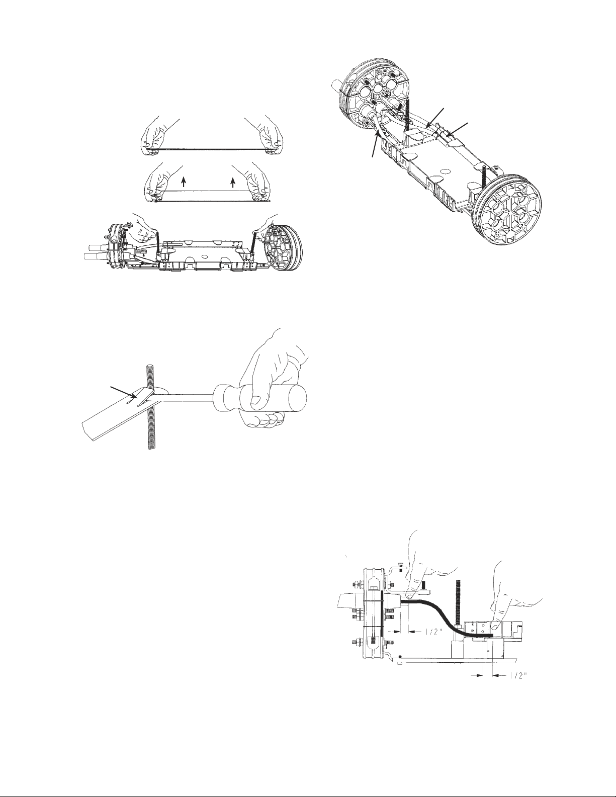
7.10 Apply vinyl tape to the remaining 1/4–1/2"
(.64-1.27 cm) (Paragraph 7.03) of exposed
LOCK-TAPE Sealant on the cable outside the End
Plate.
8.00 UNITUBE PREPARATION
8.01 For unitube cable refer to Table 3 to
determine the correct length of core tube
necessary to enter the transition compartment when
using the lower cable ports in the End Plate. Cables
entering the upper ports will be transitioned into the
compartment using a transition tube. Refer to Para-
graph 10.02 for core tube lengths. See Section 14.00
for routing loose buffer tube cable into the storage
compartment. When routing both unitube and buf-
fer tube in the same closure, follow instructions for
unitube application.
Unitube Lengths (cm) From Sheath
to Transition Compartment
COYOTE Closure
Dimensions
Splice Configurations
In-Line Butt
6.0" x 22"
(15.24 x 55.88)
Top 3/4"
(1.91)
3/4"
(1.91)
Bottom 5-3/4"
(13.97)
6"
(15.24)
8.5" x 22"
(21.59 x 55.88)
Top 3/4"
(1.91)
3/4"
(1.91)
Bottom 6"
(15.24)
6-3/4"
(16.51)
TABLE 3
INCORRECT CORRECT
TORQUE BAR
BRACKET
TORQUE BAR
TRANSITION
COMPARTMENT
ASSEMBLY
CLIPS FOR
ROUTING
LOOSE BUFFER
TUBES
REMOVE
TABS WHEN
STORING
FIBERS
REMOVABLE
RETAINING
TABS
11
FIGURE 25 - SECURING CABLE TUBE
10.02 Unitube cables entering through the top
ports of the End Plate will require a transition
kit (Catalog # 8003280). The kit includes two lengths
of tube approximately 24" (60.96 cm) long which can
be field cut 7"-8". The smaller transition tube (.240"
[.610 cm] diam.) is for unitube cables ranging from 4-
48 fiber count. The larger transition tube (.311" [.790
cm] diam.) is for unitube cables ranging from 50-96
fiber count.
10.03 Leave approximately 3/4" (1.90 cm) of cable
tube for all cables entering the top ports of
the End Plate. Determine which diameter transition
tube is to be used. To measure the correct amount of
transition tube necessary, hold it 1/2-3/4" (1.27-1.90
cm) past the unitube, make an "S" bend into the tran-
sition compartment 1/2" (1.27 cm) past the tie down
ports in the bottom of the tray. Cut the transition tube
at this mark and apply. (Figure 26)
FIGURE 26 - MEASURING TRANSITION TUBE
PLP TIP: Install fibers in transition tube, then apply
moisture blocking compound.
PLP TIP: If the hold down strap is snug against the
studs, lift the tab using a screwdriver as demon-
strated in Figure 24B.
FIGURE 24A - REMOVE SPLICE TRAY HOLD
DOWN STRAP AND COVER
FIGURE 24B - HOLD DOWN STRAP REMOVAL
10.00 SECURING UNITUBE IN THE
TRANSITION COMPARTMENT
NOTE: Prior to installing unitube cable, apply mois-
ture blocking sealant (Catalog #80803448) into
the end of the tube according to your company or
cable manufacturer's practices.
10.01 Secure unitube to the transition compartment
as shown in Figure 25.
NOTE: It is important that all single cable tubes are
secured in the correct position on the transition
compartment.
MAIN
CABLE
BOTTOM
MIDDLE
CABLE
MAIN CABLE
TAB
LIFT
12
10.04 Wrap the end of the transition tube with one
layer of the felt tape provided and secure to
the bottom of the transition compartment with two of
the tie wraps provided. (Figure 27)
FIGURE 27 - SECURING TRANSITION TUBE FOR
CABLES ENTERING TOP END PLATE PORTS
11.00 ROUTING AND STORING FIBER IN
THE TRANSITION COMPARTMENT
11.01 When routing fiber in the transition compart-
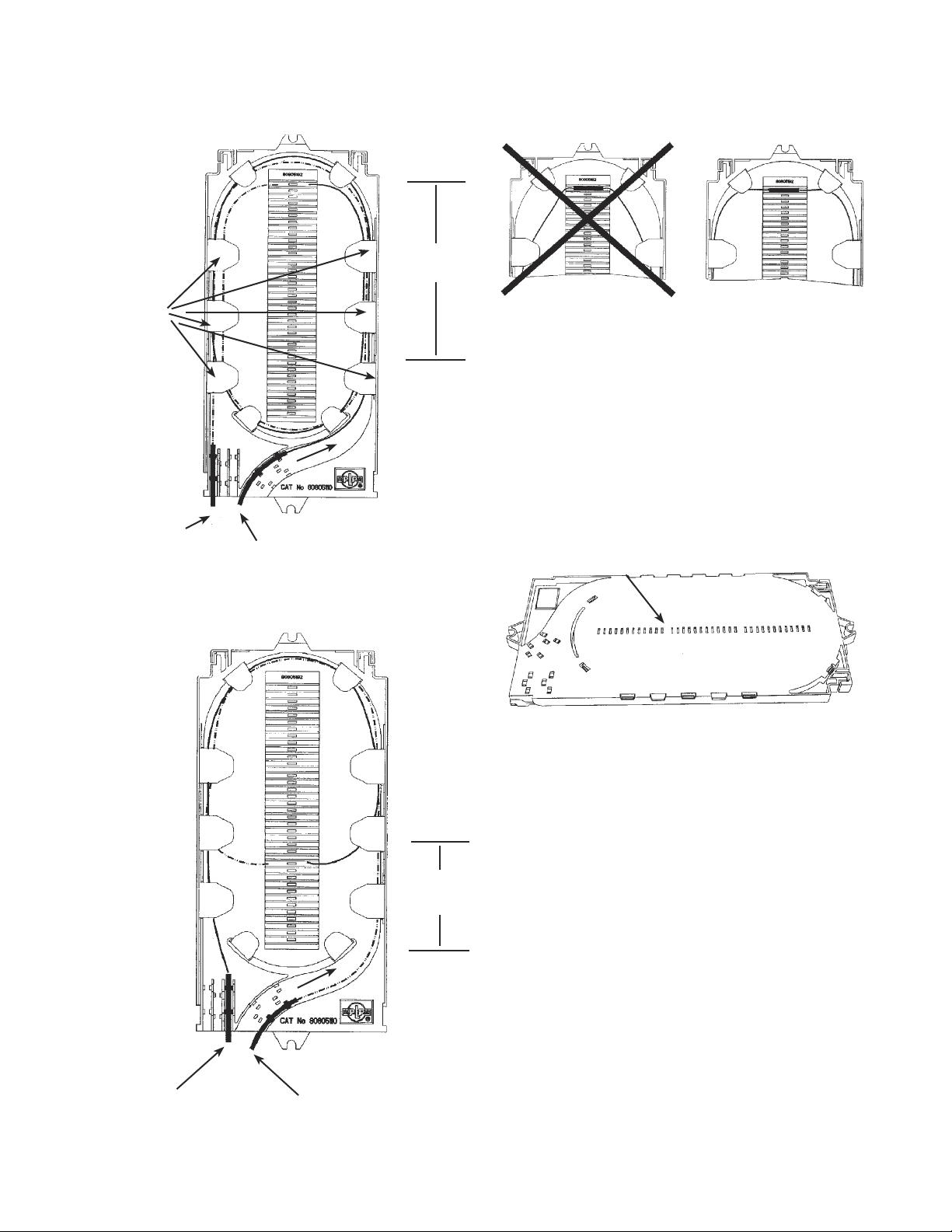
ment of either size closure for continuous
loop applications, cut the fibers to be spliced at the
midpoint of the loop. This allows for splicing in either
direction. Lay the fibers to be spliced directly through
the transition compartment exiting the opposite end.
These fibers will be routed to splice trays 1-4 of the
6.0" x 22" (15.24 cm x 55.88 cm) and trays 1-8 of
the 8.5" x 22" (21.59 cm x 55.88 cm) via transport
tubes. Wrap the continuous loop, and the fibers not
being spliced, until all fibers are stored in the transi-
tion compartment. For cut cables bring all fibers to be
spliced directly through the transition compartment
exiting the opposite end of the same corner
(Figure 28).
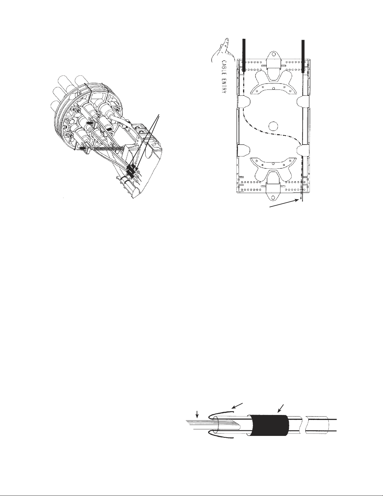
FIGURE 28 - ROUTE FIBERS IN TRANSITION
COMPARTMENT – 6.0" X 22" AND 8.5" X 22"
12.00 INSTALLING FIBERS INTO
TRANSPORT TUBES AND
SECURING TO TRANSITION
COMPARTMENT
12.01 Group fibers into bundles determined by how
many fibers will be inserted into each trans-
port tube. A maximum of six transport tubes can be
terminated per splice tray.
12.02 Push fibers through the transport tubes.
NOTE: For ribbon fiber application, fiber guide wires
are provided. Suggested use is four ribbons per
tube. (Figure 29)
FIGURE 29 - GUIDE WIRES IN USE
RIBBON
FIBER
FELT
FIBER
GUIDE
WIRE
FELT
EXIT POINT FOR FIBERS
TO BE SPLICED

13
12.03 Select the required number of transport
tubes and wrap one layer of felt tape 1/2"
(1.27 cm) from one end of all transport tubes.
(Figure 30)
FIGURE 30 - WRAP FELT TAPE
NOTE: Fiber from transition compartment enters at
felt tape end of transport tube.
12.04 Repeat steps 12.01 through 12.03 for re-
maining transport tubes.
PLP TIP: To differentiate between the office and field
side, place vinyl tape at the end of one set of
transport tubes.
12.05 Secure all transport tubes with the felt tape
applied to the inside tie down holes in the
transition compartment with two of the tie wraps pro-
vided. (Figure 31)
FIGURE 31 - SECURE TRANSPORT TUBES
PLP TIP: For ease of handling, group the transport
tubes in multiples of six. This simplifies the ar-
rangement of the final group of transport tubes in
the transition compartment. (Figure 32 A & B)
FIGURE 32A - GROUP TRANSPORT
TUBES-SINGLE CLUSTER
FIGURE 32B - GROUP TRANSPORT TUBES-
MULTIPLE CLUSTERS
12.06 Replace protective cover on transition
compartment as in Figure 33.
FIGURE 33 - REPLACE COVER
1/2"
FELT
FIBER ENTRY POINT
EXIT POINT
FOR FIBERS
TO BE
SPLICED
14
13.03 Position the transport tubes onto the splice
tray so they extend 1/4" (.64 cm) past the tie
down holes and apply provided tie wraps as shown in
Figures 36 A & B.
PLP TIP: For easy tie wrap installation, insert the
tie wrap with the ridges on the inside of the loop,
with the head opposite the notch in the splice
tray. Insert the tail into the head. Press head
down to the tray and hold in place while pulling
the tail to tighten the tie wrap.
FIGURE 36A - SECURE TIE WRAPS
FIGURE 36B - POSITION AND SECURE
TRANSPORT TUBES
13.04 When routing the fiber in the SINGLE
COUNT SPLICE TRAY, route fibers 1-24
1-1/2 times around the splice tray and lay into
the top of the splice block (see Figure 37A). Route fi-
bers 25-36 1-3/4 times around the splice tray, and lay
into the bottom of the splice block (see Figure 37B).
13.00 SECURING TRANSPORT TUBES
AND ROUTING FIBER IN SPLICE
TRAYS
13.01 There are six types of splice trays available
for the COYOTE Closure. The single fiber
trays are designed for single fusion or single me-
chanical splice applications. The single fiber trays can
accommodate up to 36 single fiber splices. The mass
fiber trays are designed for 12 mass fusion or 8 mass
mechanical splices. (Figure 34) Refer to Table 1 for
COYOTE Splice Tray capacities.
Single fiber Splice Tray (Cat. No. 80805514) consists
of a bare splice tray and three self-stick elastomer
(12-count) splice blocks. Follow the procedures
included with this splice tray to position the splice
blocks on the tray.
SINGLE FIBER TRAY MASS FIBER TRAY
FIGURE 34 - SPLICE TRAYS
13.02 Remove cover of splice tray. (Figure 35)
FIGURE 35 - REMOVE SPLICE TRAY COVER
NOTCH
TAIL
HEAD HEAD
FIELD
OFFICE
REMOVABLE
RETAINING TABS
36
SINGLE
FIBER
SPLICES
12
MASS
FUSION
SPLICES
8
MASS
MECHANICAL
SPLICES
PRESS
LIFT
15
13.05 Splice the fibers according to your accepted
company practices. (Figure 38)
FIGURE 38 - BEND RADIUS - IMPORTANT
PLP TIP: If splice protectors loosely fit in the slots
of the splice block, wrap each protector with felt
tape to provide the desired fit or use a bead of
silicone caulk to secure the connectors and place
a strip of felt tape over the connectors and sili-
cone caulk. Place Splice Count Label on cover to
identify fibers spliced. On the back of both trays,
slots are provided to aid in the removal of splice
protectors or connectors. (Figure 39)
FIGURE 39 - SPLICE BLOCK SLOTS
NOTE: There should be a minimum of 50" (127 cm)
of exposed fiber for splicing.
FIGURE 37A - ROUTING FIBERS IN THE
SINGLE FIBER SPLICE TRAY–FIBERS 1-24
FIGURE 37B - ROUTING FIBERS IN THE
SINGLE FIBER SPLICE TRAY–FIBERS 25-36
SLOTS
OFFICE
FIELD
SLOTS
1-24
FOR
EASE OF
ACCESS
DURING
SPLICING,
TABS
MAY BE
REMOVED
SLOTS
25-36
OFFICE FIELD

16
FIGURE 41 - ROUTING FIBERS IN THE
MASS FIBER SPLICE TRAY FOR MASS FUSION
13.08 Splice fibers according to accepted company
practices. (Refer back to Figure 38)
PLP TIP: If splice protectors loosely fit in the slots
of the splice block, wrap each protector with felt
tape to provide the desired fit or use a bead
of silicone caulk to secure the connectors and
place a strip of felt tape over the connectors and
silicone caulk.
13.09 Replace all tray retaining tabs.
13.10 To replace tray cover, position pivotal arm on
plastic cover underneath the hinges on the
splice tray and snap into place. (Figure 42)
FIGURE 42 - REPLACE SPLICE TRAY COVER
13.06 When routing the fiber in the MASS FIBER
SPLICE TRAY for MASS MECHANICAL,
route fibers 1-1/2 times around the splice tray and lay
into the top of the splice block. (Figure 40)
NOTE: There should be a minimum of 50" (127 cm)
of exposed fiber for splicing.
FIGURE 40 - ROUTING FIBERS IN THE MASS
FIBER SPLICE TRAY FOR MASS MECHANICAL
13.07 When routing fibers in the MASS FIBER
SPLICE TRAY for MASS FUSION, route
fiber 1-3/4 times around the splice tray and lay into
the splice block. (Figure 41)
HINGE
MASS
MECHANICAL
SPLICE BLOCK–
8 POSITIONS
FIELDOFFICE
FIELD
OFFICE
MASS
FUSION
SPLICE BLOCKS–
16 POSITIONS
(USE 12
POSITIONS
MAXIMUM FOR
MASS FUSION
SPLICES)
17
13.13 Install the top torque bar to the upper torque
bar brackets on the end plates with the
bolts provided. (Figure 45) Make sure the side of the
torque bar labelled "3 Section End" is nearest the
Three-section End Plate. The torque bars are labelled
for in-line as well as butt installation.
FIGURE 45 - INSTALL TOP TORQUE BAR
13.14 See Section 15.00 for installing COYOTE
Closure Shells.
14.00 ROUTING LOOSE BUFFER TUBE
CABLE
14.01 When routing both unitube and buffer tube in
the same closure, follow instructions for
unitube application beginning in Paragraph 8.00. For
buffer tube alone, install the loose buffer tube storage
compartment (Figure 46A) or express loose buffer
tube storage compartment (Figure 46B) to the torque
bar bracket on the bottom of the End Plates with the
bolts provided. Make sure the side of the torque bar
labelled "3 Section End" is nearest the Three-section
End Plate. The torque bars are labelled for in-line as
well as butt installation.
FIGURE 46A - INSTALL LOOSE BUFFER TUBE
STORAGE COMPARTMENT
13.11 Slide all splice trays onto the threaded studs.
See Figures 43 A & B for proper splice tray
alignment for the 6.0" x 22" (15.24 cm x 55.88 cm)
closure and the 8.5" x 22" (21.59 cm x 55.88 cm)
closure.
FIGURE 43A - PROPER SPLICE TRAY
ALIGNMENT 6.0" X 22" (15.24 CM X 55.88 CM)
FIGURE 43B - PROPER SPLICE TRAY ALIGNMENT
8.5" X 22" (21.59 CM X 55.88 CM)--TRAYS 1-8
13.12 After all splices are completed, secure all
splice trays onto the threaded studs by reap-
plying the splice tray hold down strap. (Figure 44)
FIGURE 44 - REPLACE SPLICE TRAY HOLD
DOWN STRAP
3-SECTION
END PLATE
TRAYS 1-8
3-SECTION
END PLATE
TRAYS 1-4

18
ROUTING STORING
FIGURE 48 - LOOSE BUFFER TUBE ROUTING
AND STORAGE
14.04 Position the trays on the threaded studs.
There should be a minimum of 50" (127 cm) of
exposed fiber for splicing in the tray. Lay the loose
buffer tubes in the tray and make a mark on the tube
1/4" (.64 cm) past the tie down holes. See Figure 49.
Remove the loose buffer tube from this point outward.
Clean exposed fibers according to accepted com-
pany practices.
FIGURE 49 - LAY TUBES IN TRAY AND MARK
STUDS
FIGURE 46B - INSTALL EXPRESS LOOSE BUF-
FER TUBE STORAGE COMPARTMENT
14.02 Remove splice tray hold down strap.
(Figure 47A)
PLP TIP: If the hold down strap is snug against the
studs, lift the tab using a screwdriver as demon-
strated in Figure 47B.
FIGURE 47A - REMOVE SPLICE TRAY HOLD
DOWN STRAP
FIGURE 47B - HOLD DOWN STRAP REMOVAL
NOTE: See Table 1 for COYOTE Splice Tray capaci-
ties.
14.03 When routing loose buffer tubes in the 6.0" x
22" (15.24 cm x 55.88 cm) and 8.5" x 22"
(21.59 cm x 55.88 cm) COYOTE Closure. Route the
loose buffer tubes to be spliced through the storage
compartment, exiting them both at the opposite end
on the same side. Store any unspliced loose buffer
tubes or continuous loop loose buffer tubes by routing
them inside the storage brackets. (Figure 48)
MARK
➔
THREE-SECTION
END PLATE
SIDE
FIBERS FROM
STORAGE
COMPARTMENT
MINIMUM
50" (127 CM)
EXPOSED
FIBER
TAB
EXIT POINT
FOR FIBERS
TO BE
SPLICED
19
FIGURE 50B - POSITION AND SECURE
TRANSPORT TUBES
14.11 For routing the fiber in the SINGLE FIBER
SPLICE TRAY, see Paragraph 13.04.
14.12 For routing fibers in the MASS FIBER
SPLICE TRAY, see Paragraphs 13.07 and
13.08.
14.13 To replace splice tray cover, splice tray hold
down strap and torque bar see Paragraphs
13.10-13.13.
15.00 INSTALLING THE COYOTE
CLOSURE SHELLS
15.01 The neoprene in the shells must be pliable
when installed. In cold weather (below 32˚ F),
for new installation, or re-entry, warm shells prior to
installation.
15.02 Remove protective paper liners from shells.
Take care to keep gasket area clean.
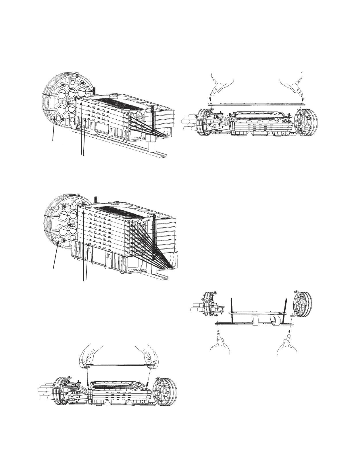
15.03 The top and bottom shells are mated to-
gether around the End Plates. The top shell
is identified by an air valve and bolts. Position the
top and bottom shells around the End Plates in the
grooves located in each shell half.
14.05 COYOTE Express Closure Application:
The COYOTE Express Closure is designed
for loop or ring application where a high count fiber
is used and a continuous loop or express splice is
made and a low count branch cable is being spliced.
More room in the storage compartment is required
for the storage of slack buffer tube.
14.06 Follow Paragraph 4.01 for cable opening
measurements.
14.07 Separate the buffer tubes to be spliced from
the rest of the express buffer tubes and cut
them at the center points.
14.08 From the left entrance, start wrapping the
express fiber to be stored in a clockwise
rotation until all express buffer tubes are stored in the
express storage compartment.
14.09 Route buffer tubes to be spliced to the splice
trays.
NOTE: The express storage compartments accept
two single splice trays in the 6.0" COYOTE
Express Closure and four single trays in the 8.5"
closure.
14.10 Place one wrap of felt tape at the end of
each loose buffer tube. Position the buffer
tubes onto the splice tray so they extend 1/4" (.64)
past the tie down holes and apply provided tie wraps
as shown in Figures 50 A & B.
PLP TIP: For easy tie wrap installation, insert the
tie wrap with the ridges on the inside of the loop,
with the head opposite the notch in the splice
tray. Insert the tail into the head. Press head
down to the tray and hold in place while pulling
the tail to tighten the tie wrap.
FIGURE 50A - SECURE TIE WRAPS
NOTCH
TAIL
HEAD
HEAD
FIELD
OFFICE
20
16.00 EXTERNAL BOND PROCEDURE
16.01 For all ground inserts with cables attached,
loosely attach a bond clamp (2 per kit) (Cata-
log #8003281) outside the End Plate. The clamp
attaches between the two nuts on the stud on the
outside of the End Plate. NOTE: DO NOT REMOVE
THE NUT ON THE GROUND INSERT CLOSEST TO
THE END PLATE. When reattaching hex nut, secure
using a can wrench, or torque wrench set no higher
than 40 inch/pounds. Route bond ribbon (not sup-
plied) through the clamps and to the ground source.
Tighten all clamps. (Figure 52)
FIGURE 52 - BOND CABLES
16.02 For bonding all isolated grounds together
on the exterior of the COYOTE Closure, use
Exterior Bond Braid Kit (Catalog #8003360).
16.03 The eyelets of the Exterior Bond Braid Kit are
placed at intervals to align with isolated
ground studs on the exterior of the COYOTE End
Plate.
16.04 Remove one hex nut from each of the ground
studs.
16.05 Apply the Exterior Bond Braid and re-apply
hex nuts and tighten. When reattaching hex
nuts, secure using a can wrench, or torque wrench
set no higher than 40 inch/pounds.
16.06 Attach tail of the Exterior Bond Braid via the
remaining eyelet to the ground source as per
company practice.
8.5" X 22" (21.59 CM X 55.88 CM)
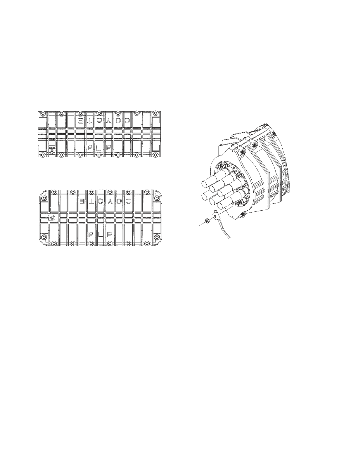
123
4
65
7
8
9
10 11 12
13 14
6.0" X 22" (15.24 CM X 55.88 CM)
15.04 Align the closing hardware and first HAND-
TIGHTEN in the torque sequence shown in
Figure 51. Once all closing hardware is hand-tight-
ened, repeat the torque sequence using a torque
wrench set at 55 inch pounds. After completing
torque sequence, re-torque the two outside corner
bolts on all four corners (in bold).
NOTE: SET TORQUE TO 55 INCH POUNDS.
FIGURE 51 - TORQUE SEQUENCE
15.05 Flash test and soap COYOTE Closure
according to accepted company practices, to
a maximum of 10 psi.
15.06 Release pressure from closure and replace
cap on air valve.
14
3
2
5
6
7
8
9
10
11
12
13
14
15
16
This manual suits for next models
3
Table of contents
Other PREFORMED LINE PRODUCTS Industrial Electrical manuals


Popular Industrial Electrical manuals by other brands

Murata
Murata GRM1885C1H331GA01 Series Reference sheet

Eaton
Eaton DILM7-21 Instruction leaflet

Murata
Murata GRT31CR61C335ME01 Series Reference sheet

Murata
Murata GCM1885C1H1R6BA16 Series Reference sheet

Murata
Murata GRM0335C1H9R7BA01 Series Reference sheet

Murata
Murata GRM0335C2A4R2CA01 Series Reference sheet


