2
Locate the drawing package that was shipped with your frame. This drawing package contains
important information specific to your frame. If your frame was delivered without a drawing package,
contact AGC or your local AGC distributor for a replacement package prior to installing the frame.
Frame Placement:
The Pro31-M frame should be located on a firm flat surface capable of supporting the press and
all of its contents when full. Ensure that adequate space is left around the frame for maintenance and plate
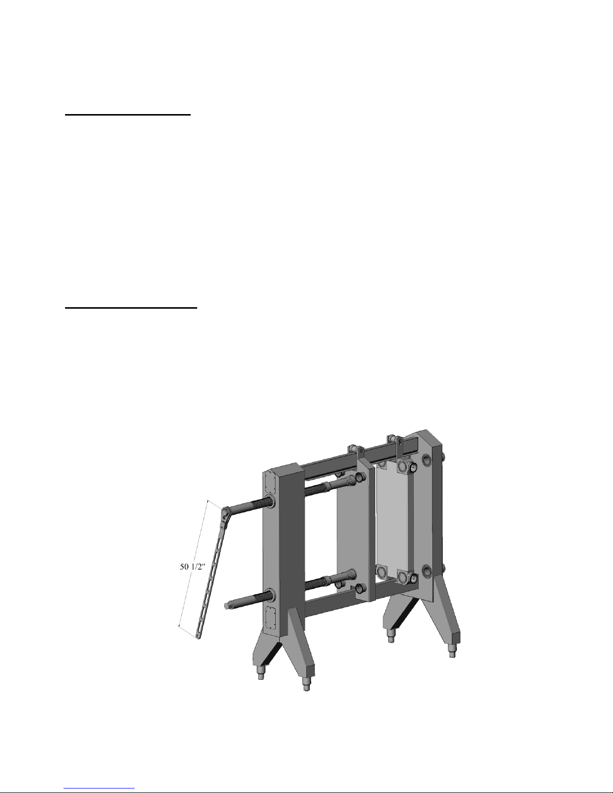
installation/removal. The drawing package will show the clearance required for the spindle shafts to be
fully retracted. This is the space required to fully open the press.
Each frame is equipped with adjustable ball feet to compensate for minor floor variations. To
adjust the ball foot height, turn the base of the foot clockwise to raise and counter clockwise to lower.
CAUTION: Never exceed the maximum port height dimension shown on the streaming diagram. If this
dimension is exceeded, the leg could disengage from the socket and the frame could tip.
When moving the frame, the top rail can provide a good lifting point. However, when using the
top rail as a lifting point, exercise caution to prevent damaging the plate hanger. Do not attempt to lift a
frame using the port nozzles as a lifting point. Lifting a frame by the port nozzles could crack the nozzles
causing leaks. Moving a frame that is fully populated with plates is not recommended.
Normal Operation:
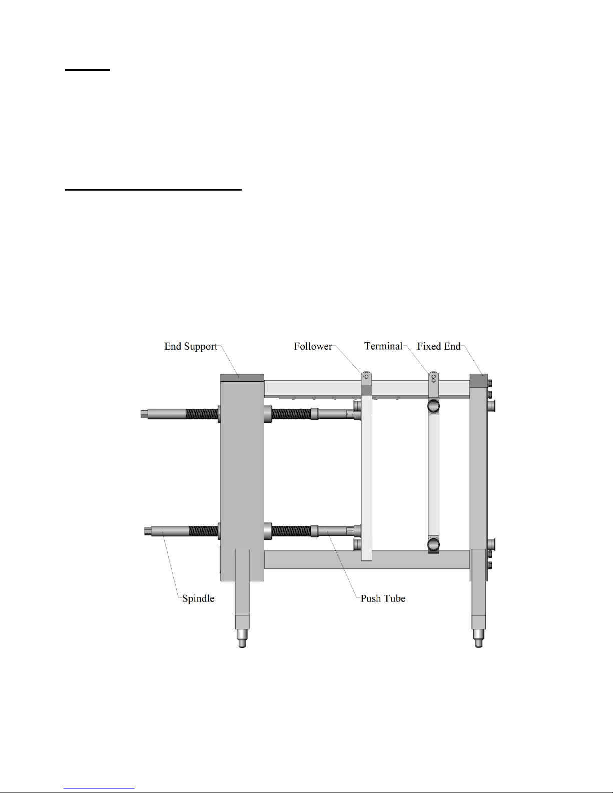
The Model Pro31-M Plate Heat Exchanger is a twin spindle manual closure press. The closing
force is developed by turning the two spindle screws on the end support (see figure 2). The spindle screws
have a hex machined on the end to accommodate the AGC Fatboy™ wrench. This wrench is sized
specifically to provide an efficient means for opening and closing of the Pro31-M press. As with all plate
heat exchangers, the unit must be cooled below 90º F and relieved of all internal pressure before opening.
Failure to follow this safety warning could result in serious injury to the operator or damage to the
heat exchanger.
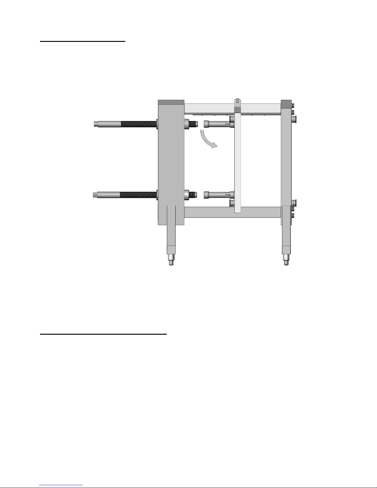
Figure 2
Open/Close with Fatboy Wrench