Preliminary TRACKER OFF ROAD LX6 User manual

REPAIR AND SERVICE MANUAL
699327-A
Issued August 2019
PRELIMINARY
For any questions about material in this manual, contact an authorized representative.
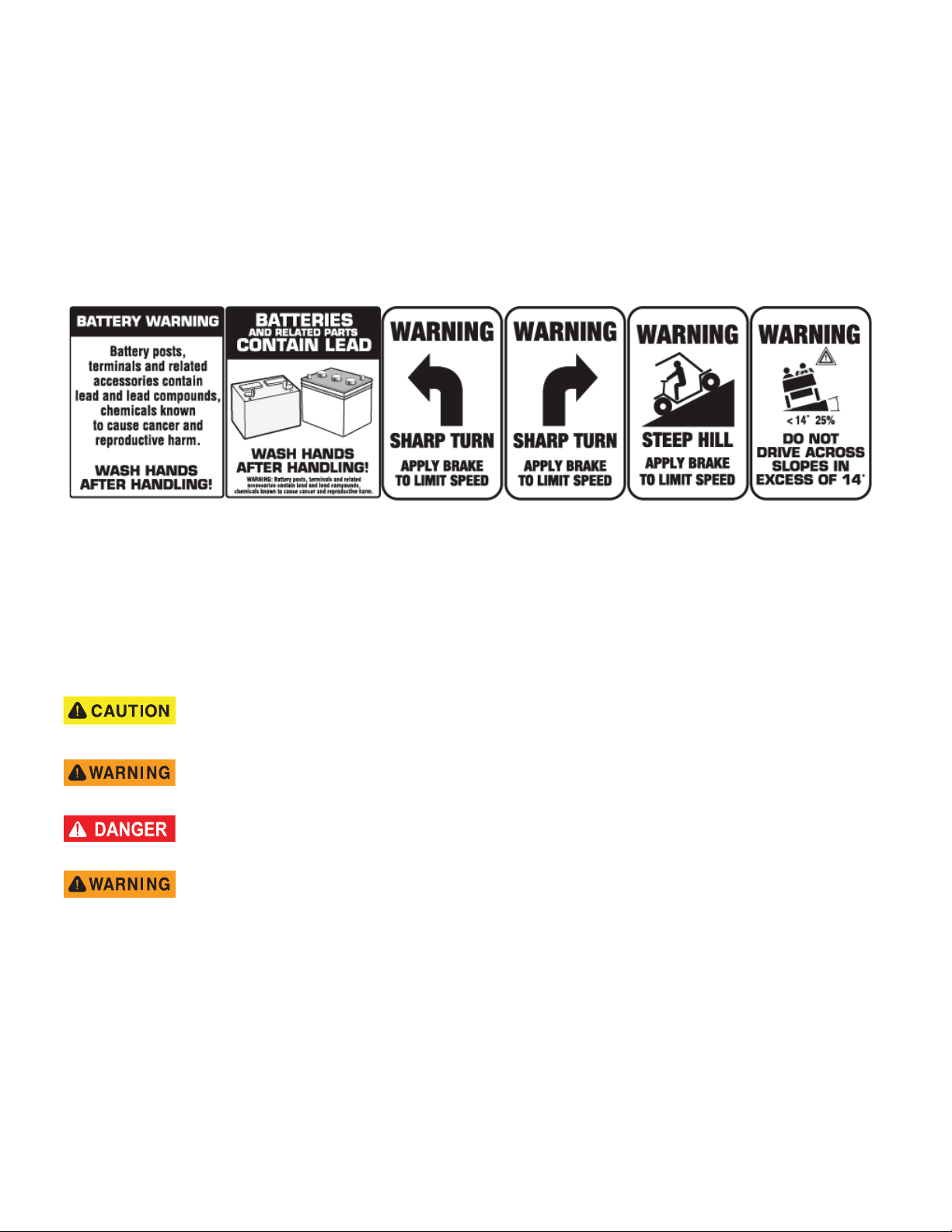
Read and understand all labels on the vehicle. Always replace any damaged or missing labels.
Steep hills allow the vehicles to move at faster speeds than speeds on a flat surface. To prevent the loss of vehicle control and possible
injury, speeds must be controlled to the maximum level ground speed indicated in the GENERAL SPECIFICATIONS section. Apply the
brake to control the speed.
If you operate the vehicle above the maximum specified speed, you can damage the drivetrain components. The damage caused by
speeds more than the maximum specified can cause a loss of vehicle control, is abuse, and will not be covered under the warranty.
Refer to the TRANSPORTING VEHICLE section to learn how to tow or move the vehicle from one location to another location.
If the vehicle is used in a commercial environment, signs must be in position to inform of possible conditions that can be dangerous.
Examples shown below.
NOTICES, CAUTIONS, WARNINGS AND DANGERS
Read the NOTICES, CAUTIONS, WARNINGS and DANGERS. The person who services a vehicle needs the mechanical
skill and experience to see possible hazardous conditions. Incorrect service or repairs can cause damage to the vehicle or
make the vehicle dangerous to operate.
NOTICE: A NOTICE indicates and describes information not related to personal injury.
A CAUTION indicates a dangerous condition that can cause injury that is not life threatening.
A WARNING indicates a dangerous condition that can cause death or serious injury.
A DANGER indicates a dangerous condition that will cause death or serious injury.
The battery posts, terminals and all related accessories contain lead and lead compounds.
Wash your hands after contacting any of these components.
PRELIMINARY

Never modify the vehicle in any way that will alter the weight distribution of the vehicle, decrease its stability or increase the speed
beyond the factory specifications. Such modifications can cause serious personal injury or death. The manufacturer prohibits and dis-
claims responsibility for any such modifications or any other alteration which would adversely affect the safety of the vehicle.
The manufacturer reserves the right to incorporate engineering and design changes to products in this manual, without obligation to
include these changes on units sold previously.
The information contained in this manual may be revised periodically by the manufacturer and therefore is subject to change without
notice.
THE MANUFACTURER DISCLAIMS LIABILITY FOR ERRORS IN THIS MANUAL, and SPECIFICALLY DISCLAIMS LIABILITY FOR INCIDEN-
TAL AND CONSEQUENTIAL DAMAGES resulting from the use of the information and materials in this manual.
These are the original instructions as defined by 2006/42/EC.
Dealer: 800-296-4804
Consumer: 877-394-6727
www.trackeroffroad.com
i
Repair and Service Manual
699327
REPAIR AND SERVICE MANUAL
TRACKER LX6, 72V
ELECTRIC POWERED UTILITY VEHICLE
MODEL YEAR 2020
PRELIMINARY

GENERAL INFORMATION
ii Repair and Service Manual 699327
This vehicle has been designed and assembled in the United States of America (USA). The Standards and Specifica-
tions listed in the following text originate in the USA unless otherwise indicated.
The use of non-Original Equipment Manufacturer (OEM) approved parts may void the warranty.
Tampering with or adjusting the governor to permit vehicle to operate at above factory specifications will void the vehi-
cle warranty.
When servicing the engine, all adjustments and replacement components must be per original vehicle specifications in
order to maintain the United States of America Federal and State emission certification applicable at the time of manu-
facture.
BATTERY PROLONGED STORAGE
Batteries self-discharge over time. The rate of self-discharge varies depending on the ambient temperature, the age
and condition of the battery.
A fully charged battery will not freeze unless the temperature falls below -75°F (- 60°C).
For winter storage, the battery must be clean, fully charged and disconnected from any source of electrical drain.
BATTERY DISPOSAL
Lead-acid batteries are recyclable. Return whole scrap batteries to distributor, manufacturer or lead smelter for recy-
cling. For neutralized spills, place residue in acid-resistant containers with absorbent material, sand or earth and dis-
pose of in accordance with local, state and federal regulations for acid and lead compounds. Contact local and/or state
environmental officials regarding disposal information.
PRELIMINARY

B
TABLE OF CONTENTS
iii
Repair and Service Manual
699327
SAFETY INFORMATION
GENERAL ........................................................................................................................ XI
GENERAL OPERATION.................................................................................................. XI
MAINTENANCE .............................................................................................................. XII
VENTILATION................................................................................................................. XII
GENERAL INFORMATION AND ROUTINE MAINTENANCE
SERIAL NUMBER LABEL LOCATION ............................................................................. 1
TRANSPORTING VEHICLE ............................................................................................. 2
Towing .................................................................................................................. 2
Hauling ................................................................................................................. 2
SERVICING THE ELECTRIC VEHICLE ........................................................................... 2
ROUTINE MAINTENANCE............................................................................................... 2
REAR AXLE ...................................................................................................................... 3
BRAKES............................................................................................................................ 3
TIRES................................................................................................................................ 3
LIGHT BULB REPLACEMENT ......................................................................................... 3
VEHICLE CLEANING AND CARE.................................................................................... 3
VEHICLE CARE PRODUCTS........................................................................................... 3
SUN TOP AND WINDSHIELD .......................................................................................... 3
SERVICE SCHEDULE...................................................................................................... 4
HARDWARE ..................................................................................................................... 5
SAFETY
NOTICES, CAUTIONS, WARNINGS AND DANGERS .................................................... 7
IMPORTANT SAFETY WARNING.................................................................................... 7
MODIFICATIONS TO VEHICLE ....................................................................................... 7
GENERAL MAINTENANCE.............................................................................................. 7
BEFORE SERVICING THE VEHICLE .............................................................................. 7
ADDITIONAL WARNINGS................................................................................................ 8
BATTERY REMOVAL & INSTALLATION ......................................................................... 8
LIFTING THE VEHICLE.................................................................................................... 9
Entire Vehicle ....................................................................................................... 9
Front of Vehicle .................................................................................................. 10
Rear of Vehicle ................................................................................................... 10
PRELIMINARY

B
iv Repair and Service Manual
TABLE OF CONTENTS
699327
WHEELS AND TIRES
WHEEL AND TIRE SERVICE.......................................................................................... 13
Wheel Installation ................................................................................................13
BODY
GENERAL........................................................................................................................ 17
BODY COMPONENT REPLACEMENT .......................................................................... 17
Rocker Panel ......................................................................................................18
Fender Flare .......................................................................................................19
Cowl ....................................................................................................................20
Control Panel ......................................................................................................21
Instrument Panel .................................................................................................22
Front Fascia and Mounting Bracket ....................................................................23
Seat Back ............................................................................................................23
Front Seat and Seat Frame ................................................................................24
Flip Seat, Seat Back Support, and Footrest ........................................................26
Truck Bed and Bed Support ................................................................................28
Rear Body ...........................................................................................................30
PAINTING ........................................................................................................................ 32
Minor Scratches ..................................................................................................32
Larger Scratches .................................................................................................32
Complete Panel Repair .......................................................................................32
FRONT SUSPENSION, STEERING, & AXLE
MAINTENANCE............................................................................................................... 35
Lubrication ..........................................................................................................35
Wheel Bearing and King Pin Bushing inspection ................................................35
Wheel Bearing Packing .......................................................................................35
Wheel Bearing Adjustment .................................................................................36
Wheel Alignment .................................................................................................36
FRONT SUSPENSION .................................................................................................... 37
Front Shock Absorber Replacement ...................................................................37
Front Spring Replacement ..................................................................................38
Hub Replacement ...............................................................................................40
Wheel Bearing and Race Replacement ..............................................................40
PRELIMINARY

B
TABLE OF CONTENTS
v
Repair and Service Manual
699327
STEERING...................................................................................................................... 42
Rack Ball Joint Replacement ............................................................................. 43
Tie Rod End Inspection/Replacement ................................................................ 43
Bellows Replacement ......................................................................................... 44
Rack and Pinion Unit Replacement ................................................................... 45
Pinion Seal Replacement ................................................................................... 45
Spindle Replacement ......................................................................................... 46
Front Axle Replacement ..................................................................................... 47
Rack and Pinion Unit Disassembly and Inspection ............................................ 47
Checking/Adjusting Rack Extension-to-Rack and Pinion Unit Clearance .......... 48
Steering Wheel Replacement ............................................................................ 49
Steering Shaft and Column Replacement .......................................................... 50
BATTERIES AND BATTERY CHARGER
SAFETY .......................................................................................................................... 53
BATTERY........................................................................................................................ 53
Batteries Removal .............................................................................................. 54
Battery Installation .............................................................................................. 55
BATTERY MAINTENANCE ............................................................................................ 56
At Each Charging Cycle ..................................................................................... 56
Monthly ............................................................................................................... 56
Temperature Affects Battery Capacity ............................................................... 56
Electrolyte Level and Water ............................................................................... 56
Cleaning Batteries .............................................................................................. 57
Prolonged Storage ............................................................................................. 58
Battery Charging ................................................................................................ 58
AC Voltage ......................................................................................................... 59
FAULT TESTING ............................................................................................................ 59
Hydrometer ........................................................................................................ 59
Using Hydrometer .............................................................................................. 60
BATTERY CHARGER..................................................................................................... 61
Charger Description ........................................................................................... 61
Portable Charger Installation .............................................................................. 61
PRELIMINARY

B
vi Repair and Service Manual
TABLE OF CONTENTS
699327
ELECTRONIC SPEED CONTROL
PERFORMANCE ............................................................................................................. 63
Speed Control .....................................................................................................63
Pedal-Up Braking ................................................................................................63
Walk-Away Feature .............................................................................................63
Anti-Roll Back Feature ........................................................................................63
Anti-Stall Feature ................................................................................................63
High Pedal Disable Feature ................................................................................63
Diagnostic Mode Feature ....................................................................................63
OPERATION.................................................................................................................... 64
Pedal Box ............................................................................................................64
Speed Sensor .....................................................................................................65
Controller ............................................................................................................65
GENERAL FAULT TESTING........................................................................................... 65
Testing ................................................................................................................65
INDUCTIVE THROTTLE SENSOR (ITS) TESTING AND REPLACEMENT ................... 66
MOTOR
GENERAL........................................................................................................................ 69
Motor Removal ....................................................................................................69
Motor Installation .................................................................................................70
MOTOR TESTS ............................................................................................................... 70
ELECTRICAL SYSTEM
VOLTAGE TESTING FOR BATTERIES.......................................................................... 77
MAIN HARNESS.............................................................................................................. 77
Power Supply ......................................................................................................77
Accessory Wiring ................................................................................................78
Faulty Wire Replacement ....................................................................................78
Tail Light and Bulb ..............................................................................................78
Halogen Headlight Bulb ......................................................................................79
LED Bulb .............................................................................................................79
Headlight Assembly ............................................................................................79
Controller Replacement ......................................................................................80
Solenoid Replacement ........................................................................................81
DC to DC Converter ............................................................................................82
Reverse Buzzer ..................................................................................................82
PRELIMINARY

B
TABLE OF CONTENTS
vii
Repair and Service Manual
699327
Horn ................................................................................................................... 83
FAULT TESTING ............................................................................................................ 83
General .............................................................................................................. 83
Testing Battery Voltage ...................................................................................... 83
Continuity Check ................................................................................................ 84
Testing A Switch for Continuity .......................................................................... 84
Testing A Solenoid for Continuity ....................................................................... 84
ACCESORIES................................................................................................................. 85
Keyswitch ........................................................................................................... 85
Hour Meter ......................................................................................................... 86
Rocker Switches ................................................................................................ 86
USB Port ............................................................................................................ 86
MECHANICAL BRAKES
BRAKE SYSTEM OVERVIEW........................................................................................ 90
General Description ........................................................................................... 90
How the Service Brake Works ........................................................................... 90
Equalizer Link ..................................................................................................... 90
Automatic Adjuster Mechanism .......................................................................... 90
How the Parking Brake Works ........................................................................... 91
Compensator Assembly ..................................................................................... 91
Kick-Off Actuating Linkage ................................................................................. 91
FAULT TESTING TABLE................................................................................................ 92
FAULT TESTING AND INSPECTION............................................................................. 94
New Vehicles ..................................................................................................... 94
Fault Testing and Inspection Procedures ........................................................... 94
Brake Pedal and Linkage Inspection .................................................................. 94
Periodic Brake Performance Test (PBPT) ......................................................... 97
Aggressive Stop Test ......................................................................................... 98
Wheel Brake Inspection ..................................................................................... 98
MAINTENANCE AND REPAIRS................................................................................... 101
Parts Replacement vs. Repair ......................................................................... 101
Adjusting Brake Pedal Free Travel .................................................................. 101
Parking Brake Latching Force .......................................................................... 102
Brake Drum Removal and Installation .............................................................. 102
Wheel Brake Service ........................................................................................ 103
PRELIMINARY

B
viii Repair and Service Manual
TABLE OF CONTENTS
699327
Backing Plate/Entire Wheel Brake Assembly Removal and Installation ...........104
Brake Shoe and Adjuster Replacement ............................................................104
Brake Cable and Equalizer Assembly Removal and Installation ......................105
Compensator Assembly, Removal and Installation ..........................................106
Brake Pedal Removal and Installation ..............................................................107
Kick Off Cam Adjustment ..................................................................................107
Parking Brake Catch Bracket Removal and Installation ...................................108
Parking Brake Pedal Removal and Installation .................................................108
Pedal Bumper Adjustment ................................................................................108
Parking Brake Release Linkage and Kick-Off Cam Removal and Replacement 109
REAR AXLE
REAR AXLE MAINTENANCE........................................................................................ 111
Replacing the Lubricant ....................................................................................111
Fill Procedure ....................................................................................................112
REAR AXLE REMOVAL ................................................................................................ 112
REAR AXLE DISASSEMBLY ........................................................................................ 112
Axle Shaft, Bearing and Seal Removal .............................................................112
REAR SUSPENSION
GENERAL...................................................................................................................... 115
SHOCK ABSORBER ..................................................................................................... 115
Removal ............................................................................................................115
Installation .........................................................................................................115
REAR LEAF SPRINGS.................................................................................................. 116
Removal ............................................................................................................116
Installation .........................................................................................................116
REAR AXLE................................................................................................................... 117
Removal ............................................................................................................117
Installation .........................................................................................................118
WEATHER PROTECTION
GENERAL...................................................................................................................... 121
Trailering ...........................................................................................................121
SUN TOP ....................................................................................................................... 121
SPILT WINDSHIELD ..................................................................................................... 123
FULL WINDSHIELD....................................................................................................... 124
PRELIMINARY

B
TABLE OF CONTENTS
ix
Repair and Service Manual
699327
FAULT TESTING
SUSPENSION AND STEERING................................................................................... 127
CURTIS CONTROLLER ............................................................................................... 128
General ............................................................................................................ 128
Navigation ........................................................................................................ 128
Changing Data Value ....................................................................................... 128
Favorites .......................................................................................................... 128
Main Menu Definitions ...................................................................................... 129
LED Fault Code Chart ...................................................................................... 133
Curtis Handheld Diagnostic Tool Function ....................................................... 142
COMPONENT TESTING .............................................................................................. 148
Voltmeter .......................................................................................................... 148
Fuses - Testing ................................................................................................ 148
Key Switch - Testing ........................................................................................ 149
State of Charge (SOC) / Hour Meter - Testing ................................................. 149
Electronic Speed Controller Solenoid - Testing ............................................... 149
Temperature Sensor - Testing ......................................................................... 150
Electronic Speed Sensor - Testing ................................................................... 151
AC Motor Bench Test ....................................................................................... 151
GENERAL SPECIFICATIONS
VEHICLE SPECIFICATIONS........................................................................................ 155
APPENDIX A
BATTERY CHARGER USER’S GUIDE ........................................................................ 157
PRELIMINARY

xRepair and Service Manual
TABLE OF CONTENTS
Notes:
699327
PRELIMINARY

SAFETY INFORMATION
Read all of SAFETY and this section before attempting any procedure. Pay particular attention to Notices, Cautions, Warnings and Dangers.
iii
Repair and Service Manual
699327
SAFETY INFORMATION
This manual contains recommended maintenance procedures from the manufacturer. Follow the procedures and fault
isolation information to get the best service from the product. To decrease the risk of personal injury or property damage,
read and follow all safety information and operational procedures in this manual.
GENERAL
Vehicles are used for different purposes, so it is not possible to know and inform of every possible occurrence. Be careful
when you drive to prevent avoidable personal injury or damage to the vehicle. All users must read and obey this manual.
Make sure to give special attention to the CAUTIONS, WARNINGS and DANGERS.
Anyone who operates the vehicle must read the entire owner’s guide provided with the purchase of the vehicle, paying
particular attention to the CAUTIONS, WARNINGS and DANGERS within.
For questions about this vehicle, contact your dealer.
The manufacturer has the right to change the design of the vehicle. There is no responsibility to make the changes on
units purchased before design changes were made. The information in this manual can change without notice.
THE MANUFACTURER IS NOT LIABLE FOR ERRORS IN THIS MANUAL OR INCIDENTAL OR CONSEQUENTIAL
DAMAGES THAT RESULT FROM THE USE OF THE MATERIAL IN THIS MANUAL.
This vehicle meets the current applicable standard for safety and performance requirements.
These vehicles are for off-road use. They DO NOT meet the federal Motor Vehicle Safety Standards of the United States
of America (USA) and are not for operation on the public streets.
Refer to the General Specifications section for capacity of the vehicle (See GENERAL SPECIFICATIONS on page 155).
Ensure all electrical accessories are grounded directly to the negative (-) battery post. Never use the chassis or body
as a ground connection.
Do not change the vehicle in any manner that changes the weight distribution, decreases
stability, increases speed, or extends the necessary distance to stop more than the factory
specification. Such changes can cause personal injury or death.
Do not change the vehicle in any manner that changes the weight distribution, decreases stability, increases speed or
extends the necessary distance to stop more than the factory specification. The manufacturer is not responsible for
changes that cause the vehicle to be dangerous.
Do not allow anyone below the height of 59 inches (150 cm) to operate the vehicle.
Speed should be moderated by the environmental conditions, terrain, and common sense.
GENERAL OPERATION
ALWAYS:
• Use the vehicle responsibly and keep the vehicle in safe condition for operation.
• Read and obey all warnings and operation instruction labels on the vehicle.
• Follow all safety rules in the area where the vehicle is operated.
• When there is a risk of lightning, leave the vehicle and look for a safe location to wait until the lightning has stopped.
• Drive the vehicle only as fast as terrain and conditions allow.
• Apply the brake to control the speed on steep grades.
• Keep enough distance between vehicles.
• Decrease speed in wet areas.
• Be careful when you make sharp turns, or turns you are not familiar with.
• Be careful when you drive on loose terrain.
• Be careful when you operate the vehicle in a populated area.
PRELIMINARY

iv Repair and Service Manual
SAFETY INFORMATION
699327
MAINTENANCE
ALWAYS:
• Replace damaged or missing warning, caution or information labels.
• Service the vehicle according to the periodic service schedule in this manual.
• Make sure that approved and qualified personnel do all repairs.
• Follow the manufacturer’s maintenance procedures.
• Use insulated tools within the battery area to prevent sparks or battery explosion.
• Use specified replacement parts. DO NOT use replacement parts of less quality.
• Use recommended tools.
• Make sure that tools and procedures not specified by the manufacturer will not be a safety risk to personnel or oper-
ation of the vehicle.
• Support the vehicle with wheel chocks and jack stands. NEVER get under a vehicle that is supported by a jack
alone. Lift the vehicle according to the manufacturers instructions.
• Make sure you service the vehicle in an area away from open flame or sparks.
• Know that a vehicle in need of repair does not operate correctly and can be dangerous to operate.
• After making repairs or performing maintenance, test the vehicle in a safe area that is free from vehicle and person
traffic.
• Make sure to record and keep all of the maintenance history of the vehicle.
VENTILATION
ALWAYS:
• Charge the vehicle in a well-ventilated area.
• Charge in an area free from flammable liquids and items.
• Charge the vehicle in an area that is free from flame or spark. Charge in an area that is a safe distance from gas
water heaters and furnaces.
• Use a dedicated circuit for the battery charger. Do not plug other appliances into the receptacle when the charger is
in operation.
• Operate the charger according to the charger manufacturers recommendations or applicable electrical code.
PRELIMINARY
GENERAL INFORMATION AND ROUTINE MAINTENANCE
Read all of SAFETY and this section before attempting any procedure. Pay particular attention to Notices, Cautions, Warnings and Dangers.
1
Repair and Service Manual
699327
GENERAL INFORMATION AND ROUTINE MAINTENANCE
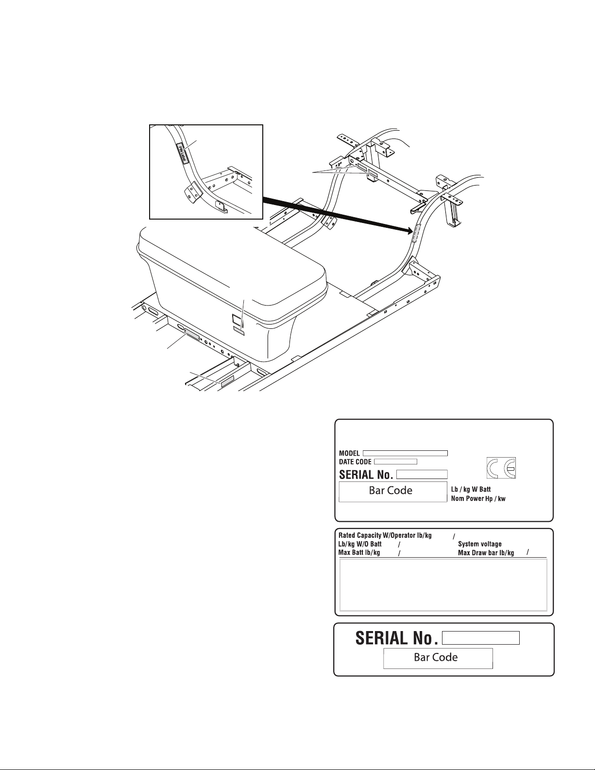
SERIAL NUMBER LABEL LOCATION
Fig. 1 Serial Number & PIN Label Locations
Serial number labels (with manufacture date code) and
PIN plates are located in several locations. Part “A” and
part “B” are located on the cross-member that spans the
frame at the rear wheels. Part “C” is located under the
charger receptacle. Part “D” is located on the frame rail
below the driver’s seat floorboard. The PIN plates are
located on the inside of the frame rail at the driver’s side
rear wheel and on the frame cross-member below the
front floorboard.(Ref Fig. 2) (Ref Fig. 1)
Design changes take place on an ongoing basis. In order
to obtain correct components for the vehicle, the manu-
facture date code, serial number and vehicle model must
be provided when ordering service parts.
Fig. 2 Serial Number Labels
PIN Plate
PART“D”
PAR T “C ”
PAR T “A” PART“B”
PIN Label
PIN Label
SN Label
Part “A” & “B”
SN Label
Part “D”
PIN Plate
SN Label
Part “C”
Label No.
V
PART A
PART BPART C/D
PRELIMINARY
B
2Repair and Service Manual
GENERAL INFORMATION AND ROUTINE MAINTENANCE
Read all of SAFETY and this section before attempting any procedure. Pay particular attention to Notices, Cautions, Warnings and Dangers.
699327
TRANSPORTING VEHICLE
Towing
This vehicle is not designed to be
towed.
It is recommended that the vehicle be moved by placing
the entire vehicle on a trailer, flatbed truck or other
suitable transport.
Hauling
To reduce the possibility of severe
injury or death while transporting
vehicle:
Secure the vehicle and contents.
Never ride on vehicle being transported.
Always remove windshield before
transporting.
Maximum speed with sun top installed is 50
mph (80 kph).
If the vehicle is to be transported at highway speeds, the
sun top must be removed and the seat bottom secured
(See SUN TOP on page 121). When transporting vehicle
below highway speeds, check for tightness of hardware
and cracks in sun top at mounting points. Always remove
windshield when transporting (See SPILT WINDSHIELD
on page 123). Always check that the vehicle and contents
are adequately secured before transporting. The rated
capacity of the trailer or truck must exceed the weight of
the vehicle and load plus 1000 lbs. (454 kg) (See GEN-
ERAL SPECIFICATIONS on page 155). Lock the park
brake and secure the vehicle using ratchet tie downs.
SERVICING THE ELECTRIC VEHICLE
To prevent severe injury or death,
resulting from improper servicing
techniques, observe the following
Warnings:
Do not attempt any type of servicing
operations before reading and
understanding all notes, cautions and
warnings in this manual.
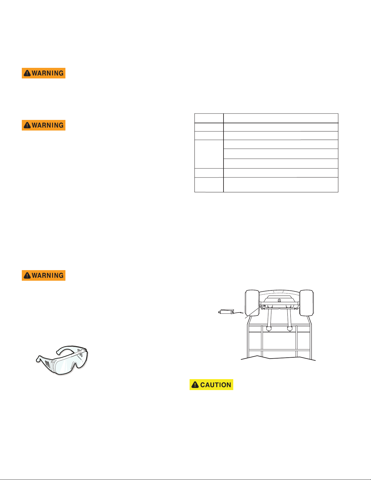
Any servicing requiring adjustments to be
made to the powertrain while the motor is
running must be made with both drive
wheels raised.
Wear eye protection
when working on the
vehicle. In particular,
use care when working
around batteries, or
using solvents or
compressed air.
To reduce the possibility of causing an
electrical arc, which could result in a battery
explosion, turn off all electrical loads from
the batteries before removing any heavy
gauge battery wires.
To prevent the possibility of motor
disintegration, never operate vehicle at full
throttle for more than 4 - 5 seconds while
vehicle is in a “no load” condition.
It is in the best interest of both vehicle owner and servic-
ing dealer to carefully follow the procedures recom-
mended in this manual. Adequate preventive
maintenance, applied at regular intervals, is the best
guarantee for keeping the vehicle both dependable and
economical.
Before a new vehicle is put into operation, it is recom-
mended that the items shown in the INITIAL SERVICE
CHART be performed (Ref Fig. 3).
Vehicle batteries must be fully charged before initial use.
Fig. 3 Initial Service Chart
ROUTINE MAINTENANCE
NOTICE: Some maintenance items must be serviced
more frequently on vehicles used under severe driv-
ing conditions.
This vehicle will give years of satisfactory service
provided it receives regular maintenance. Refer to the
Periodic Service Schedule for appropriate service inter-
vals (Ref Fig. 5). Refer to Lubrication Point for
appropriate lubrication location (Ref Fig. 4).
Fig. 4 Lubrication Points
Do not use more than three pumps
of grease for each grease fitting at
any one time- Excess grease may
cause grease seals to fail or grease migration into
areas that could damage components.
Putting more than three pumps of grease in a grease fit-
ting could damage grease seals and cause premature
bearing failure.
ITEM SERVICE OPERATION
Batteries Charge batteries
Seats Remove protective plastic covering
Brakes Check operation and adjust if necessary
Establish acceptable stopping distance
Check hydraulic brake fluid level
Tires Check air pressure (see SPECIFICATIONS)
Portable Remove from vehicle and properly mount
Charger
Rack
Ball
Joint
PRELIMINARY

B
GENERAL INFORMATION AND ROUTINE MAINTENANCE
Read all of SAFETY and this section before attempting any procedure. Pay particular attention to Notices, Cautions, Warnings and Dangers.
3
Repair and Service Manual
699327
REAR AXLE
The only maintenance required for the first five years is
the periodic inspection of the lubricant level. The rear axle
is provided with a lubricant level check/fill plug located on
the bottom of the differential. Unless leakage is evident,
the lubricant need to be only replaced after five years
(See Replacing the Lubricant on page 111).
BRAKES
After the vehicle has been put into service, it is recom-
mended that the brakes be checked daily by performing a
brake test (See Periodic Brake Performance Test (PBPT)
on page 97).
To prevent severe injury or death
resulting from operating a vehicle
with improperly operating brake
system, the braking system must be properly
maintained. All driving brake tests must be done in
a safe location with regard for the safety of all
personnel.
TIRES
Tire condition should be inspected periodically (See SER-
VICE SCHEDULE on page 4). Inflation pressures should
be checked when the tires are cool. Be sure to reinstall
valve dust cap after checking or inflating (See WHEEL
AND TIRE SERVICE on page 13).
LIGHT BULB REPLACEMENT
Refer to ELECTRICAL SYSTEM for information regard-
ing light bulb replacement (See Halogen Headlight Bulb
on page 79).
VEHICLE CLEANING AND CARE
When pressure washing vehicle, do
not use pressure in excess of 700
psi (4826 kPa). To prevent cosmetic
damage, do not use any abrasive or reactive
solvents to clean plastic parts.
It is important that proper techniques and cleaning materi-
als be used. Using excessive water pressure may cause
damage to seals, plastics, the electrical system, body fin-
ish or seat material. Do not use pressure in excess of 700
psi (4826 kPa) to wash vehicle.
Normal cleaning of vinyl seats and plastic or rubber trim
require the use of a mild soap solution applied with a
sponge or soft brush and wipe with a damp cloth.
Removal of oil, tar, asphalt, shoe polish, etc. will require
the use of a commercially available vinyl/rubber cleaner.
The painted surfaces of the vehicle provide attractive
appearance and durable protection. Frequent washing
with lukewarm or cold water is the best method of pre-
serving the painted surfaces.
Do not use hot water, strong soap or harsh chemical
detergents.
Rubber parts should be cleaned with non-abrasive
household cleaner.
Occasional cleaning and waxing with non-abrasive
products designed for ‘clear coat’ automotive finishes will
enhance the appearance and durability of the painted
surfaces.
Corrosive materials used as fertilizers or for dust control
can collect on the underbody of the vehicle. These mate-
rials will accelerate corrosion of underbody parts. It is rec-
ommended that the underbody be flushed occasionally
with plain water. Thoroughly clean any areas where mud
or other debris can collect. Sediment packed in closed
areas should be loosened to ease its removal, taking care
not to chip or otherwise damage paint.
VEHICLE CARE PRODUCTS
To help maintain the vehicle, there are several products
available through local Distributors, authorized Branches,
or the Service Parts Department.
• Touch-up paint specially formulated to match vehi-
cle colors for use on TPE (plastic) bodies (P/N
28140-G** and 28432G**).
• Multi-purpose Battery Protectant formulated to form
a long-term, flexible, non-tacky, dry coating that
will not crack, peel, or flake over a wide tempera-
ture range (P/N 606312).
• Multi-purpose Hand Cleaner is an industrial
strength cleaner containing no harsh solvents, yet
gently lifts grease off hands. May be used with or
without water (P/N 607636).
• Battery Maintenance Kit for complete battery clean-
ing and watering, with battery maintenance
instructions (P/N 25587G01).
• Plexus plastic cleaner and polish removes minor
scratches from windshield (P/N 606314).
SUN TOP AND WINDSHIELD
The sun top does not provide
protection from roll over or falling
objects.
The windshield does not provide Complete
protection from tree limbs or flying objects.
The sun top and windshield are designed for weather pro-
tection only.
Clean with lots of water and a clean cloth. Minor
scratches may be removed using a commercial plastic
polish or Plexus plastic cleaner available from Service
Parts Department.
PRELIMINARY

B
4Repair and Service Manual
GENERAL INFORMATION AND ROUTINE MAINTENANCE
Read all of SAFETY and this section before attempting any procedure. Pay particular attention to Notices, Cautions, Warnings and Dangers.
699327
SERVICE SCHEDULE
C- CHECK C&A - CHECK & ADJUST CL - CLEAN R- REPLACE
Fig. 5 Periodic Service Schedule
REMARKS
Before each use DAILY
DAILY
WEEKLY
20 hrs
MONTHLY
50 hrs
QUARTERLY
125 hrs
SEMI-ANNUAL
250 - 300 hrs
ANNUAL
5 YEARS
Tires - Check pressure and inspect condition of tires & rims. C C C C C C
Hardware - Check for loose or missing. C C C C C C
Reverse Warning Indicator C C C C C C
Overall Vehicle Condition C C C C C C
Battery Pack - Check state of charge, condition, loose terminals, corrosion,
hold down & hardware.
C C CL CL CL CL
Brake Pedal - Check for smooth operation C C C C C C
Parking Brake - Check for correct hold capability. C C C&A C&A C&A C&A
Accelerator - Check for smooth operation. C C C C C C
Charger / Receptacle - Inspect charger connector and receptacle. C C C C C C
Brakes - Conduct brake performance test; adjust if required. C&A C&A C&A C&A
Wiring - Inspect for loose connections, broken or missing insulation. C C C C
Direction Selector - Inspect attachment and mechanism. C&A C&A C&A C&A
Steering Assembly - Check for excess play, loose or missing hardware. C C C C
Tie Rods - Check for excess play, bent rods, loose or missing hardware. C C C C
Front Axle - Check for damage to axle, loose or missing hardware. C C C
Rear Axle - Check fluid level, oil leakage, noise, loose or missing hardware. C C C C
Parking Brake - Inspect linkage rods, latch arm and catch bracket. C C C
Parking Brake - Lubricate with light oil. Do not lubricate cables or brake latch. C&A C&A C&A
Rear Axle - Drain & replace fluid. R
Rear Suspension - Inspect for shock oil leakage, worn bushings, loose or
missing hardware.
CCC
Front Suspension - Inspect for strut oil leakage, excessive play in hubs or
kingpins, worn bushings, loose or missing hardware.
CCC
Front Wheel Alignment - Inspect for unusual tire wear. C&A C&A C&A
Steering Assembly - Inspect bellows and pinion seal for damage and leakage. C C
Rack End Ball Joint - Check for noise and loose or missing hardware. C C
NOTE: Some maintenance items must be serviced more frequently on vehicles used under severe driving conditions.
PRELIMINARY

B
GENERAL INFORMATION AND ROUTINE MAINTENANCE
Read all of SAFETY and this section before attempting any procedure. Pay particular attention to Notices, Cautions, Warnings and Dangers.
5
Repair and Service Manual
699327
HARDWARE
Periodically the vehicle should be inspected for loose fas-
teners. Fasteners should be tightened in accordance with
the Torque Specifications table (Ref Fig. 6).
Use care when tightening fasteners and refer to the Tech-
nician’s Repair and Service Manual for specific torque
values.
Generally, two grades of hardware are used in the
vehicle.
• Grade 5 hardware can be identified by the three
marks on the hexagonal head.
• Unmarked hardware is Grade 2 .
Fig. 6 Torque Specifications
ALL TORQUE FIGURES ARE IN FT. LBS. (Nm)
BOLT SIZE
Grade 2
1/4" 5/16" 3/8" 7/16" 1/2" 9/16" 5/8" 3/4" 7/8" 1"
Unless otherwise noted in text, tighten all hardware in accordance with this chart.
This chart specifies 'lubricated' torque figures. Fasteners that are plated or lubricated when
installed are considered 'wet' and require approximately 80% of the torque required for 'dry' fasteners.
4
(5)
8
(11)
15
(20)
24
(33)
35
(47)
55
(75)
75
(102)
130
(176)
125
(169)
190
(258)
Grade 5
Grade 8
6
(8)
13
(18)
23
(31)
35
(47)
55
(75)
80
(108)
110
(149)
200
(271)
320
(434)
480
(651)
6
(8)
18
(24)
35
(47)
55
(75)
80
(108)
110
(149)
170
(230)
280
(380)
460
(624)
680
(922)
BOLT SIZE
Class 5.8
(Grade 2)
M4 M5 M6 M8 M10 M12 M14
1
(2)
2
(3)
4
(6)
10
(14)
20
(27)
35
(47)
55
(76.4)
Class 8.8
(Grade 5)
2
(3)
4
(6)
7
(10)
18
(24)
35
(47)
61
(83)
97
(131)
Class 10.9
(Grade 8)
3
(4)
6
(8)
10
(14)
25
(34)
49
(66)
86
(117)
136
(184)
5.8
8.8
10.9
PRELIMINARY

6Repair and Service Manual
GENERAL INFORMATION AND ROUTINE MAINTENANCE
Read all of SAFETY and this section before attempting any procedure. Pay particular attention to Notices, Cautions, Warnings and Dangers.
Notes:
699327
PRELIMINARY
Table of contents
Popular Utility Vehicle manuals by other brands


Carry-On Trailer Corporation
Carry-On Trailer Corporation 7x16CG User's manual - safety guide

BERG
BERG Extra Sport Theme user manual

Toro
Toro 7359 Operator's manual

Cub Cadet
Cub Cadet 550 2018 Operator's manual

Toro
Toro Workman 07143 installation instructions

Polaris
Polaris RANGER XP 900 2013 owner's manual