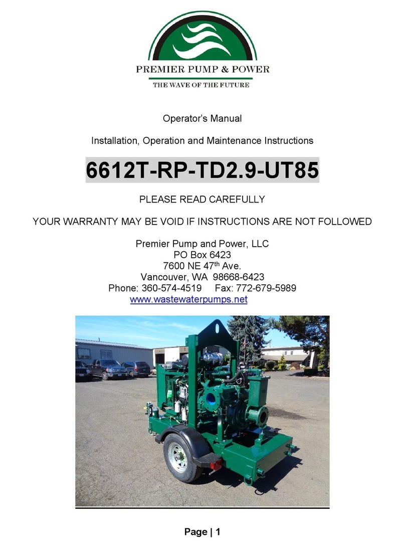
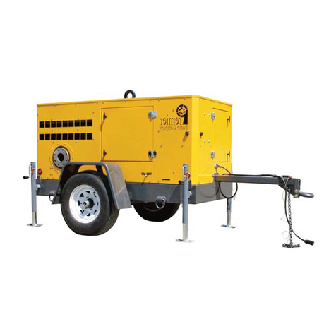
Premier pump & power 4NNT-RP-D2.9L-T85 User manual

Operator’s Manual
Installation, Operation and Maintenance Instructions
4NNT-RP-D2.9L-T85
PLEASE READ CAREFULLY
YOUR WARRANTY MAY BE VOID IF INSTRUCTIONS ARE NOT FOLLOWED
Premier Pump and Power, LLC
PO Box 6423
7600 NE 47th Ave.
Vancouver, WA 98668-6423
Phone: 360-574-4519 Fax: 772-679-5989
www.wastewaterpumps.net

Page 2 of 26
CONTENTS
Page Number
Overview of Pump Design............................................................................ 4
Operation of the Pump ................................................................................. 9
Pre-start Checklist.......................................................................................10
Starting the Engine......................................................................................10
Normal Operating Parameters ....................................................................10
Starting the Engine Using the AutoStart Controller .....................................11
Maintenance Safety Instructions .................................................................12
Replacement Parts......................................................................................13
General Maintenance Guidelines ................................................................14
Troubleshooting the Engine ........................................................................15
Troubleshooting the Pump ..........................................................................18
Troubleshooting the Priming System...........................................................19
Eliminating Pump Problems ........................................................................20
Pump Performance Curve...........................................................................23
Warranty......................................................................................................24

Page 3 of 26
Questions regarding this machinery should
be directed toward the manufacturer.
Serial numbers of the engine or pump and
the Mfg. Serial # are required to source the
correct replacement components.
This and other useful information are found
on the Vintag, affixed to the non-curb side
of the trailer near the tongue.

Page 4 of 26
OVERVIEW OF PUMP DESIGN
The Premier Pump 4NNT-RP-D2.9L-T85 series is an automatic self-priming pump driven
by a diesel engine.Specifically designed to handle abrasive fluids such as sewage and
sludge containing solids, it provides a dependable, high efficiency solution for your
pumping requirements. The pump has proven itself fully capable in a variety of
applications including those with intermittent flow conditions, and both open and sewage
by-pass applications where a moderate amount of air handling is required.
CHASSIS
The chassis has been structurally engineered to support the complete pumping unit along
with a tank capable of holding enough fuel for 30-hour full power operation. A lifting bail
has been included and is the only attachment point suitable for suspension. For the
operator’s convenience, clean-out plugs are located on the bottom of the fuel tank.
Fuel filling is accomplished via the fuel fill assembly on the right side near the engine
control panel. Please observe the nearby positioned fuel gauge during fill operations to
lessen the chance of overfilling/spillage. DANGER: Keep all sources of ignition clear.

Page 5 of 26
The 5-position channel on the tongue of the trailer accepts a variety of towing couplers.
Pictured is a lunette eye, that mates with a pintle hitch on the tow vehicle. Ball couplers
of various sizes may likewise be fitted. Regardless which is used you must ensure the
trailer is level to prevent “fishtailing” during movement. Adjust the coupler height on both
vehicles as needed.
Two safety chains are supplied and must be attached to the towing vehicle in addition to
the coupler. The chains must be crisscrossed to form a cradle to keep the tongue from
dropping to the ground during coupler failure. They must provide enough slack to ensure
proper turning of the vehicle and may be shortened by twisting action to keep them from
dragging on the road. Consult the tow vehicle owner’s manual to ensure they are properly
attached.
Federal law requires an emergency break-away switch to be installed on all trailers
equipped with brakes. If the towing coupler failed resulting in a detached trailer, the safety
chains should keep both trailer and vehicle together. However, since safety chains may
also fail, this break-away switch will activate the trailer brakes in the event complete
separation occurs. You must ensure the break-away switch lanyard is affixed to the
towing vehicle.
When activated, the break-away switch routes voltage from the on-board battery to the
brake hubs. To ensure proper operation the on-board battery must be maintained such
that sufficient voltage is available when required during break-away switch activation.
Trailers equipped with “surge” or hydraulic brakes activate a latching lever, resulting in
the master cylinder generating emergency brake fluid pressure.
DANGER: NEVER disconnect the on-board battery during trailer movement.

Page 6 of 26
A lifting bail/eye has been included and is the only attachment point strong enough for
lifting and/or suspension.Appropriate lifting gear; shackles and straps are not supplied.
D-rings are located on each corner of the trailer to provide adequate tie-down points for
extreme weather conditions and can be useful when transporting the unit on a flatbed
trailer. When doing so be sure to use the jacks for additional stabilization and chock each
wheel.
DANGER: These d-rings ARE NOT rated for lifting.

Page 7 of 26
ENGINE
The units come standard with an adequately powered diesel engine rigidly mounted to
the chassis. The engine will automatically shut down whenever a low oil pressure or high
coolant temperature condition occurs. Do not restart the engine without first identifying
the source of the problem.
The modern engine control panel
has a high degree of configurability.
Of the various parameters that may
be displayed are the rpm and
temperature to better define the
pump’s power setting. An hour
meter can be used to assist in the
scheduling of routine maintenance.
Due to the variety of panels
available and software updating,
please consult the relative manual
which can be found in the document
holder.
A Telematic monitoring system
makes a wide variety of information
regarding pump performance and
engine parameters. GPS location,
data logging, cellular
communication and remote control
(by authorized users) are among
the many features provided.
PUMP END
The centrifugal pump has been specifically designed for both municipal and industrial
applications. The pump utilizes a two-vane enclosed impeller with the ability to handle
3” diameter solids. To further increase dependability, the pump is coupled to the engine
via use of a torsional damper. The damper has been carefully chosen during our torsion
analysis. Using the mass elastic data of the drive and driven rotating components most
vibrations are isolated to minimize the effects of shock loading.
A distinctive feature of the pump is that it has been designed for ease of use and
maintenance. The mechanical seal and oil bath allow the pump to be run dry for
prolonged periods. The suction cover is fitted with a cast iron renewable, axial clearance
wear-ring.

Page 8 of 26
PRIMING SYSTEM
Priming may be accomplished by the Redi-Prime® (RP) automatic priming system. The
belt driven vacuum pump (A) evacuates air from the suction spool (231) and separator
assembly (B) via a hose (421). The water column rises - flooding the pump. As the liquid
flows, the priming system continues to operate whenever the engine is running.
In some applications, the operating level of the water being pumped is above the pumps
centerline. This is known as a flooded suction. The mechanism inside the separator
assembly should prevent water from entering the vacuum pump. To ensure water doesn’t
enter the vacuum pump an additional safeguard can be added in the form of a manually
operated ball valve which you may close once primed. Operation of the unit with this
valve closed would have no ill affect. However, re-priming will be impossible until it is
opened. If water were to enter the vacuum pump there is a petcock on the bottom of the
diaphragm housing that may be opened for drainage.
Using this method of priming results in lowered initial costs and those associated with
periodic maintenance. Priming speeds are generally increased and this system is well
suited for most dewatering situations. Since the mechanism within the separator
assembly isolates vacuum pump during pumping, spillage of pumped liquid does not
usually occur.
The inclusion of a check valve (414) on the pump discharge keeps the pump flooded after
shut off so long as the initial priming has occurred.

Page 9 of 26
OPERATION OF THE PUMP
With the pump properly leveled, plumbed, and fully primed, bring the engine up to half
speed. Then, turn the engine off and expect it slowly reduce its rpm and come to a stop.
If it stops suddenly or there is any unusual noise, identify the cause of the trouble. Do
not restart the engine until the problem is corrected. Repeat this procedure until the unit
quietly coasts to a stop when the power is cut-off. Continuously check the bearing
housing and stuffing box temperature. If either becomes too hot to press your hand
against the pump, internal parts may be binding. Stop the unit and correct the cause of
the trouble. If pumping hot liquids, this may not apply.
The pump can be throttled by fitting an appropriate valve (butterfly, pinch or knife) to the
discharge side of the pump. CAUTION: The pump must never be throttled on the suction
side because cavitation may lead to failure of the volute, impeller, or seals & bearings.
When the pump is exposed to freezing temperatures, it should be drained immediately
using the ball valve located on the bottom of the pump casing (or attached thereto).

Page 10 of 26
PRE-START CHECKLIST
Fill the fuel tank with
appropriate type of diesel.
Check any fuel/water
separator for contaminants
& drain.
Check the engine oil
level.
Check engine coolant
level.
Check vacuum pump
gearbox oil level.
Check the pump’s
mechanical seal reservoir
oil level.
Check the pump’s oil-
lubricated bearing fame
level.
Ensure the fan/alternator drive belt is tight.
Ensure the safety guards are secure and in place.
Check suction and discharge connections for tightness and are properly
supported.
Ensure the pump is level.
STARTING THE ENGINE
•Alert everyone in the vicinity that you are going to begin operations.
•Don adequate Personal Protective Equipment (safety glasses, hard hat, steel
toed shoes, etc.).
•Rotate key to start and when the engine is running release the key.
•Turn the throttle to the desired level. Do not exceed 2000 RPM.
•Check gauges for function and display.
NORMAL OPERATING PARAMETERS
Once running, check the following:
1. Engine sounds OK and is
running smoothly.
2. Vacuum gauge is within
acceptable limits (-10 to -28
inHg).
3. Oil pressure and water
temperature.
4. Water is moving through the
pump.

Page 11 of 26
STARTING THE ENGINE USING THE AUTOSTART CONTROLLER
When equipped, the AutoStart controller is designed to automatically start and stop the
engine. Designed for use in combination with widely available common ground contact
switches or submersible liquid level transmitters producing a 4-20mA signal. Either can
be purchased separately from the manufacturer.
A pair of normally open and weighted floats to stop and start the pump (commonly found
in pump down operations) can be connected to the FLOAT receptacle on the control
panel. If preferred, a submersible liquid level transmitter can be connected to the 4-20mA
receptacle located on the control panel.
When purchased from this manufacturer, we mark our floats for use as follows:
•The YELLOW or HIGH float is set to the high-water mark and is the START
signal.
•The RED or LOW float is set to the low water mark and is the STOP signal.
Turning the control system key to the AUTOSTART position causes all LEDs to
illuminate once, the Auto Standby indicator is illuminated and the start-up screen is
displayed while a self-test is performed. After a brief period the display is powered
down to reduce battery drain even though the automatic start/stop system is still
functioning.
When the water reaches the desired level the two floats turn the engine on to begin
dewatering WITHOUT WARNING. Upon sufficient drainage, the floats turn over,
shutting the engine off, awaiting further command.
A control panel manual with additional information that both operators and technicians
may find useful, can be found inside the document holder.

Page 12 of 26
MAINTENANCE SAFETY INSTRUCTIONS
WARNING!!
Improper practices or carelessness can cause burns, cuts, mutilation,
asphyxiation or other bodily injury and even death.
Read and seek clarification of all safety precautions and warnings before performing any
repair. This list contains the general safety precautions that must be followed for personal
safety. Special safety precautions are included in the procedures where applicable.
•Ensure the work area surrounding
the product is; dry, well lit, ventilated,
free from clutter, account for loose
tools & parts, eliminate ignition
sources and hazardous substances.
Be on the lookout for hazardous
conditions that may exist.
•Always wear protective glasses
and protective shoes when working
on or operating this machine.
•Rotating parts can cause cuts,
mutilation or strangulation.
•Do not wear loose-fitting clothing.
•Remove all jewelry.
•Disconnect the battery (negative [-
] cable first) and discharge any
capacitors before beginning any
repair work. Place a “DO NOT
OPERATE” tag on the controls.
•Use ONLY the proper engine
barring techniques for manually
rotating the engine. Do not attempt
to rotate the crankshaft by pulling or
prying on the fan. This practice can
cause serious personal injury,
property damage, or damage to the fan blade(s) causing premature fan failure.
•If an engine has been operating and the coolant is hot, allow the engine to cool
before you slowly loosen the filler cap and relieve the pressure from the cooling
system.
•Do not work on anything that is supported ONLY by lifting jacks or a hoist. Always
use blocks or proper stands to support the product before performing any service
work.
•Relieve all pressure in the air, oil, fuel and the cooling systems before any lines,
fittings, or related items are removed or disconnected. Be alert for possible

Page 13 of 26
pressure when disconnecting any device from a system that utilizes pressure. Do
not check for pressure leaks with your hand. High-pressure oil or fuel systems can
cause personal injury.
•To avoid personal injury, use a hoist or get
assistance when lifting components that weigh
23 kg [50 lb.] or more. Make sure all lifting
devices such as chains, hooks, or slings are in
good condition and are of the correct capacity.
Make sure the hooks are positioned correctly
and not side-loaded. Consider using a
spreader bar.
•Obtain and review Safety Data Sheets (SDS)
for all hazmat used.
•To avoid burns, be alert for hot parts and hot fluids in lines, tubes, and
compartments.
•Always use tools that are in good
condition. Make sure you understand how
to use them before performing any service
work.
•Always use the same grade or class
when replacing fasteners. Do not use a
fastener of lesser quality if replacements
are necessary.
•Do not perform any repair when fatigued
or after consuming alcohol or prescription
drugs.
•Some state and federal agencies in the
United States have determined that engine
oil can be carcinogenic and reprotoxic.
Avoid inhalation, ingestion, and prolonged contact with engine oil.
•HAZMAT that is not reused must be disposed of in accordance with local and
federal environmental regulations.
REPLACEMENT PARTS
When ordering parts please contact the manufacturer, Premier Pump and Power LLC,
360-574-4519 and ask for the Sales Department. Be prepared to give the serial number
of the engine or pump and the manufacturer serial number to source the correct
replacement components.
Numerous revisions to the design of the trailer frame continue to be made due to our
ongoing commitment to improve form and function. The same holds true for the motor
and pump.
This is and other useful information are found on the Vintag that has been affixed to the
non-curb side at the front of the trailer, on or near the tongue.

Page 14 of 26
GENERAL MAINTENANCE GUIDELINES
For periodic maintenance and repair/troubleshooting, please consult the owner/operator
manuals for the engine, pump and/or control panel. They were shipped with the machine
and should be found inside the document holder. Replacements may be requested from
the manufacturer.
At regular intervals check for any slight increase in noise or heat that may develop in any
part of the pump, including the coupling, stuffing box, and bearings. See the
Troubleshooting section at the end of this manual for help in diagnosing the cause of this
problem.
The mechanical seal is primarily designed to prevent air being drawn into the back of the
pump through the stuffing box. It also prevents gritty particles in the pumping liquid from
entering the stuffing box. When servicing or replacing the seal, it is essential that
precautions are taken to assure that the seal chamber is kept free of dirt. Though the
mechanical seal is designed to allow the pump to run dry for prolong periods, the seal
relies upon a constant supply of oil for both lubrication and cooling. Never run the pump
without first checking the seal’s oil reserve is full.
The pump end bearings are oil lubricated. Add enough hydraulic fluid (ISO 32 to ISO 68
– depending on temperature) as necessary to keep the level showing half-way in the sight
glass. Complete change with approximately 3-quarts should occur every 5 to 6 months.
Maintenance of the correct clearance between the pump end’s suction cover and impeller
significantly affects the operating efficiency of the complete unit. The pump end is
supplied with replaceable wear rings that are designed to maintain the correct clearance.
When the clearance increases by about .020” the rings should be replaced.

Page 15 of 26
TROUBLESHOOTING
THE ENGINE
Problem Possible causes Possible solutions
Engine cranks,
will not start,
producing
exhaust smoke
Engine cranking speed is too low
Check the engine cranking speed
with a handheld tachometer. If
the cranking speed is less than
150 rpm, refer to engine manual
Air in the fuel system Bleed the fuel system and check
for leaks
Fuel supply is not adequate
Check the downcomer, its filter
and position within the fuel tank,
and orientation of in-line fuel
check valve
Loose or disconnected CAC
pipes
Tighten CAC pipes
Fuel filter/water separator has
excessive contaminants
Drain and/or remove
contaminants
Fuel transfer pump
malfunctioning
Inspect the fuel transfer pump
Intake air restriction is high Remove restriction
Fuel contaminated
Replace with clean fuel
Throttle linkage adjustment
incorrect
Check the throttle linkage
Exhaust is restricted
Clear
Valves or injectors misadjusted Adjust
Injector is malfunctioning
Inspect and replace
Engine cranks
slowly or will
not start and is
not producing
exhaust smoke
No fuel
Fill
Engine starting under load Remove load first, then start
Air in the fuel system
Bleed the fuel system
Fuel transfer pump
malfunctioning
Inspect fuel system and replace
defective components
Crank case oil viscosity is too
heavy
Use correct viscosity
Sensors giving false readings: oil
pressure, coolant temperature,
liquid level, etc.
Check for continuity and proper
operation
Engine Knocks
Low engine oil
Add oil
Engine Overheating
Remove load first, then start
Engine cold or low coolant
temperature Check thermostat
Lack of power
Engine overloaded
Reduce loading
Clogged air or fuel filters
Clean and replace
Engine ECU programming Check for proper software

Page 16 of 26
Turbocharger malfunction
Check for proper operation
Fuel injector pump timing is not
correct Adjust injector timing.
Coolant
temperature is
above normal
Coolant level is low Inspect for leaks and repair, then
replace lost coolant
Radiator fins are damaged or
obstructed with debris Inspect, clean and repair
Cooling system hose is
collapsed, restricted or leaking Inspect the radiator hoses
Lubricating oil level is low
Bring to correct level
Fan shroud is damaged or
missing or the air recirculation
baffles are damaged or missing
Inspect shroud and recirculation
baffles, repair as necessary
Fan drive belt is loose, tight or not
in alignment Tension and align
Radiator cap is not correct, is
malfunctioning, or has low-
pressure rating
Check the radiator pressure cap
Temperature gauge is
malfunctioning
Check and/or replace the
temperature gauge
Thermostat is not correct or is
malfunctioning
Check thermostat for correct
operation
Engine's water pump is
malfunctioning
Check the water pump and
replace if necessary
Air in the cooling system Inspect and/or bleed the cooling
system
Cooling system is contaminated
with dirt, scale or sludge Clean the cooling system
Low oil
pressure
Lubricating oil level is low
Check and replenish lubricating
oil
Lubricating oil pressure sensor or
gauge is malfunctioning
Check the oil pressure switch or
gauge for correct operation
Lubricating oil is diluted with
contaminants Change
Lubricating oil leak
Inspect the engine for external oil
leaks. Tighten the cap screws,
pipe plugs and fittings. Replace
gaskets if necessary.
Lubricating oil high-pressure relief
valve is malfunctioning
Inspect the high-pressure relief
valve
Lubricating oil filter is plugged
Change the oil and filters

Page 17 of 26
High Oil
Consumption
Viscosity is too light (thin)
Change to heavier viscosity
(thicker)
Oil leaks Check gaskets, lines and drain
plugs
Defective turbocharger
See authorized engine dealer
Engine runs
rough or
misfires
Fuel contaminated Verify operation of engine with
clean fuel in a temporary tank
Air in the fuel Bleed the fuel system and check
for leaks
Fuel leak
Check the fuel lines, fuel
connections and fuel filters for
leaks
Fuel pump overflow valve is
malfunctioning Check and replace if necessary
Fuel lift pump is malfunctioning Check pump output pressure and
replace if necessary
Valve lash excessive
Adjust valves. Make sure the
push rods are not bent and/or
rocker levers are not severely
worn.
Fuel injector pump timing is not
correct
Inspect injectors and replace if
necessary
Fuel injector pump malfunctioning With engine at TDC check and
adjust the fuel timing
Engine runs for
a moment and
then shuts off
Low oil pressure Verify fluid level and continuity of
wiring
Broken belt switch
Replace & retention belt
Loss of fuel system prime
Manually prime
Undercharged
battery Excessive engine idling Reduce idling time
Defective battery or alternator Test and replace
Poor electrical connections Check B- connections esp.
battery and engine ground strap
Starter motor
will not turn
motor or does
so slowly
Low battery voltage
Charge or boost (most ECU's and
engine control panels require
min. of 9-vdc)
Broken belt switch Replace & retention belt
Loss of fuel system prime Manually prime

Page 18 of 26
TROUBLESHOOTING
THE PUMP
Problem Possible causes Possible solutions
No liquid
delivered
Pump is not primed Check the priming system
Speed too low
Run engine at required
power/speed
Sum of suction and discharge
head greater than rated head of
pump
Check the total head
requirements against pump
performance curve
Impeller rotation impeded Clean debris
Coupling failure between motor
and pump
Inspect drive coupling and
replace if warranted
Suction piping or strainer plugged
and/or leaking air Clean debris and repair
Worn impeller and/or wear rings Inspect and replace as necessary
Worn mechanical seal Inspect and replace as necessary
Not enough
liquid delivered
or not enough
pressure
Air leaks in suction or stuffing
boxes.
Inspect and repair
Speed too low
Run engine at required
power/speed
Sum of suction and discharge
head greater than rated head of
pump
Check the total head
requirements against pump
performance curve
Impeller, suction hose and/or
strainer partially plugged
Clean debris
Mechanical defects Inspect for replacement: Shaft,
Bearings, Wear rings, Impeller
End of suction hose not
immersed deep enough
Add more hose or weight to the
suction line
Air entering suction pipe
Ensure suction hose is
submerged to avoid formation of
vortex
Pump works for
a while then
quits
Leak in the suction hose Repair
Sum of suction and discharge
head greater than rated head of
pump
Check the total head
requirements against pump
performance curve.
Air or gases in liquid
Check that the priming system is
functioning and for pump
cavitation
Pump takes too
much power
Speed too high Reduce engine speed/power
Head lower than rating; pumps
too much liquid
Throttle the discharge of pump
with a butterfly valve
Rotating element binds Inspect for replacement: Shaft,
Bearings, Wear rings, Impeller
Wearing rings worn
Inspect and replace wear rings as
necessary
Pump noise
and vibration
Misalignment between the engine
and pump end Check coupling

Page 19 of 26
Engine and/or pump end are
loose
Check engine and pump end
mountings, tighten mounting bolts
if necessary
Impeller partially plugged Clean debris
Mechanical defects Inspect for replacement: Shaft,
Bearings, Wear rings, Impeller
Suction or discharge pipe not
anchored
Secure the suction and discharge
piping as necessary
Pump is cavitating Suction lift may exceed design
Troubleshooting
PP/RP Priming System
Cause
Remedy
No prime
Suction hose leak or
clog
Clean suction hose
strainer, repair hose
leaks
Low/no vacuum Float stuck closed Clean
Float linkage damaged Replace
Valve between vacuum
pump and float box
cover closed
Open
Leak in air line between
vacuum pump and float
box cover
Tighten fittings and/or
replace
NRV on pump
discharge not sealing
Inspect flapper and
seating surface -
clean/repair
Volute drain
components leaking
Close valve and/or
replace defective
components
Vacuum pump draw has
insufficient CFM/PSI
Measure input to
determine course of
action
Vacuum pump
diapraghm drain valve is
open
Close valve

Page 20 of 26
ELIMINATING PUMP PROBLEMS
Does your pump make popping sounds, or sound like it's pumping marbles? Simply
defined, cavitation is the formation of bubbles or cavities in liquid, developed in areas of
relatively low pressure around an impeller. The imploding or collapsing of these bubbles
trigger intense shockwaves inside the pump, causing significant damage to the impeller
and/or the pump housing.
When a pump is under low pressure or high vacuum conditions, suction cavitation’s occur.
The pump is being "starved" or is not receiving enough flow. When this happens, bubbles
or cavities will form at the eye of the impeller. As the bubbles carry over to the discharge
side of the pump, the fluid conditions change, compressing the bubble into liquid and
causing it to implode against the face of the impeller. An impeller that has fallen victim to
suction cavitation’ will have large chunks or very small bits of material missing, causing it
to look like a sponge.
Possible causes of suction cavitation:
•Clogged filters or strainers
•Blockage in the pipe
•Pump is running too far right on the pump curve
•Poor piping design
•Poor suction conditions (NPSH requirements)
Table of contents
Other Premier pump & power Water Pump manuals
Popular Water Pump manuals by other brands

Lincoln
Lincoln 82050 user manual

Covidien
Covidien Kangaroo operating manual

GORMAN-RUPP PUMPS
GORMAN-RUPP PUMPS 0 Series Installation, operation, and maintenance manual with parts list

Henden
Henden HPHDB Installation & owner's manual

GORMAN-RUPP PUMPS
GORMAN-RUPP PUMPS SF6E Installation, operation, and maintenance manual with parts list

Saurium
Saurium KE-WP10A manual