Premier Tech Aqua TLV-240 Operating instructions

Premier Tech Aqua 1/3 TLV-240 –Installation and Operation Guide
Edition: 2017-08-09
Ventilation System TLV-240
Installation and Operation Guide
This guide provides information regarding the installation, operation and warranty of the Ventilation System TLV-240
from Premier Tech Aqua. For more information, contact our customer service at 1 800 632-6356.
1. Technical data
VENTILATION SYSTEM COMPONENT MATERIAL
Mid-density polyethylene plastic (MDPE)
CONNECTIONS
Rubber flexible connectors for 100 mm (4") nominal
diameter pipe (BNQ or SDR 35)
VENTILATOR
ORTECHTM OIF6-260
Ventilator
CSA approved (Canadian Standards Association)
Diameter: 150 mm (6")
Ventilation capacity: 273 CFM
Electric requirements: 120 V, 60 Hz, 0,88 A et 105 W
Silent operation
Parts are resistant to humidity (class B isolation), dust,
corrosion (stainless steel or plastic) and cold
No maintenance required (permanently lubricated
motor)
2. Description
The Ecoflo®Biofilter enhances the growth of aerobic
microorganisms in the system. These microorganisms need
oxygen to oxidize the organic matter present in wastewater. When
the amount of oxygen inside the biofilter is insufficient, anaerobic
conditions may occur resulting in poor performances of the biofilter
as well as possible odour emissions.
The Ecoflo®Biofilter shell is specially designed to promote air
dispersal inside the system. The air intake is located on the main
access lid of the biofilter and an independent vent assures the air
flow through the system. Thus, air comes into the system through
the lid and is then deflected by a panel that redirects the air to
aeration channels. These channels distribute the air throughout the
biofilter. The oxygen in the air is used to oxidize the organic matter
and to nitrify the nitrogen compounds. The residual gases must be
evacuated to avoid odours and prevent the development of
anaerobic conditions.
A household air vent can be used for an installation of four (4)
biofilters or less. For installations with more than four (4) Ecoflo®
Biofilters, independent air vents must be planned for. An
independent air vent, same as a household air vent, can be used
for a maximum of four (4) biofilters.
489 mm
(19¼")
679 mm
(26¾")
1 016 mm
(40")
(supplied by the installer)
Premier Tech Aqua 2/3 TLV-240 –Installation and Operation Guide
Edition: 2017-08-09
When it is not possible to connect air vents to groups of four (4) biofilters, for feasibility, aeration or aesthetic reasons,
the biofilters must be connected to a forced ventilation system. Premier Tech Aqua suggests the TLV-240 Ventilation
System which consists of an electric fan with a load capacity of 273 CFM installed in a PTA polyethylene tank. The
TLV-240 Ventilation System can be installed on a group of up to 10 Ecoflo®Biofilters.
The TLV-240 Ventilation System includes a ventilator, flexible reducing joints, external connections and the access
lid. The ventilation ducts running between the Ecoflo®Biofilters must be at least 100 mm (4") in diameter and the
main pipes downstream of the fans and surface vents must be at least 150 mm (6"). For further information on the
TLV-240 Ventilation System for Ecoflo®Biofilter clusters, call PTA’s customer service.
3. Installation
The TLV-240 Ventilation System has a standard height of 1 016 mm (40") and a total diameter of 679 mm (26¾")
and may be installed with, if necessary, a PSR-060 extension of 150 mm (6") or a PSR-140 extension of 355 mm
(14"). The TLV-240 Ventilation System must be placed on an underlay of at least 300 mm (12") thick of fine, stable
and levelled granular material. The groundwater level must, at all times, be lower than the bottom of the tank.
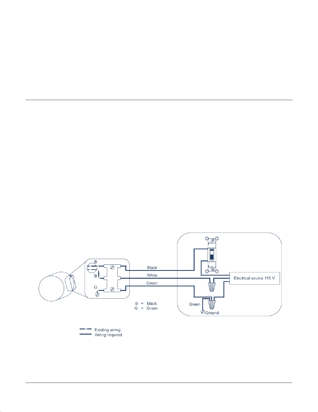
An electric cable will be necessary to supply power to the ventilator. In order to ensure rapid access for maintenance,
the cable must be installed and buried in a PVC pipe. The electric wiring of the vent must be done as demonstrated
in the diagram below. Please note that it is not necessary to have the air vent running all day; the on/off switch
shown on the diagram below may be replaced by a 24-hour mechanical timer (external installation) or a digital timer
(internal installation). For timer adjustment, please refer to the "Operation" section of this guide.
In order to connect the TLV-240 polyethylene tank, insert the ventilation ducts in 100 mm (4") diameter PVC rings,
on each side of the tank. During backfill, make sure the access lid is installed properly to avoid any material from
entering the tank. It is important that the soil, under the pipes and around the outlet, be well compacted to prevent
breakage or bending of parts subsequent to soil movement. Furthermore, it is essential to have full access inside
the ventilation tank for annual maintenance (or when necessary). Consequently, the lid must be accessible at all
times.

Premier Tech Aqua 3/3 TLV-240 –Installation and Operation Guide
Edition: 2017-08-09
4. Operation
The ventilator operation depends on the selected electrical installation. To control the ventilator, in the case of an
on/off switch, the switch must be permanently kept on the "ON" position, however in the case of a mechanical or
digital timer, the timer may be adjusted to stop the vent at night time. For example, a 16-hour working schedule
(6:00 AM to 10:00 PM) –8-hour interruption (10:00 PM to 6:00 AM) would insure proper ventilation of the biofilters
while lowering electrical consumption.
Since cold air may be harmful to the microorganisms present inside the Ecoflo®Biofilters, it is important to reduce
the ventilation time during the winter season.
5. Troubleshooting
The ventilator stops
It might be caused by a faulty adjustment of the timer, a breakage, a clogged ventilator or an electrical problem. The
following actions may help to identify the precise problem (in chronological order):
1–Make sure the switch is "ON" or, if the ventilator is controlled by a timer, that the switch is in working position
or that its adjustment is properly done. Make the necessary adjustments.
2 –Make sure the circuit breaker in the electrical panel that controls the vent is "ON". If not, put it back "ON".
3 –Shut off the circuit breaker. Open the TLV-240 lid (4 bolts) with a 9/16" wrench. Unscrew the collars of one of
the flexible reducing joints with a flat head screwdriver. Make the joint slide along the 100 mm (4") pipe and
verify if some residue is not blocking the ventilator.
4 –If none of these procedures succeed, please contact Premier Tech Aqua’s after-sales service.
6. Warranty
Premier Tech Aqua’s Ventilation System TLV-240 is guaranteed (vent and tank) against any defects (parts only) for
a period of one (1) year starting from the purchase date (proof of purchase required) if the system has been installed
and used according to the installation, operation and maintenance instructions as described in the present
Installation and Operation Guide. The warranty only covers the Ventilation System TLV-240 and does not extend to
peripheral equipments.
Exclusion
Premier Tech Aqua will not be liable for any damages, problems or expenses arising from inappropriate installation
or use of the product. This warranty will be null and void if product failure is caused by or arises from modifications,
faulty installation, improper usage or alterations.
The information contained in this document is based upon the latest information available at the time of publication and is designed
to provide you with a general introduction to our products. We make no warranties or representations as to its accuracy. We are
continually upda-ting and improving our products and reserve the right to amend, discontinue, alter or change specifications and
prices without prior notice.
© Premier Tech Ltd, 2016
Table of contents
Popular Fan manuals by other brands

Progress Lighting
Progress Lighting AirPro P250024 installation manual

Kichler Lighting
Kichler Lighting Botella instruction manual

LEGRAND
LEGRAND HPM RCFTRI12H4WE instruction sheet

Alnor
Alnor HRU-PremAIR-350 user manual

Monte Carlo Fan Company
Monte Carlo Fan Company 5BY52 Series Owner's guide and installation manual

MistCooling
MistCooling MST-MC32120 manual


