Dru Max Vent User manual

DRU VERWARMING B.V.
HOLLAND
INSTALLATIEHANDLEIDING NL/BE
INSTALLATIONSANLEITUNG DE/AT/BE/LU/CH
MANUEL D’INSTALLATION FR/BE/LU/CH
INSTALLATION MANUAL GB/IE
Bewaar dit document zorgvuldig
Bewahren Sie dieses Dokument sorgfältig auf
Conservez soigneusement cette notice
Please retain this document carefully
957.641.01
MAX VENT


NL/BE
Max Vent
1
INSTALLATIEHANDLEIDING
Woord vooraf
De installatiehandleiding geeft u de informatie die u nodig
hebt om het Max vent systeem zo te installeren dat het
goed en veilig functioneert.
U dient deze handleiding zorgvuldig te lezen en te gebrui-
ken. De afbeeldingen zijn achterin dit document opgeno-
men (Bijlage 1).
Na oplevering van het toestel dient u het document te
overhandigen aan de gebruiker.
1. Inleiding
Het Max vent systeem wordt geïnstalleerd op een Global
70 / Global 70 XT sfeer verwarmingstoestel om een
ruimte sneller te verwarmen en het comfort te verhogen.
Na inschakeling is een aangename, warme luchtstroom
voelbaar. Het Max vent systeem kan op hoog- of laagstand
draaien.
2. Uitpakken
Schenk aandacht aan de onderstaande punten bij
het uitpakken van het Max vent systeem:
• Controleer het systeem op transportschade.
• Neem zonodig contact op met DRU Service.
• Voer de verpakking af via de reguliere weg.
3. Installatie
!Let op - Installeer het Max vent systeem voordat
het toestel wordt geplaatst;
- Houd rekening met afwijkende inbouw-
maten bij toepassing van het Max vent
systeem (zie Afb. 1a en Afb. 1b);
- Monteer het bedieningspaneel nadat het
bedieningskastje in de boezem is ge-
plaatst.
-Vervang de verstelbare pootjes van het
verwarmingstoestel.
Volg de onderstaande stappen bij het installeren
(Afb. 2a t/m 2d):
• Vervang de verstelbare pootjes van het verwarmingstoe-
stel door de met de Maxvent meegeleverde exemplaren.
Let op: Leidingen en bedrading mogen niet geklemd
worden tussen vloer en Maxvent.
• Verwijder de doordrukplaatjes.
• Plaats de onderkast zonder deze vast te zetten.
• Plaats de bovenkast zodat de uitsparingen om de spijlen
aan de voorkant van het toestel vallen.
• Zet de bovenkast aan de voorkant vast met 4 zelfbo-
rende parkers.
• Zet de achterkant vast met m.b.v. zelfborende parkers.
• Controleer of de clixon aan de onderzijde contact maakt
met de branderplaat.
• Verbuig zonodig de beugel tot de clixon wel contact
maakt.
• Plaats de afdichtring rond de aansluitstomp.
• Zet vervolgens de montagering vast m.b.v. 4 parkers.
• Plaats het luchtrooster aan de voorkant.
• Monteer het bedieningspaneel bovenin het bedienings-
kastje m.b.v. de inbusbout.
• Sluit de elektrische bedrading aan op een 230V
aansluiting in de omgeving van het toestel (zie Afb. 3).
GEBRUIKERSINSTRUCTIE
1. Inleiding
Met de uitbreiding van het Max vent systeem op uw toestel
neemt uw comfort toe, omdat uw ruimte sneller wordt
opgewarmd. Na het inschakelen is een aangename, warme
luchtstroom voelbaar. Het systeem kan zowel op een
lage als op een hoge stand ingesteld worden.
2. Werking
In het bedieningskastje bevindt zich de schakelaar voor het
bedienen van uw Max vent systeem; zie Afb. 2b.
De schakelaar heeft een aan/uitstand (0), een laagstand (I)
en een hoogstand (II).
Na het inschakelen duurt het even voordat u een warme
luchtstroom voelt. De luchtstroom komt namelijk pas op
gang als het toestel voldoende warm is.
Als de schakelaar op “I” of “II” staat, treedt het Max vent
systeem automatisch in werking bij het inschakelen van uw
toestel.

2
INSTALLATIONSANLEITUNG
Vorwort
Die Installationsanleitung enthält die Informationen, die Sie
benötigen, um das Max-Vent-System so zu installieren,
dass es einwandfrei und sicher funktioniert.
Lesen Sie diese Installationsanleitung unbedingt sorgfältig
durch und halten Sie sich daran.
Die Abbildungen befinden sich hinten in diesem Dokument
(Anlage 1).
Nach der Übergabe des Geräts müssen Sie dem Benutzer
auch dieses Dokument überreichen.
1. Einleitung
Das Max-Vent-System wird auf einem Gasheizgerät vom Typ
Global 70 / Global 70 XT installiert, um einen Raum
schneller zu heizen und damit den Komfort zu erhöhen.
Nach dem Einschalten ist ein angenehmer, warmer Luft-
strom fühlbar. Das Max-Vent-System kann mit einer hohen
oder niedrigen Stufe laufen.
2. Auspacken
Beim Auspacken des Max-Vent-Systems sind folgen-
de Punkte zu beachten:
• Überprüfen Sie das System auf Transportschäden.
• Wenden Sie sich bei Bedarf an den DRU Service.
• Entsorgen Sie dieVerpackung auf dem üblichen Weg.
3. Installation
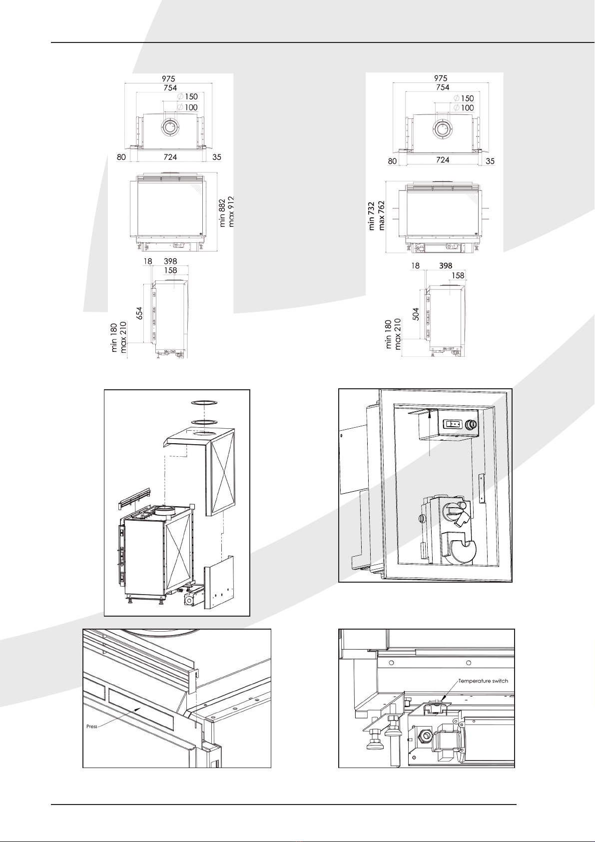
!Achtung - Installieren Sie das Max-Vent-System,
bevor das Gerät aufgestellt wird;
- Berücksichtigen Sie die abweichenden
Einbaumaße beiVerwendung des Max-
Vent-Systems (siehe Abb. 1a und Abb. 1b);
- Montieren Sie die Bedienungstafel, nach-
dem der Schaltkasten in den Kaminumbau
eingebaut wurde.
- Tausche die Unterstützungen des Heiz-
gerätes aus.
Gehen Sie beim Installieren wie folgt vor (Abb. 2a bis 2d):
• Tausche die einstellbare Unterstützungen des Heizgerä-
tes aus mit die mit Maxvent mitgelieferde Teilen.
Achtung: Leitungen und Bekabelung dürfen nicht einge-
klemmt werden zwischen Boden und Maxvent.
• Drücken Sie die vorgestanztenTeile heraus.
• Stellen Sie den Sockel an die richtige Stelle, ohne ihn zu
befestigen.
• Stellen Sie den Aufbau so hin, dass die Aussparungen um
die Stäbe an derVorderseite des Geräts fallen.
• Befestigen Sie den Aufbau an derVorderseite mit 4 selb-
stbohrenden Parkerschrauben.
• Befestigen Sie die Rückseite mit selbstbohrenden Parker-
schrauben.
• Kontrollieren Sie, ob der Klixon-Temperaturschalter
an der Unterseite einen Kontakt mit der Brennerplatte
herstellt.
• Verbiegen Sie den Bügel gegebenenfalls, bis der Klixon-
Temperaturschalter einen Kontakt herstellt.
• Legen Sie den Dichtungsring rund um den Anschluss-
Stutzen.
• Befestigen Sie anschließend den Montagering mit 4
Parkerschrauben.
• Setzen Sie den Lüftungsrost an derVorderseite ein.
• Montieren Sie die Bedienungstafel mit der Innensechs-
kantschraube oben im Schaltkasten.
• Schließen Sie die elektrischen Kabel an einen 230V-
Anschluss in der Nähe des Geräts an (siehe Abb. 3).
BEDIENUNGSANLEITUNG
1. Einleitung
Durch die Erweiterung Ihres Geräts mit dem Max-Vent-
System erhöht sich der Komfort, da der Raum schneller
erwärmt wird. Nach dem Einschalten ist ein angenehmer,
warmer Luftstrom fühlbar. Das System kann auf eine
niedrige oder hohe Stufe eingestellt werden.
2. Funktion
Im Schaltkasten befindet sich der Schalter für die Bedienung
Ihres Max-Vent-Systems; siehe Abb. 2b.
Der Schalter hat einen Ein-/Aus-Stand (0), eine niedrige
Stufe (I) und eine hohe Stufe (II).
Nach dem Einschalten dauert es etwas, bevor Sie einen
warmen Luftstrom fühlen. Der Luftstrom wird nämlich erst
in Gang gesetzt, wenn das Gerät warm genug ist.
Wenn der Schalter auf „I“ oder „II“ steht, wird das Max-
Vent-System beim Einschalten des Geräts automatisch
aktiviert.
DE/AT/BE/LU/CH

Max Vent
3
MANUEL D’INSTALLATION
Avant-propos
Le manuel d’installation contient les informations dont vous
avez besoin pour installer le système Max vent de manière
à ce qu’il fonctionne bien et en toute sécurité.
Veuillez lire attentivement le présent manuel et l’utiliser.
Les figures sont reprises à la fin du présent document
(Annexe 1).
Après livraison de l’appareil, veuillez remettre ce document
à l’utilisateur.
1. Introduction
Le système Max vent est installé sur un appareil de chauf-
fage d’ambiance au gaz Global 70 / Global 70 XT pour
chauffer
plus rapidement une pièce et augmenter le confort.
Une fois mis en marche, on perçoit un agréable flux d’air
chaud. Le système Max vent peut fonctionner en mode
d’intensité faible ou d’intensité élevée.
2. Déballage
Soyez attentif aux points suivants lorsque vous dé-
ballez le système Max vent:
• Contrôlez que le système n’a pas été endommagé du-
rant le transport.
• Si nécessaire, contactez le service après-vente DRU.
• Débarrassez-vous de l’emballage suivant les règles habi-
tuelles.
3. Installation
!Attention - Installez le système Max vent avant que
l’appareil ne soit mis en place;
- Tenez compte des mesures
d’encastrement différentes en cas
d’application du système Max vent
est appliqué (voir les Fig. 1a et 1b);
- Montez le panneau de commande après
que le coffret de commande ait été placé
dans le manteau de cheminée.
- Enchangez les supports de l’appareille de
chaufflage.
Procédez comme suit pour l’installation (Fig. 2a à 2d):
• Enchangez les supports ajustable avec les pieces livrées
avec le Maxvent.
Attention: n’encastres pas les fils ou tubes entre le sol
et le Maxvent.
• Retirez les plaquettes alvéolées.
• Placez le caisson inférieur sans le fixer.
• Placez le caisson supérieur de manière à ce que les
entailles autour des barres se trouvent à l’avant de
l’appareil.
• Fixez le caisson supérieur à l’avant avec 4 vis Parker
autoperceuses.
• Fixez la face arrière à l’aide de vis Parker autoperceuses.
• Contrôlez si le clixon sur la face inférieure fait contact
avec la plaque du brûleur.
• Si nécessaire, courbez son support jusqu’à ce que le
clixon face bien contact.
• Placez le joint autour de la buse de raccordement.
• Fixez ensuite la bague de montage à l’aide de 4 vis Par-
ker.
• Placez la grille d’aération à l’avant.
• Montez le panneau de commande dans le haut du coffret
de commande à l’aide du boulon hexagonal.
• Connectez le câble électrique sur une alimentation
230V proche de l’appareil (voir la Fig. 3).
MODE D’EMPLOI
1. Einleitung
En installant l’extension du système Max vent sur votre ap-
pareil, vous augmentez votre confort car votre pièce est
chauffée plus rapidement.Après sa mise en marche, vous
percevez un agréable flux d’air chaud. Le système peut être
réglé sur une intensité faible ou une intensité plus élevée.
2. Fonctionnement
L’interrupteur permettant d’actionner votre système Max
vent se trouve dans le coffret de commande ; voir la Fig. 2b.
Cet interrupteur dispose d’une position marche/arrêt (0),
et d’une position de faible intensité (I) et une position de
densité élevée (II).
Après sa mise en marche, un instant suffit pour que vous
perceviez un flux d’air chaud. Ce flux d’air chaud se produit
en effet lorsque l’appareil est suffisamment chaud.
Si l’interrupteur se trouve sur “I” ou “II”, le système Max
vent se met automatiquement en marche lorsque l’appareil
est allumé.
FR/BE/LU/CH

4
INSTALLATION MANUAL
Preface
The installation manual will give you the information you
need to install the Max vent system in such a way that it
will operate properly and safely.
Please read and use this manual carefully.
The figures are included at the back of this document
(Appendix 1).
After delivery of the appliance, you must give the document
to the user.
1. Introduction
The Max vent system must be installed on a Global 70
/ Global 70 XT atmospheric gas-fired heating appliance
in order to heat the room more quickly and to increase
comfort.
After it has been switched on, you can sense a pleasant,
warm air flow.The Max vent system can operate at a high
or low position.
2. Removing the packaging
Note the following items when removing the packa-
ging of the Max vent system:
• Check the system for damages during transport.
• If necessary, contact DRU Service.
• Dispose of packaging in accordance with local
regulations.
3. Installation
!Caution - Fit the Max vent system before the ap-
pliance is placed;
- Take the different construction measu-
rements into account when applying the
Max vent system (see fig. 1a and fig. 1b);
- Mount the control panel after placing the
control box in the chimney breast.
- Replace supports of the heating appliance.
Observe the following steps during installation
(fig. 2a to 2d):
• Replace the adjustable supports of the heating appliance
by the with the Maxvent supplied pieces.
Notice: Tubes and wires may not be clamped of
between floor and Maxvent.
• Remove the knock-outs.
• Place the lower box without fixing it.
• Place the top box in such a way that the notches fit
around the bars at the front of the appliance.
• Attach the top box at the front using 4 self-tapping
screws.
• Attach the rear using self-tapping screws.
• Check if the clixon at the bottom is making contact with
the burner plate.
• If necessary, bend the bracket until the clixon does make
contact.
• Place the sealing ring around the connection stump.
• Then, fix the mounting ring using 4 self-tapping screws.
• Place the air grate at the front.
• Mount the control panel in the top of the control box
using the socket cap screw.
• Connect the electric wiring to a 230V connection near
the appliance (see fig. 3).
USER INSTRUCTIONS
1. Introduction
By extending your appliance with the Max vent system,
you will feel more comfortable, because the room will be
heated more quickly. After it has been switched on, you can
sense a pleasant, warm air flow.The system can be set at a
low or a high position.
2. Operation
In the control box you will find the switch that allows you
to operate your Max vent system; see fig. 2b.
The switch has an on/off position (0), a low position (I) and
a high position (II).
After it has been switched on, it will take a moment before
you can feel a warm air flow.The air flow will only begin
once the appliance has been sufficiently heated.
If the switch is on position “I” or “II”, the Max vent system
will start operating automatically when you switch on your
appliance.
GB/IE

5
APPENDIX 1:AFBEELDINGEN/ABBILDUNGEN/FIGURES
Max Vent
1b Global 70XT BF1a Global 70 BF
2a
2c 2d
2b
957.641.00

6
APPENDIX 2:AFBEELDINGEN/ABBILDUNGEN/FIGURES
Fuse
250 mA
M
Fan
NL
Silicon cable
Silicon cable
Brown cable
Yellow/Green cable
Yellow/Green cable
Black cable
Grey cable
Blue cable Brown cable
Brown cable
I
II
Main Switch
Off
(1mm2)
(1mm2)
Clicon NO
36˚C
3. ELECTRICAL SCHEME MAX VENT
Table of contents
Languages:
Other Dru Fan manuals
Popular Fan manuals by other brands

Field Controls
Field Controls 46334200 instruction sheet

Chore-Time
Chore-Time Endura 56911 Series Installation and operator's manual

dyras
dyras TF-16WIFI instruction manual

Greenheck
Greenheck SSDFD-155 Specification sheet

Anslut
Anslut 412-004 operating instructions

Sharper Image
Sharper Image REFRESH 06 owner's guide