manuals.online logo
Brands
  1. Home
  2. •
  3. Brands
  4. •
  5. Eglo
  6. •
  7. Fan
  8. •
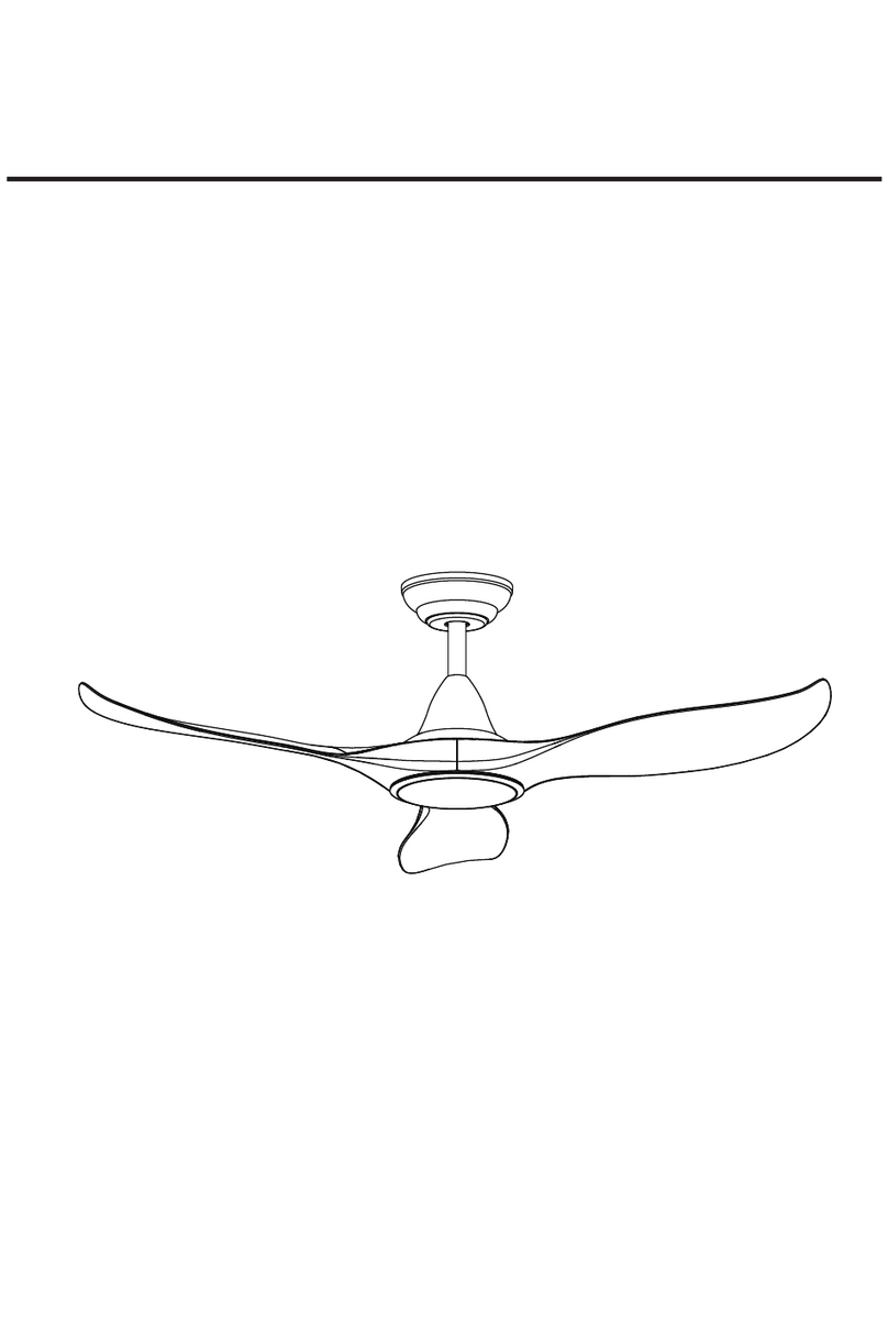
  9. Eglo 40 Degree Canopy User manual

Eglo 40 Degree Canopy User manual

Downrod not included
Do not dispose of electrical appliances as unsorted municipal waste, use separate collection facilities. Contact your local council for
more information regarding the collection systems available. If electrical appliances are disposed of in landfills or dumps, hazardous
substances can leak into the ground water and get into the food chain, damaging your health and well-being.
EGLO Lighting has a policy of continual product improvement and development, dimensions, hardware and designs may change to reflect
this policy. EGLO reserves the right to discontinue or change product specifications & designs at any time without notice and without
incurring obligations. The images including all features and specifications in this manual are for illustrative purposes only. Product details,
images & line drawings may vary depending on specific product models.
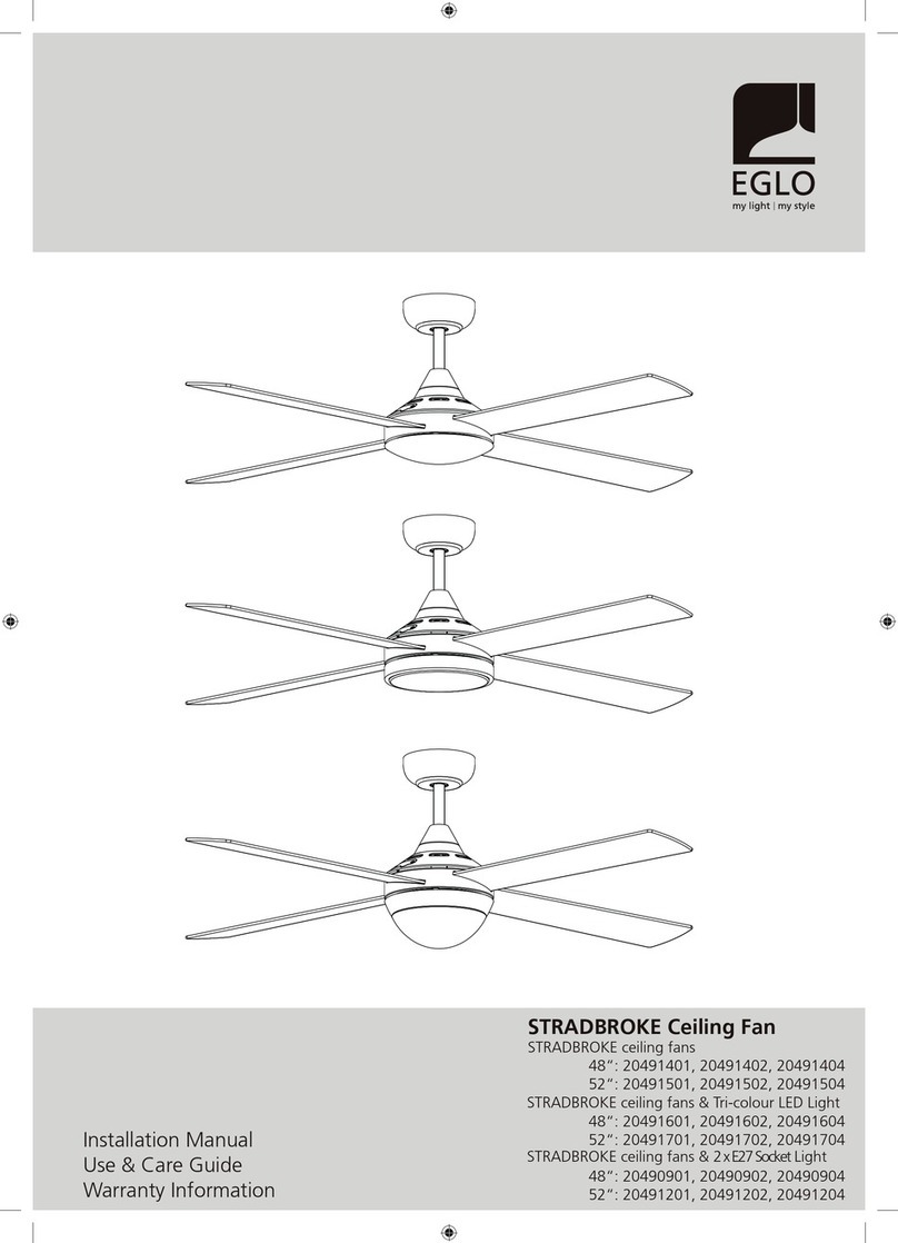
40 Degree Canopy
20557501, 20557502, 20557504, 20557512
*Suitable for use with compable
EGLO ceiling fan models only
Installation Manual
Use & Care Guide
Warranty Information
FOR YOUR SAFETY:
1. The xing point for your ceiling fan must be of sound construcon, undamaged, and capable of supporng a load of 35Kg, or 4 times the
weight of the fan plus the method of aachment, whichever is greater.
2. Care needs to be taken to ensure the installaon locaon does not allow the fan blades to come into contact with any object or surface.
There must be a minimum of 60cm clearance between the blade p (end) and the nearest wall or object. Reduced clearances to walls or
ceiling can not only reduce the amount of air your fan can move, but also cause your fan to de-stabilise.
3. The installaon should also allow for a clearance of 2.1m between the oor and the boom of the blades. The installaon should allow for
a minimum of 3.0m between ceiling fans.
4. The fan and the hanging bracket must be earthed.
PARTSLIST:
INSTALLATION:
Note:The fixing screws included are designed for use with mber ceiling joists, for all other materials, the appropriate fixing
screws will need to be purchased separately.
Important: When mounted on angled/sloped ceilings, the hanger bracket must be installed so that the opening is facing across the
direcon of ceiling pitch. This angle ceiling bracket must only be used on a maximum 40 degree sloped ceiling pitch, and must have
a minimum of 60cm clearance from the lower side of the ceiling to the edge of the fan blade. It would be expected that in many
installaons, and extension downrod will need to be purchased separately.
IMPORTANT: Check that the power is disconnected and/or the mains switched off at the
circuit box to ensure all pole isola�on of the power supply.
40 Deg. Canopy Ceiling Fan Accessory2
A: Mou ng Bracket
B: Canopy
C: Hanger ball
D: Hanger Ball Insert - 26.5mm downrods
E: Hanger Ball Insert – 21.0mm downrods
F: Hanger Ball Pin
G: Receiver Shelf
H: Wood Screws & Washers
Note: Remove the hanger ball from your exi downrod assembly by
removing the screw, lowering the hanger ball, and removing the pin,
before sliding the hanger ball othe downrod.
Important:
Select the correct size hanger ball insert ,
according to the diameter of the downrod on the fan being installed.
1 2
3 4
x 2 H
A
C
ABC
DE
x 1 x 1
x 1
x 1 x 1 Fx 1
x 2
H
Gx 1
C
D E
or
Downrod
(Not inclued)
C
Pin
D E
or
WARNING: An all-pole disconnecon MUST be incorporated into the xed wiring in accordance with the wiring rules, as outlined in clause 7.12.2 of
AS/NZS 60335-1 for meeng the minimum electrical safety of this standard. Please note warranty will be void if the installaon is without a means
for an all-pole disconnecon incorporated in the xed wiring in accordance with the wiring rules.
WIRING CONNECTIONS:
WARNING:
FOR YOUR SAFETY ALL ELECTRICAL CONNECTIONS MUST ONLY
BE UNDERTAKEN BY A QUALIFIED AND LICENSED ELECTRICIAN.
1. Connect the receiver to the fan/light as per ceiling fan manual.
2. Using the wiring harness from the terminal block/hanger bracket of the original hanger bracket supplied with the fan,
connect to the 40 degree mounting bracket quick connect terminals.
3. Connect AC input.
A single pole isolaon switch must be also placed in the same room as the fan as per local wiring regulaons AS/NZS 3000, in accordance with clause
2.3.2.2.1& 4.13.1.3 of AS/NZS 3000.
Note: If there are two or more ceiling fans installed in the one locaon/room, an isolaon switch is required for EACH celling fan. This is required
when programming any remote-control transmier & receiver to pair together, and for fan servicing.
3 40 Deg. Canopy Ceiling Fan Accessory
G
Receiver (If Fitted)
5 6
7 8
B
COMMERCIAL USE:
This product is warranted for commercial applications.
MAINTENANCE:
Ceiling fans natural movement can cause screws to loosen. Every 6 months, check that ALL screws are securely tightened with a
screwdriver including the set screws in the hanger ball.
REPLACEMENT WARRANTY:
EGLO offers the original purchaser a replacement of the EGLO product in cases where the product fails due to defective
materials or workmanship, when installed and operated under normal domestic/residential conditions for 1 year. The warranty period
begins from the date of purchase.
You must provide proof of purchase (such as the original dated purchase receipt/invoice) from an authorised EGLO reseller to make a
warranty claim. You must also provide a receipt from installation, including the electrical contractors licence number - if an electrical
licence number cannot be supplied, your claim will be denied. This warranty will not apply if the ceiling fan is installed by anyone other
than a qualified and licensed electrical contractor.
REPAIRS / REPLACEMENTS
EGLO products presented for repair may be replaced by refurbished goods of the same type rather than being
repaired at the discretion of EGLO. Refurbished parts may be used to repair the goods to proper order.
BALANCE OF WARRANTY
To the maximum extent permitted by law, any product replaced, repaired or refurbished by EGLO is covered only
by the balance of the warranty period remaining from the date of original purchase of the original EGLO product.
EGLO Lighting (EGLO) will not be liable for charges incurred by the consumer for rectification, deinstallation or reinstallation unless
approved by EGLO management in writing.
For all warranty enquiries, please phone the EGLO Customer Care hotline directly on 1800 254 448 or email warranty@eglolighting.
com.au, along with your details, proof of purchase & proof of electrical installation (including electrical contractor licence number), and
the nature of the problem.
WHAT IS NOT COVERED:
Subject to “Your Consumer Rights“, but otherwise to the maximum extent permitted by law, the EGLO warranties provided in this
document will not cover the following:
1. EGLO products that are not purchased from an authorised retailer and installed in Australia.
2. Where installation was not carried out by a qualified and licensed electrical contractor or where a valid Electrical Safety Certificate
or installers invoice with licence number cannot be presented.
3. Defect, damage or failure to a EGLO product resulting from misuse, accident, neglect, abuse, tampering, modifications or unautho-
rised repairs of any kind by any person.
4. Damages not caused by a fault in the EGLO product materials or workmanship.
5. Transportation and in-transit insurance costs, if the product or parts thereof have to be returned for repair or replacement to the
retailer or the authorised service agent.
6. Faults deemed caused by a lack of regular maintenance, e.g. screws and nuts becoming loose.
EGLO Lighng Australia
5/339 Archereld Road Richlands
Queensland 4077
www.eglo.com.au

This manual suits for next models

4

Other Eglo Fan manuals

Eglo Whitehaven 203229A User manual

Eglo

Eglo Whitehaven 203229A User manual

Eglo Petani 203233A User manual

Eglo

Eglo Petani 203233A User manual

Eglo BONDI 1 User manual

Eglo

Eglo BONDI 1 User manual

Eglo TIGGANO 35039 User manual

Eglo

Eglo TIGGANO 35039 User manual

Eglo NEVIS 202748 User manual

Eglo

Eglo NEVIS 202748 User manual

Eglo 203227A User manual

Eglo

Eglo 203227A User manual

Eglo TOURBILLION User manual

Eglo

Eglo TOURBILLION User manual

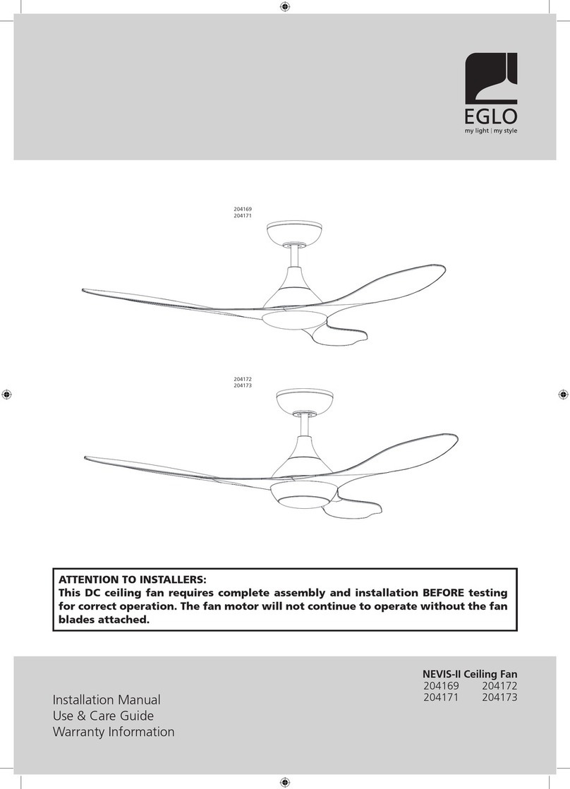
Eglo NEVIS-II User manual

Eglo

Eglo NEVIS-II User manual

Eglo Casou User manual
Eglo

Eglo Casou User manual

Eglo SUSALE User manual

Eglo

Eglo SUSALE User manual

Eglo MOSTEIROS 35004 User manual

Eglo

Eglo MOSTEIROS 35004 User manual

Eglo STRADBROKE User manual

Eglo

Eglo STRADBROKE User manual

Eglo NOOSA Series User manual

Eglo

Eglo NOOSA Series User manual

Eglo TIGGANO 35181 User manual

Eglo

Eglo TIGGANO 35181 User manual

Eglo HOI AN 35027 User manual

Eglo

Eglo HOI AN 35027 User manual

Eglo GELSINA User manual

Eglo

Eglo GELSINA User manual

Eglo TORQUAY User manual

Eglo

Eglo TORQUAY User manual

Eglo SEACLIFF 20523401 Instruction Manual

Eglo

Eglo SEACLIFF 20523401 Instruction Manual

Eglo ORTONA 35095 User manual

Eglo

Eglo ORTONA 35095 User manual

Eglo SURF 20549701 User manual

Eglo

Eglo SURF 20549701 User manual

Eglo TIROL User manual

Eglo

Eglo TIROL User manual

Eglo BONDI Series User manual

Eglo

Eglo BONDI Series User manual

Popular Fan manuals by other brands

Hunter 90400 owner's guide

Hunter

Hunter 90400 owner's guide

Vent-A-Garage VG100 manual

Vent-A-Garage

Vent-A-Garage VG100 manual

Harbor Breeze E-WCK44ABZ5LKS manual

Harbor Breeze

Harbor Breeze E-WCK44ABZ5LKS manual

Panasonic FY-E15DZ1 operation instruction

Panasonic

Panasonic FY-E15DZ1 operation instruction

ZIEHL-ABEGG ECblue Assembly instructions

ZIEHL-ABEGG

ZIEHL-ABEGG ECblue Assembly instructions

Greenheck RSF Installation, operation and maintenance manual

Greenheck

Greenheck RSF Installation, operation and maintenance manual

Orcon HRC-EcoSmart user guide

Orcon

Orcon HRC-EcoSmart user guide

YASKAWA AC Drive manual

YASKAWA

YASKAWA AC Drive manual

atomi smart AT2123 quick start guide

atomi smart

atomi smart AT2123 quick start guide

Omega Altise OT120B Operation, maintenance and safety instructions

Omega Altise

Omega Altise OT120B Operation, maintenance and safety instructions

Hunter 83002 Sona owner's manual

Hunter

Hunter 83002 Sona owner's manual

Honeywell PERFECT WINDOW HR150 Product data

Honeywell

Honeywell PERFECT WINDOW HR150 Product data

Zoo Fans H25 operating manual

Zoo Fans

Zoo Fans H25 operating manual

Casablanca 55035 Owner's guide and installation manual

Casablanca

Casablanca 55035 Owner's guide and installation manual

Broan Losone Select L400KL manual

Broan

Broan Losone Select L400KL manual

Be Cool BC40MSTF2205SS manual

Be Cool

Be Cool BC40MSTF2205SS manual

Marta MT-FN2537 user manual

Marta

Marta MT-FN2537 user manual

Swegon ADAPT Extract d Installation, commissioning maintenance

Swegon

Swegon ADAPT Extract d Installation, commissioning maintenance

manuals.online logo
manuals.online logoBrands
  • About & Mission
  • Contact us
  • Privacy Policy
  • Terms and Conditions

Copyright 2025 Manuals.Online. All Rights Reserved.