Prevelo Alpha Zero User manual

1
OWNER’S MANUAL
ENGLISH
™

2

3
CONTENTS
WELCOME 5
ALPHA ZERO ASSEMBLY 6
ALPHA ONE AND ALPHA TWO ASSEMBLY 8
ALPHA THREE AND ALPHA FOUR ASSEMBLY 12
ZULU THREE AND ZULU FOUR ASSEMBLY 18
BIKE FIT 23
PRE-RIDE CHECK 24
BASIC SAFETY 25
USE AND DESIGN 28
MAINTENANCE & CARE 29

4
IMPORTANT
This manual contains important safety, performance and service information.
Read it before you take the first ride on your new bicycle, and keep it for
reference.
Additional safety, performance and service information for specific
components such as suspension or pedals on your bicycle, or for accessories
such as helmets or lights that you purchase, may also be available. Make sure
that you have obtained all the manufacturers’ literature that was included with
your bicycle and/or accessories. In case of a conflict between the instructions in
this manual and information provided by a component manufacturer, always
follow the component manufacturer’s instructions. If you have any questions
or do not understand something, take responsibility for your safety and consult
with your dealer or the bicycle’s manufacturer.
NOTE: This manual is not intended as a comprehensive use, service, repair or
maintenance manual. Please consult a bicycle professional or contact us at
(805) 557-8300 or www.prevelobikes.com for questions about repairs and
maintenance.

5
Congratulations on the purchase of your new Prevelo Bike! Excited yet? There are
just a few steps needed before your little cyclist can begin a lifelong cycling journey.
• JOIN the Prevelo Bikes Family on our Facebook page at
facebook.com/prevelobikes. This can ensure you stay up to date on any news
and special events. It’s also a great way to share pictures of your kiddos being
awesome little cyclists!
• READ this Owner Manual in its entirety. For additional information, you can also
reference our website, prevelobikes.com.
• ASSEMBLE your new bike per the Assembly Instructions included with your bike.
Don’t worry, it’s super easy.
WELCOME
6
ALPHA ZERO ASSEMBLY
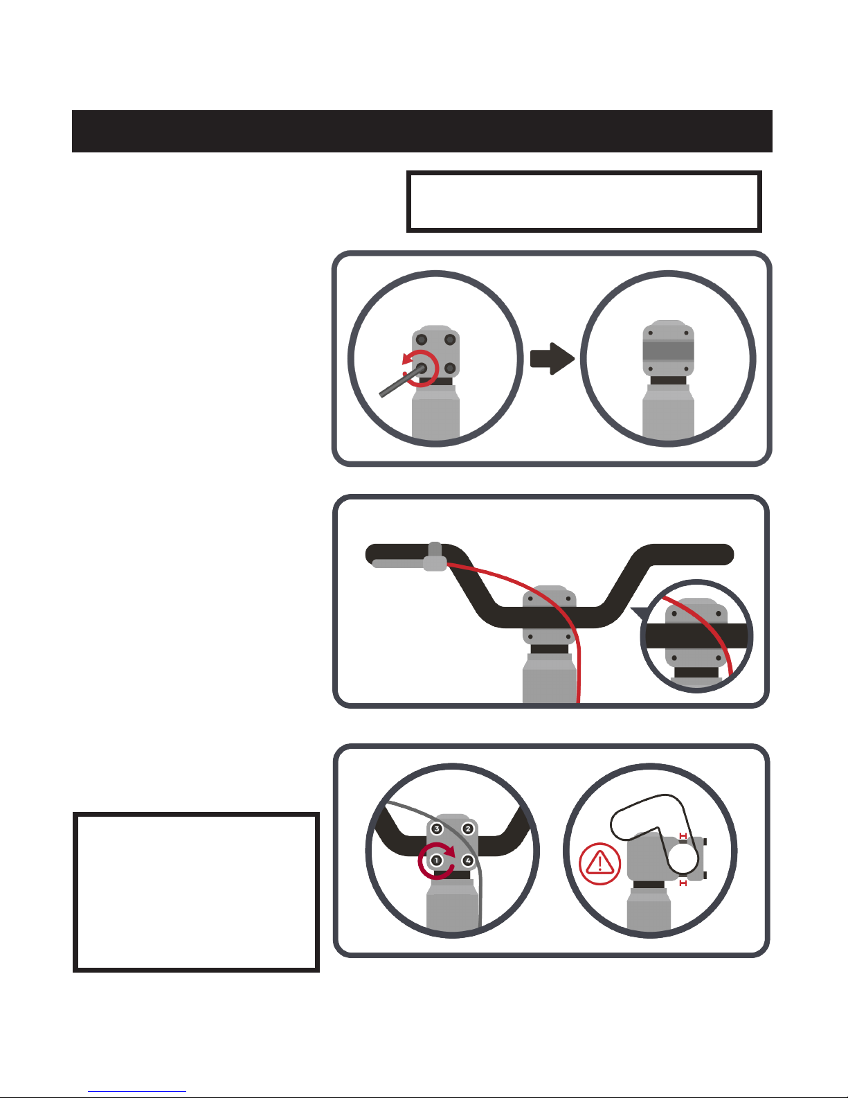
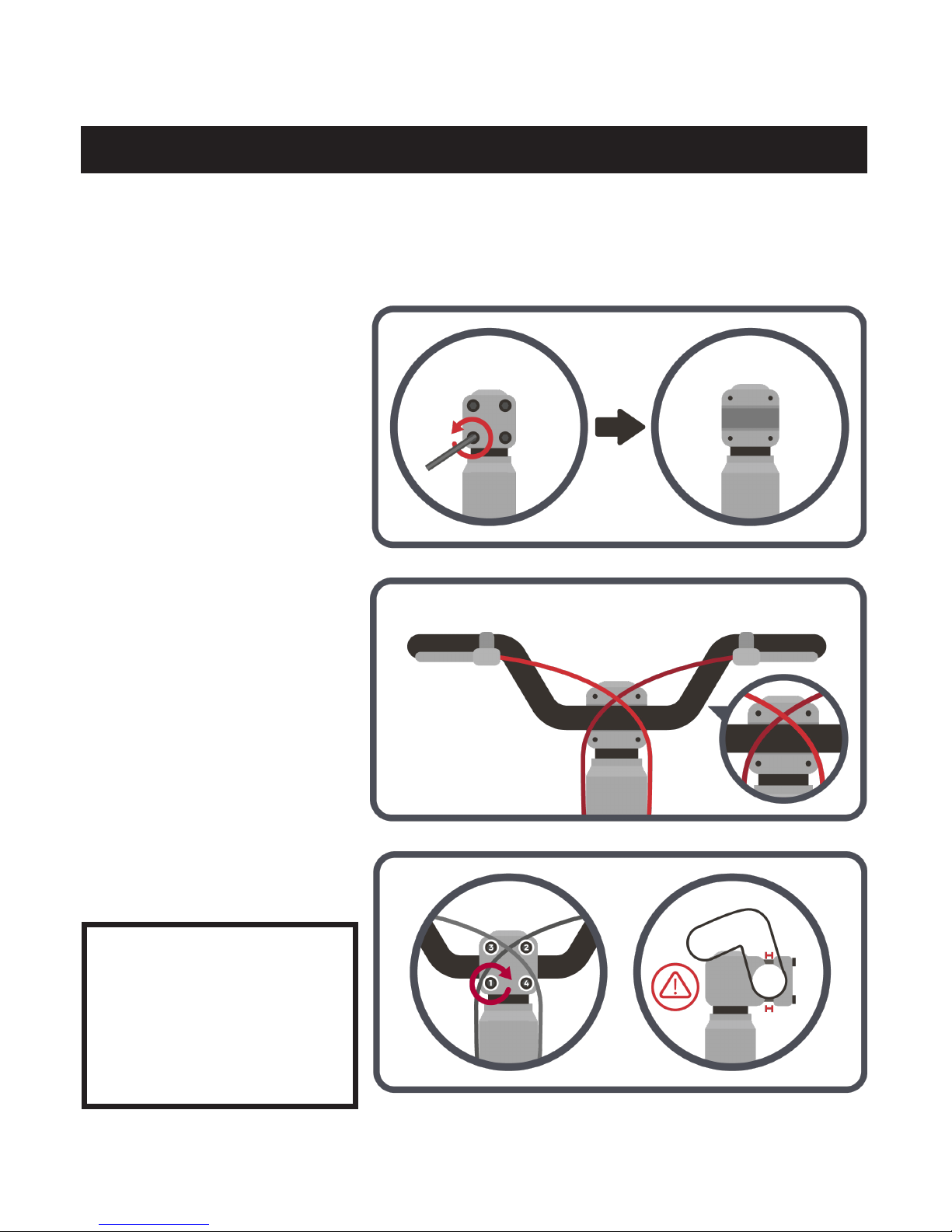
Step 1: Attach Handle Bar to Stem
Using the supplied 5mm hex
key, unscrew the four bolts
holding the stem face plate to
the stem and remove the stem
face plate.
Position the handlebars on the
stem. Center the handlebars.
Make sure the cables are on the
front of the bike as illustrated.
Reattach the stem face plate
with the four bolts. Use the
supplied 5MM wrench to tighten
firmly (6NM of torque).
NOTE: Tighten the bolts in
an X pattern as illustrated.
As you tighten, pay attention
to the gap between the stem
and stem face plate. The gap
on the top should be even
with the gap on the bottom.
Alpha Zero Recommended for ages 1½ to 4
years. Adult assembly required.

7
ALPHA ZERO ASSEMBLY
Step 2: Adjust Seat Height
Release the seat tube quick release by
pulling the lever to the right side of the bike.
Adjust the seat height.
Close the quick release lever completely.
NOTE: If the seat post clamp is either too
tight or too loose, adjust tightness using
the bolt on the left side of the clamp.
For balance bike fit, Prevelo recommends
the seat height be adjusted so, while
seated in the saddle, the rider can get
both feet flat on the ground with a slight
bend in the knee.

8
ALPHA ONE AND ALPHA TWO ASSEMBLY
Step 1: Attach Handle Bar to Stem
Using the supplied 5mm hex
key, unscrew the four bolts
holding the stem face plate to
the stem and remove the stem
face plate.
Position the handlebars on the
stem. Center the handlebars.
Make sure the cables are on the
front of the bike as illustrated.
Reattach the stem face plate
with the four bolts. Use the
supplied 5MM wrench to tighten
firmly (6NM of torque).
NOTE: Tighten the bolts in
an X pattern as illustrated.
As you tighten, pay attention
to the gap between the stem
and stem face plate. The gap
on the top should be even
with the gap on the bottom.
9
ALPHA ONE AND ALPHA TWO ASSEMBLY
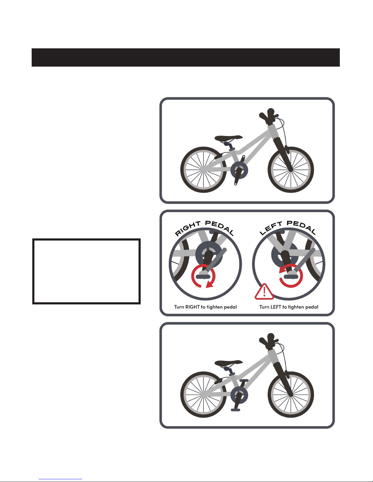
Step 2: Attach Pedals
Screw the pedals into the pedal
holes in the crank arms and
tighten with the supplied 15mm
wrench.
NOTE: The pedals come
labeled with “R” and “L”
stickers to indicate right and
left. The left pedal is reverse
threaded and must be turned
counterclockwise to tighten.

10
ALPHA ONE AND ALPHA TWO ASSEMBLY
Step 3: Adjust Seat Height
Release the seat tube quick release by
pulling the lever to the right side of the bike.
Adjust the seat height.
Close the quick release lever completely.
NOTE: If the seat post clamp is either too
tight or too loose, adjust tightness using
the bolt on the left side of the clamp.
For advice on seat height, please see the
fit guide on page 23.

11

12
ALPHA THREE AND ALPHA FOUR ASSEMBLY
Step 1: Attach Handle Bar to Stem
Using the supplied 5mm hex
key, unscrew the four bolts
holding the stem face plate to
the stem and remove the stem
face plate.
Position the handlebars on the
stem. Center the handlebars.
Make sure the cables are on the
front of the bike as illustrated.
Reattach the stem face plate
with the four bolts. Use the
supplied 4MM wrench to tighten
firmly (observe torque labeled
on stem).
NOTE: Tighten the bolts in
an X pattern as illustrated.
As you tighten, pay attention
to the gap between the stem
and stem face plate. The gap
on the top should be even
with the gap on the bottom.
13
ALPHA THREE AND ALPHA FOUR ASSEMBLY
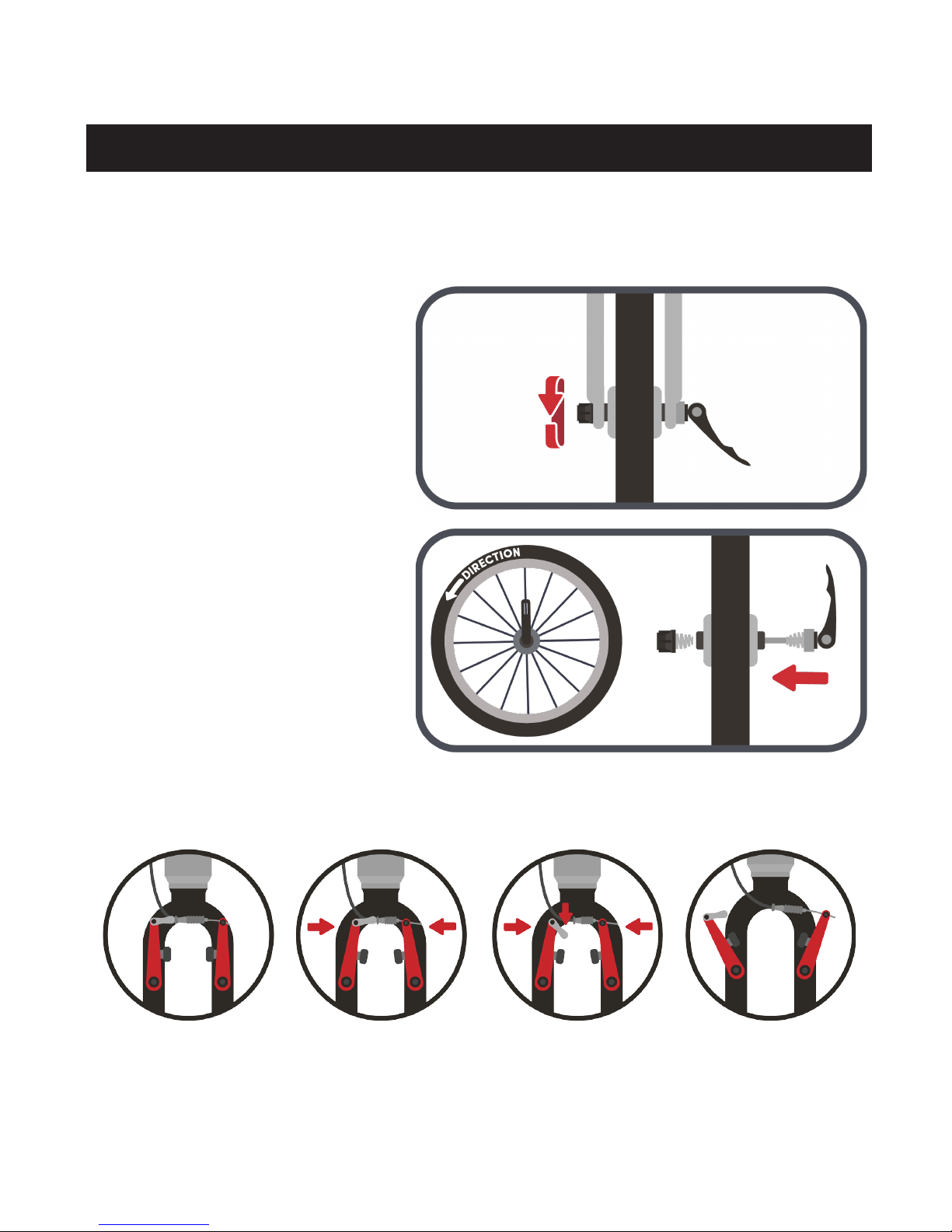
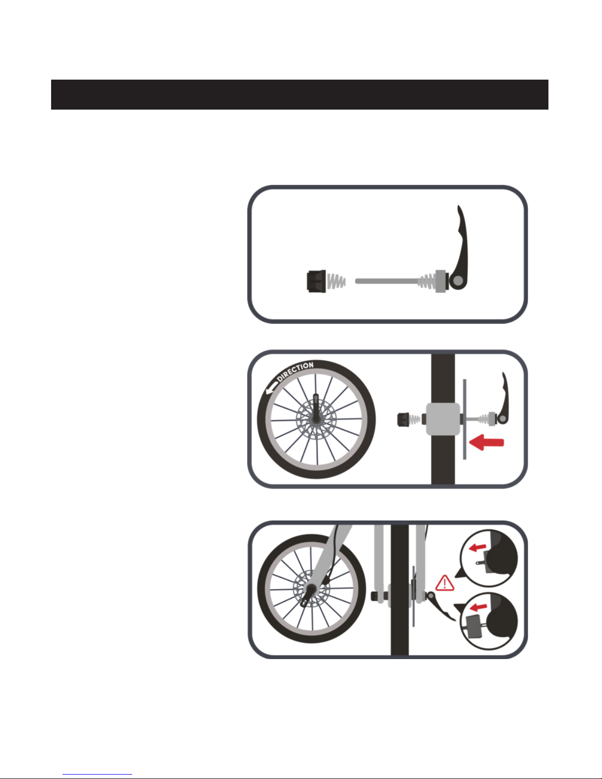
Step 2: Attach Front Wheel
Locate the quick release
assembly. Remove the nut and
one of the springs.
Find the arrow indicating
direction of rotation on the
front tire. Lay the wheel on a
flat surface so that the arrow
indicates a counter-clockwise
rotation. Insert the quick release
skewer through the hub. Put the
spring and nut on the opposite
side of the hub. Keep the entire
assembly loose for now.
Disengage the front brake calipers.
14
ALPHA THREE AND ALPHA FOUR ASSEMBLY
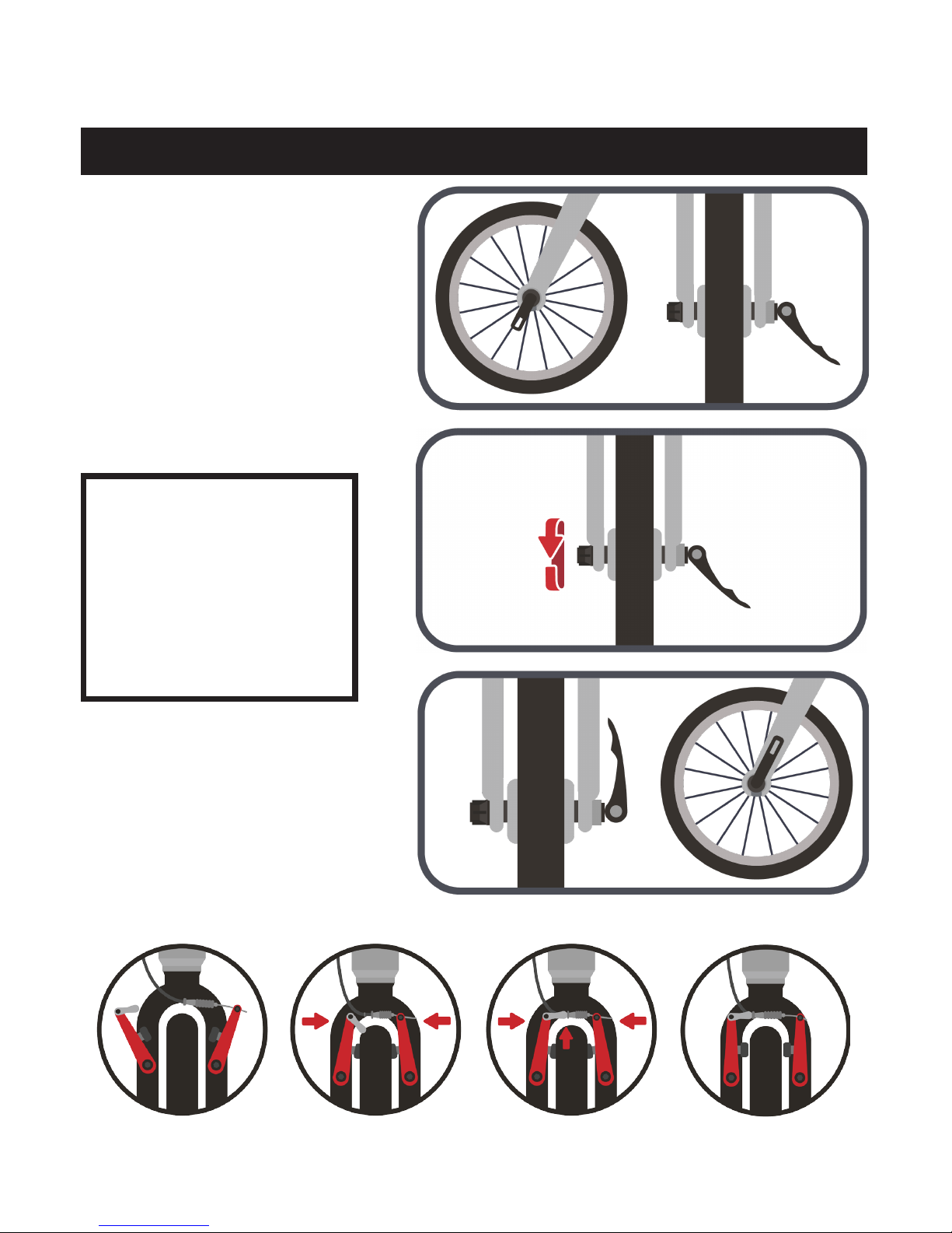
Reattached the front brake caliper.
FULLY insert the wheel assembly
into the dropouts at the bottom
of the front fork. The quick
release handle should be on the
left side of the bike (from the
rider’s perspective).
Tighten by turning the nut on
the right side of the skewer until
slightly snug.
IMPORTANT: Make sure
that (1) both sides of the front
axle are fully inserted into the
front dropouts and (2) the
nut on the right side and the
quick release washer on the
left side are FULLY SEATED
inside the raised lips on the
dropouts.
Tighten the quick release lever
completely by pushing it up
towards the fork. If the quick
release lever feels too tight or
too loose, adjust using the nut
on the right side of the axle.

15
ALPHA THREE AND ALPHA FOUR ASSEMBLY
Step 3: Attach Pedals
Screw the pedals into the pedal
holes in the crank arms and
tighten with the supplied 15mm
wrench.
NOTE: The pedals come
labeled with “R” and “L”
stickers to indicate right and
left. The left pedal is reverse
threaded and must be turned
counterclockwise to tighten.

16
ALPHA THREE AND ALPHA FOUR ASSEMBLY
Step 4: Adjust Seat Height
Release the seat tube quick release by
pulling the lever to the right side of the bike.
Adjust the seat height.
Close the quick release lever completely.
NOTE: If the seat post clamp is either too
tight or too loose, adjust tightness using
the bolt on the left side of the clamp.
For advice on seat height, please see the
fit guide on page 23.

17
18
ZULU THREE AND ZULU FOUR ASSEMBLY
Step 1: Attach Handle Bar to Stem
Using the supplied 5mm hex
key, unscrew the four bolts
holding the stem face plate to
the stem and remove the stem
face plate.
Position the handlebars on the
stem. Center the handlebars.
Make sure the cables are on the
front of the bike as illustrated.
Reattach the stem face plate
with the four bolts. Use the
supplied 4MM wrench to tighten
firmly (observe torque labeled
on stem).
NOTE: Tighten the bolts in
an X pattern as illustrated.
As you tighten, pay attention
to the gap between the stem
and stem face plate. The gap
on the top should be even
with the gap on the bottom.
19
ZULU THREE AND ZULU FOUR ASSEMBLY
Step 2: Attach Front Wheel
Locate the quick release
assembly. Remove the nut and
one of the springs.
Find the arrow indicating
direction of rotation on the
front tire. Lay the wheel on a
flat surface so that the arrow
indicates a counter-clockwise
rotation. Insert the quick release
skewer through the hub. Put the
spring and nut on the opposite
side of the hub. Keep the entire
assembly loose for now.
If this is the first time installing
the wheel on the bike, the brake
pads will have a black plastic
spacer between them. Remove
the black spacer. After the
spacer is removed, do not pull
the front brake lever until the
wheel is installed. If the front
brake lever is pulled without
a spacer or wheel in place
the brake pads can squeeze
together and will need to be
separated again before the
wheel can be installed.

20
FULLY insert the wheel assembly
into the dropouts at the bottom of
the front fork. The quick release
handle should be on the left
side of the bike (from the rider’s
perspective). Make sure that the
brake rotor slides between the
brake pads. If the brake pads are
compressed too close together,
gently push them apart using a
credit card, flat head screw driver
or a butter knife (But don’t use a
sharp knife!)
Tighten by turning the nut on
the right side of the skewer until
slightly snug.
IMPORTANT: Make sure
that (1) both sides of the front
axle are fully inserted into the
front dropouts and (2) the
nut on the right side and the
quick release washer on the
left side are FULLY SEATED
inside the raised lips on the
dropouts.
Tighten the quick release lever
completely by pushing it up
towards the fork. If the quick
release lever feels too tight or
too loose, adjust using the nut
on the right side of the axle.
ZULU THREE AND ZULU FOUR ASSEMBLY
Table of contents
Popular Bicycle manuals by other brands


Rockler
Rockler Blum Tandem Edge Blumotion Drawer Slide instructions

Look
Look 795 LIGHT RS manual

Lightning Bicycle
Lightning Bicycle P-38 Assembly and operation manual

Invacare
Invacare Top End Force G COMPONENT VERIFICATION CHECKLIST AND ASSEMBLY INSTRUCTIONS

NAKTO
NAKTO Classic Assembly instructions

KIKKA BOO
KIKKA BOO GIOVI Instructions for use


