PRIAM DISKOS 3450 User manual

OEM/SERVICE MANUAL
DISKOS 3450
DISKOS 7050
EIGHT INCH
WINCHESTER
DISC DRIVES

IPIRllAM
a-Inch
Winchester
Disc
Drives
OEM/Service
Manual
JULY
1982

IPRllAM
a-Inch
Winchester
Disc
Drives
OEM/Service
Manual
Changes
to
this
Manual
This manual
will
be changed
periodically
to
keep
it
current
with
improvements as we make them.
Changes
start
with
Field Engineering
Bulletins
that
alert field service
technicians
to
critical
prob-
lem areas and changes in maintenance procedures.
After
aseries
of
these notes are issued
or
acriti-
cal one is issued, we
will
publish
changed pages,
which
are the remove-the-old and insert-the-new
type. Avertical bar in the margin
of
the changed
page
indicates
the revised material.
After
about
20%
of
the
manual's
pages are changed, we
will
reissue the entire manual. When PRIAM prepares
achange package,
it
sends
announcements
to
its
users. The change packages are available upon
request and
without
charge.
Reader
Comments
If you are
dissatisfied
with
this
publication,
we
want
to
hear from you. Tell us
about
inaccurate
in-
formation,
typographical
errors,
or
missing
infor-
mation. If you
know
away
to
improve aprocedure,
please let us know
about
that, too. Please be spe-
cific
and give the page number, line reference, and
the paragraph number,
if
possible.
Change
Notation
Avertical line in the
outer
margin
of
apage indi-
cates the
portion
of
text
affected
by changes.
Shaded areas
indicate
changes
to
illustrations
and diagrams.
The total number of pages
in
this document is 69.
Safety Precautions
As
with
any
electronic
equipment,
precautions
consistent
with
all standard
industrial
safety
prac-
tices
must
be observed
while
servicing
this
equip-
ment
since
it
contains
potentially
dangerous
voltages. Any servicing
that
requires removing
cabinet
covers should be performed by
qualified
service personnel. Always
disconnect
power prior
to
inspection
or
servicing.
Admonishments
are included
throughout
this
manual
to
alert the reader
to
problem areas
or
situations
that
could
cause loss
of
data, hardware
damage,
or
personal injury.
AWARNING
statement
precedes the
text
of
pro-
cedures that,
if
not
strictly
observed, could result
in injury
to
the service technician. ACAUTION state-
ment
precedes the
text
of
aprocedure that,
if
not
strictly
observed, could result in damage
or
de-
struction
of
equipment
(hardware
or
software). A
NOTE
statement
highlights
essential operating
or
maintenance
procedures,
conditions,
or
clarifying
facts. NOTEs also provide information that, though
not
necessary, is helpful
to
the understanding
of
a
concept
or
the
completion
of
aprocedure.
The
following
are general
safety
precautions
that
are not related
to
any
specific
procedure and
therefore
do
not
appear elsewhere in
this
manual.
Personnel
must
heed these
warnings
during many
phases
of
installation
and maintenance.
WARNING
Page No. Change Number* Page No. Change No.*KEEPAWAY FROM LIVE CIRCUITS.
Dates of issue for original and changes pages are: *0
in
this
column indicates an original page.
Observe
safety
precautions
at all times. Observe
all the CAUTIONS and WARNINGS in
this
manual
when
working
with
the equipment.
DO
NOT SERVICE
OR
ADJUST ALONE.
Never reach
into
the
cabinet
to
service the equip-
ment unless someone capable
of
giving aid is
present.
The
following
WARNING applies
to
any service
inside the
equipment
cabinet.
It
appears else-
where in the
text
of
this
manual and is introduced
here
for
emphasis:
WARNING
Voltage hazardous
to
human
life
are exposed in
the cabinet. Use extreme
caution
when servicing
either
the power
supply
or
any area where power
terminals
are exposed.
Warranty
For warranty
information,
contact
PRIAM:
(408) 946-4600.
TABLE
OF
CONTENTS
3.
FUNCTIONAL DESCRIPTION. .......... 9
3.1 Overview. ..................... 9
3.2 Servo
Surface.
................. 9
3.3 Servo Pattern. ...............
..
9
3.4 Data
Surface..................
10
3.5 Track
Format..................
11
3.6 Defect
Location
Record
Format..
11
3.7 Data
Sector
Format.
..........
..
11
3.8 Overview. ...................
..
12
3.9 Drive
Selection................
12
3.10 Power Up/Down Sequences 12
3.11
Motor
Control
Circuitry.
.......
..
12
Spare Parts
List
".
64
Schematics.
................
..
65
4.
TROUBLESHOOTING
".
57'
4.0
Introduction.
................
..
57
4.1
Field
Adjustments
and Preventive
Maintenance
".
57'
4.2 General
Inspection
".
57
4.3
Status
and Error Codes
".
57
4.4
Symptoms
and Causes
".
57
4.5 Seek Errors and Fault
Conditions.
62
4.6
Precautions.
................
...
63;
4.7 Head Disc
Assembly
".
63
4.8 Servo and
Motor
Control PCB
..
".
63
4.9 Read/Write Digital PCB
".
63
4.10 Power Supply
".
63
Section
1.
GENERAL INFORMATION .
1.1
Overview .
1.2
Options
.
2.
INSTALLATION .
2.0
Introduction
.
2.1
Unpacking and Receiving
Inspection .
2.2 Shipping Damage
Inspection
.
2.3 System Unpacking .
2.4 Inspection Procedures .
2.5 Reshipping Procedures .
2.6
Switch
Settings
.
2.7 Cabling .
2.8
Unlocking
.
2.9 Locking .
2.10 Repacking .
2.11 Storage .
2.12
Shipping
.
2.13 Spindle and Head Locks .
2.14 Powering Up/Down .
2.15 Performance Check .
Page
1
1
1
3
3
3
3
3
3
3
3
3
4
4
5
5
5
5
7
7
ii
Section
3.12
3.13
3.14
3.15
3.16
3.17
3.18
3.19
3.20
3.20.1
3.20.2
3.20.3
3.20.4
3.20.5
3.20.6
3.20.7
3.20.8
Page
Seek Modes 12
Servo
Circuitry.
..............
..
14
Data Read/Write
Functions.
...
..
14
PLO/VFO 17
Microprocessor
Flow
Charts.
. .
..
18
PRIAM
Interface...............
18
Connectors
and Pin
Assignments.
18
Interface Signal
Descriptions..
..
35
SMD Interface
".
45
Overview. ...................
..
45
Connectors
and Pin
Assignments.
45
Interface Signal
Descriptions
..
".
46
Interface
DC
Characteristics
".
50
Interface
Timing
".
52
Format Design
".
54
Write Format Procedure
".
54
Control
Timing
".
55
LIST
OF
FIGURES
Figur~
Page Figure Page
2-1.
Read/Write Digital
PCB
...........
4
3-26.
Calibrate Flow Chart.
.............
34
2-2.
Servo and
Motor
Control PCB
......
4
3-27.
DBUS Transceiver
................
38
2-3.
Daisy-Chaining an 8-inch Drive
with
3-28.
Single End Line Receiver Gated By
PRIAM Interface
.................
5DRIVE SELECT
..................
38
2-4.
Location
of
Head and Spindle
Lock.
6
3-29.
Single End Line Receiver
..........
38
3-1.
Servo and Data Surfaces
..........
9
3-30.
Single End Line Driver
.............
39
3-2.
Servo Track Signals
...............
10
3-31.
Differential Line Drivers and
3-3.
Simplified Block Diagram
of
aPRIAM Receivers
.......................
39
8-inch Disc Drive
.................
13
3-32.
Register Load Timing
.............
40
3-4.
Motor
Controller
.................
14
3-33.
Register Read Timing
.............
40
3-5.
Servo Circuitry
...................
15
3-34.
Reset Timing
....................
40
3-6.
Read/Write Timing and Encoding
...
16
3-35.
INDEX and SECTOR MARK Timing
..
40
3-7.
Data Read and Write Circuitry
......
17
3-36.
WRITE DATA and
3-8.
Initialization Flow Chart
......
'
.....
19
WRITE CLOCK Timing
............
40
3-9.
First Idle Flow Chart
..............
20
3-37.
READ DATA and
3-10.
Idle Flow Chart
...................
21
READ CLOCK Timing
.............
41
3-11.
Command Decode Flow Chart
......
22
3-38.
Record Writing Timing
............
41
3-12.
Sequence Up Flow Chart
#1
........
23
3-39.
Record Reading Timing
...........
42
3-13.
Sequence
Up
Flow Chart
#2
........
24
3-40.
Read and Write Transitions
3-14.
Sequence Down Flow Chart
........
25
During Gap
......................
42
3-15.
Restore Flow Chart
...............
25
3-41.
Typical Read/Write Data and
Clock
3-16.
Seek Flow Chart
.................
25
Transmitter and Receiver
..........
50
3-17.
Restore Subroutines Flow Chart
....
26
3-42.
Control Line Transmitter
...........
51
3-18.
Seek Subroutines Flow Chart
#1
....
27
3-43.
Control Line Receiver
.............
51
3-19.
Seek Error Flow Chart.
............
28
3-44.
Tag and Bus Timing
...............
52
3-20.
Last Track Flow Chart
#1
..........
29
3-45.
Typical Read Timing
..............
53
3-21.
Last Track Flow Chart
#2
..........
30
3-46.
Typical Read Control Timing
.......
53
3-22.
Seek Done Flow Chart.
............
31
3-47.
Typical Write Control Timing
.......
53
3-23.
Fault Reset Flow Chart
............
32
3-48.
Index and Sector Mark
............
53
3-24.
Read Drive IDand
3-49.
Drive Select Timing
...............
53
Read Bytes/Sectors Flow Chart
.....
32
3-50.
NRZ Data and Read
Clock
Timing
...
54
3-25.
Seek Start Flow Chart.
............
33
3-51.
Recommended Sector Format
......
55
iii

LIST
OF
TABLES
Table Page Table Page
1-1.
Specifications
for
PRIAM 8-inch
3-10.
Reset AC
Characteristics
...........
40
Disc Drives
.......................
2
3-11.
INDEX and SECTOR MARKAC
2.4.
S~itch
Settings
on the Read/Write
Characteristics
.................
".
40
Digital PCB
.......................
3
3-12.
WRITE DATA and WRITE CLOCK
3-1.
Head Selection
...................
37
AC
Characteristics
................
40
3-2.
DBUS Transceiver
DC
3-13. READ DATA and READ CLOCK
Characteristics
...................
38 AC
Characteristics
................
41
3-3.
Single End Line Receiver Gated by 3-14. Record
Writing
Control AC
DRIVE SELECTED
Characteristics
...
38
Characteristics
...................
41
3-4.
Single End Line Receiver
DC
3-15.
Record Reading Control AC
Characteristics
...................
38
Characteristics
...................
42
3-5.
Single End Driver
DC
3-16.
Register Selection
.................
43
Characteristics
...................
39
3-17.
Command Code Summary
..........
43
3-6.
Differential Receiver
DC
3-18.
Drive ID
Assignments
..............
44
Characteristics
...................
39
3-19.
Status
Register
Bit
Definitions
......
44
3-7.
Differential Line Driver
DC
3-20. Address Register
Bit
Definitions
.....
45
Characteristics
...................
39
3-21. Tag Bus I/O Interface
("A"
Cable)
....
46
3-8.
Register Load AC
Characteristics
....
39
3-22. Tag Bus Decode
("A"
Cable)
........
47
3-9.
Register Read AC
Characteristics
...
40
3-23.
"B"
Cable Interface
................
47
iv

1.
GENERAL INFORMATION
1.1
The DISKOS 3450 and 7050 use advanced
Winchester
and
microprocessor
technol-
ogies
to
provide users
with
low-cost
disc
drives
having high capacity, fast access, and long-term
reliability. Linear
motor
voice
coil
positioners
with
track
following
servos enable the DISKOS 3450
and 7050
to
position
Winchester
type heads
quickly
and precisely. These low-force heads as-
sure high
data
reliability.
Advanced 8-inch Winchester-technology
discs
are
driven by an outer-rotor, brushless
DC
motor. The
head
positioner
coil
and carriage, heads and
discs
are enclosed in asealed,
contamination-
resistant
chamber
to
assure high reliabilIty.
One head serves each
disc
surface, and afull sur-
face is
dedicated
to
servo
information
for
fully
servoed
track
following,
head
positioning,
and
write
timing.
Three
discs
recorded
at
480
tracks
per inch are used in the DISKOS 3450
to
provide a
capacity
of
35
megabytes,
unformatted.
In the
DISKOS 7050, the three
discs
are recorded at 960
tracks
per
inch
to
accommodate
70
megabytes
(unformatted)
of
data.
Microprocessors
are used in the disc-drive elec-
tronics
to
provide interface
flexibility
and
to
moni-
tor
drive operation. For example, they
control
power up and
down
sequencing, and aself-test
program
checks
drive performance
during
each
power-up sequence. Any
malfunction
detected
by
these
tests
will
prevent drive start-up, reducing
the chance
of
loss
of
data
or
damage
to
the drive.
PRIAM
disc
drives are
constructed
in a
modular
fashion, so
that
defective
assemblies
can be
easily replaced. This greatly reduces down
time
due
to
servicing. The three
assemblies
are:
Head Disc
Assembly
Servo and
Motor
control
PCB
Read/Write
Digital
PCB
The Head Disc Assembly(HDA) is asealed enclo-
sure. It
contains
the drive
spindle
assembly, drive
motor, Hall
Effect
sensors, voice
coil
actuator,
head carriage assembly,
read/write
heads, mag-
netic
discs, and
air
filter
assemblies.
The Servo and
Motor
Control PCB
contains
the
circuitry
associated
with
driving the
spindle
mo-
tor. This
circuitry
receives an
On/Off
command
from the Read/Write Digital PCB, and
spindle
ro-
tation
feedback from the Hall
Effect
sensors in
the HDA.
1
The Servo and
Motor
control
PCB also
contains
the
circuitry
used
for
processing the servo
signals
from the servo read head, and
for
controlling
the
position
of
the head carriage.
The Read/Write Digital PCB
contains
all the cir-
cuitry
associated
with
read/write
control,
com-
mand execution, and
information
transfers across
the user interface.
1.2
Options
1.2.1
Interface
Options. The PRIAM 8-inch
disc
drives are available
with
avariety
of
interface
options.
Each
of
these
interface
options
can be used,
without
modification,
on any
disc
drive in the 8-inch family. All PRIAM
interfaces
in-
clude
on-board
data
separation.
The standard PRIAM
interface
is designed
for
low
cost
and
for
efficient
use
with
microprocessor-
based systems. Up
to
four
drives may be daisy-
chained, when
this
interface
is used. The PRIAM
intEHface provides abasic 8-bit
bidirectional
bus,
which
may be used
with
the
currently
popular
8-bit
and 16-bit microprocessors. It
also
provides bit-
serial NRZ data exchange. No elaborate handshak-
ing
protocols
are required. The PRIAM
interface
is
built
into
the
disc
drive's
read/write
digital
PCB. A
50-conductor
flat
ribbon cable is
Ulsed
between
the PRIAM
interface
and the
host
system.
The SMD Interface
permits
aPRIAM drive
to
be
used
with
existing
Storage
Module
Drive (SMD)
controllers. In the 8-inch drives the SMD
interface
is available as an adapter
which
is
installed
be-
tween the drive electronics and the SMD controller.
The line drivers and line receivers in the SMD in-
terface are
matched
to
those
of
typical
SMD con-
trollers. There are
two
interface cables between
the host
system's
SMD
controller
and the PRIAM
disc
drive's SMD Interface- a 60-conductor
twisted-pair
flat
cable
("A"
cable) and a26-con-
ductor
flat
ribbon cable
("B"
cable).
The ANSI
interface
complies
with
the
disc
drive
interface
standard proposed by ANSI Technical
Committee
X3T9.
Characteristics
of
the ANSI in-
terface
include
variable and fixed
sector
sizes,
data
transfer
rates up
to
10
megabits
per second,
and radial
attention
and
select
capability. Up
to
eight
drives may be daisy-chained, on a
single
50-conductor
flat
ribbon cable.
1.2.2 Interface Cables and Terminators. I/O
cables are available from PRIAM,
for
con-
necting the user's controller
to
the PRIAM
disc
drive, and
for
connecting
daisy-chained drives
to
one another.

Terminators are available for I/O signal lines, to
minimize reflections and
to
ensure maximum data
integrity. One set
of
terminators is required for a
single drive, orforthe last drive in adaisychain.
1.2.3 Power Supplies and Cables. PRIAM's
optional power supply allows-PRIAM disc
drives to operate from
100,
120,220, and
240
VAG,
50
or
60
Hz
power. The optional power supply
must
be
mounted separately from the drive. It
does not
fit
within the drive frame.
1.2.4 Mounting Hardware. PRIAM a-inch
drives may be mounted horizontally or
ver-
tically. Standard floppy disc mounting may be
used.
Table
1·1.
Specifications
for
PRIAM a-inch
Disc DrivesDISKOS DISKOS
OPERATING CHARACTERISTICS
3450
7050
Capacity (unformatted)
Transfer rate (megabytes/second)
Track-to-track seek time (typical)
Average seek time (typical)
Maximum seek time (typical)
Average latency
Tracks per inch
Bits per inch
Number
of
data surfaces
Number
of
data cylinders
Nominal RPM
Bytes per track
35
MB
0.806
8msec
42
mse.c
75
msec
8.3msec
480
6,670
5
525
3,600
13,440
70
MB
0.806
8msec
42
msec
75
msec
8.3 msec
960
6,670
5
1,049
3,600
13,440
Power Requirements
Power requirements are the same for both drives:
DC
Voltage Maximum Typical
+24
VDC
(±5%)
4.0 A
3.5
seeking
2.2
non-seeking
+5
VDC
(±5%)
2.0
A1.5 A
-5
VDC
(±5%)
2.0
A
1.5
A
-12
VDC
(±
5%)
0.7
A
0.4
A
NOTE: This data does not include adapter/inter-
face option power requirements.
Dimensions
Physical dimensions are the same for both drives:
Weight 20.00 pounds
7.80
±.05
TYP
NO. 8-32-2B x3/8DP
4HOLES
8.12
TYP
-----/-ot-
BOTTOM
8.00
-----11+--
-----iL-
__
______
.J
I
~--l
I I
II
f------
J
I~f_+---------_r_--_J_---
.....
I
_____
~--
-J-=-~
~
---i+-e-"t+---'-
--------
14.25
±.02
LEFT SIDE
J5
REAR
8.55
±.03
J1
GND-POWER SUPPLVCABLE
NO. 8-32 HOLES
2
2.
INSTALLATION
2.0
Introduction.
This Chapter
contains
pro-
cedures
for
installing
the 3450 Disk Drive.
It includes
instructions
for
unpacking and in-
specting, and procedures
for
interconnecting
the
equipment
to
the powersource.
2.1
Unpacking and Receiving Inspection. When
the 3450 Disc Drive is delivered by atrans-
fer company,
it
must
be carefully inspected (inside
the shipping
container
as well as out)
for
damage.
If
the
unit
is
to
be reshipped,
it
must
be repacked
in amannerthatwill prevent damage while in transit.
2.2 Shipping Damage Inspection. Prior
to
accepting
delivery
of
the 3450 Disc Drive
from the carrier, carefully inspect the shipping
container
for obvious damage.
If
damage is found,
note
it
on the waybill and require the delivery
agent
to
sign the waybill.
Notify
the transfer com-
pany
immediately
and
submit
adamage report
to
the carrier.
If
no exterior damage exists, unpack
the system and
inspect
for hidden damage.
2.3 System Unpacking. The 3450 Disc Drive
is shipped
with
the accessories and sche-
matics
in one shipping container.
Unpack the system from the shipping
container
with
care; avoid using sharp
instruments
to
open
the container.
We
recommend saving all packing
materials
for
possible reuse in reshipping the
equipment.
If
hidden damage is found, immediately
notify
the
transfer company
of
the damage. Save all packing
materials for the transfer
company's
inspection,
file
adamage report
with
the carrier. Damage
to
the equipment is not covered under warranty. All
repairs for shipping
will
be billed. Prompt notifica-
tion
of
damage
will
ensure
claim
validity
and
will
help expedite payment for necessary repairs by
the transfercompany
or
its
insurance agent.
2.4
Inspection
Procedures.
After
unpacking
the 3450 Disc Drive, Inspect
it
thoroughly
for damage hidden by the packaging and for loose
components
or
fittings,
as follows:
a.
Inspect the Interiorfor shipping damage.
b.
Examine internally mounted
components
for
loose or
missing
hardware.
c. Tighten all loose hardware.
d. Clean the cabinet
interior
by removing loose
debris.
e.
Check
that
head and spindle
lock
is secure.
3
2.5 Reshipping Procedures. Should the equip-
ment
be reshipped prepare the
equipment
for
shipping
as follows:
a.
Check the
integrity
of
the cabling and the secu-
rity
of
internal mounting hardware.
b.
Place the drive
flat
on abench
top
and then
place the spindle head
lock
in the LOCK position.
c. Repack the equipment in the original shipping
container
or other
suitable
materials.
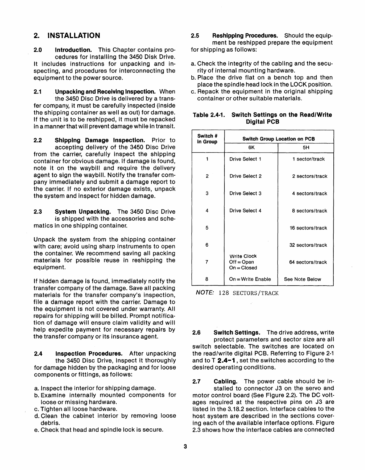
Table
2.4-1.
Switch
Settings
on the Read/Write
Digital PCB
Switch #Switch Group Location on PCB
in
Group 6K
5H
1Drive Select 1 1
sector/track
2Drive Select 22
sectors/track
3Drive Select 34
sectors/track
4Drive Select 48
sectors/track
5
16
sectors/track
6
32
sectors/track
Write
Clock
7
Off=Open
64
sectors/track
On =Closed
8On =Write Enable See Note Below
NOTE:
128
SECTORS
/TRACK
2.6
Switch
Settings. The drive address,
write
protect parameters and
sector
size are all
switch
selectable. The
switches
are located on
the read/write
digital
PCB. Referring
to
Figure
2-1
and
to
T
2.4-1
,set the
switches
according
to
the
desired operating conditions.
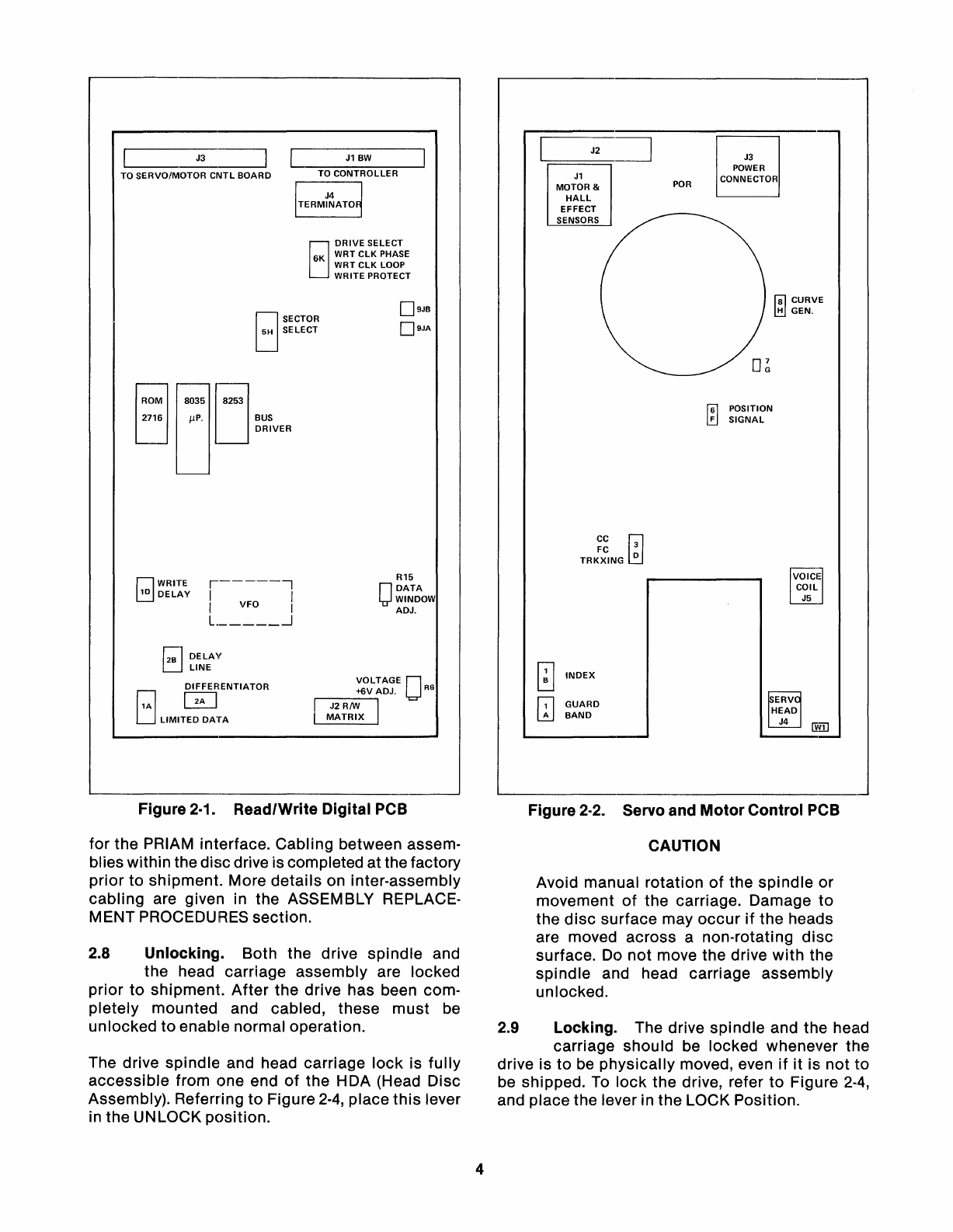
2.7 Cabling. The power cable should
be
in-
stalled
to
connector
J3 on the servo and
motor
control board (See Figure
2.2).
The
DC
volt-
ages required at the respective pins on J3 are
listed in the 3.18.2 section. Interface cables
to
the
host
system are described in the
sections
cover-
ing each
of
the available interface options. Figure
2.3 shows how the interface cables are connected
oSECTOR
oSELECT
____
J3_~
TO
SERVO/MOTOR
CNTL
BOARD
tj
0M
lJ035
J253
2716 IlP. BUS
DRIVER
J1
BW
TO
CONTROLLER
EJ
DRIVE
SELECT
6K
WRT
CLK
PHASE
•WRT
CLK
LOOP
WRITE PROTECT
D9JB
D9JA
J2
~
"-;:===~
J1
MOTOR &
HALL
EFFECT
SENSORS
POR
J3
POWER
CONNECTOR
f8l
CURVE
l!!1
GEN.
f61
FPOSITION
~
SIGNAL
rJWRITE
~DELAY
r------,
I
VFO
I
II
L
..J
R15
O
DATA
WINDOW
ADJ.
CC
W
FC
3
TRKXING
0
VOICIJ
=
COIL
J5
GUARD
BAND
r;;l
DELAY
L:J
LINE
o
0ENTIATOR
LJ
LIMITED
DATA
Figure 2·1. Read/Write
Digital
PCB
for the PRIAM interface. Cabling between assem·
blies within the discdrive is completed at the factory
prior
to
shipment. More
details
on inter-assembly
cabling
are given in the ASSEMBLY REPLACE-
MENT PROCEDURES section.
2.8 Unlocking. Both the drive
spindle
and
the head carriage assembly are locked
prior
to
shipment.
After
the drive has been com·
pletely
mounted and cabled, these
must
be
unlocked
to
enable normal operation.
The drive spindle and head carriage
lock
is
fully
accessible
from one end
of
the HDA (Head Disc
Assembly). Referring
to
Figure 2·4, place
this
lever
in the UNLOCK
position.
4
o
INDEX
IT]
Figure 2·2. Servo and
Motor
Control PCB
CAUTION
Avoid manual rotation
of
the
spindle
or
movement
of
the carriage. Damage
to
the
disc
surface may
occur
if
the heads
are moved across anon-rotating
disc
surface. Do
not
move the drive
with
the
spindle
and head carriage assembly
unlocked.
2.9 Locking. The drive
spindle
and the head
carriage shou
Id
be locked whenever the
drive is
to
be
physically
moved, even
if
it
is
not
to
be shipped.
To
lock
the drive, refer
to
Figure
2-4,
and place the lever in the LOCK Position.
•
~
........
.........
........
",
TO SPECIAL CONN.
ON FIRST
DRIVE
PN
NO. 922576-50-1
................
................ ................
........
........
........
TOJ1
SECOND
DRIVE
,
........
........
........
........
........
'...--
PART NO. 922576-50-1
PLUGS
INTO
J1
CONN.
ON
DRIVE
TOP
PCB
•
FROM
CONTROLLER
BOTH CABLES PLUG
INTO
PN
NO. 922576-50-1
CONNECTOR
*
MAY
BE
DUPLICATED
FOR
UP
TO 3
DRIVES
Figure
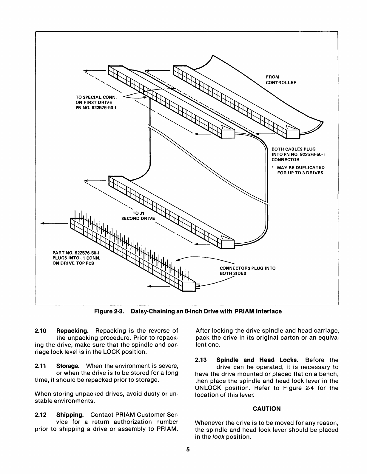
2-3.
Daisy-Chaining an a-inch Drive
with
PRIAM
Interface
2.10 Repacking. Repacking is the reverse
of
the
unpacking
procedure. Prior
to
repack-
ing the drive, make sure
that
the
spindle
and car-
riage
lock
level is in the LOCK
position.
2.11
Storage. When the environment is severe,
or
when
the
drive is
to
be stored
for
along
time,
it
should be repacked
prior
to
storage.
When
storing
unpacked drives, avoid
dusty
or
un-
stable
environments.
2.12 Shipping.
Contact
PRIAM
Customer
Ser-
vice
for
areturn
authorization
number
prior
to
shipping
adrive
or
assembly
to
PRIAM.
5
After
locking
the drive
spindle
and head carriage,
pack
the drive in
its
original
carton
or
an equiva-
lent one.
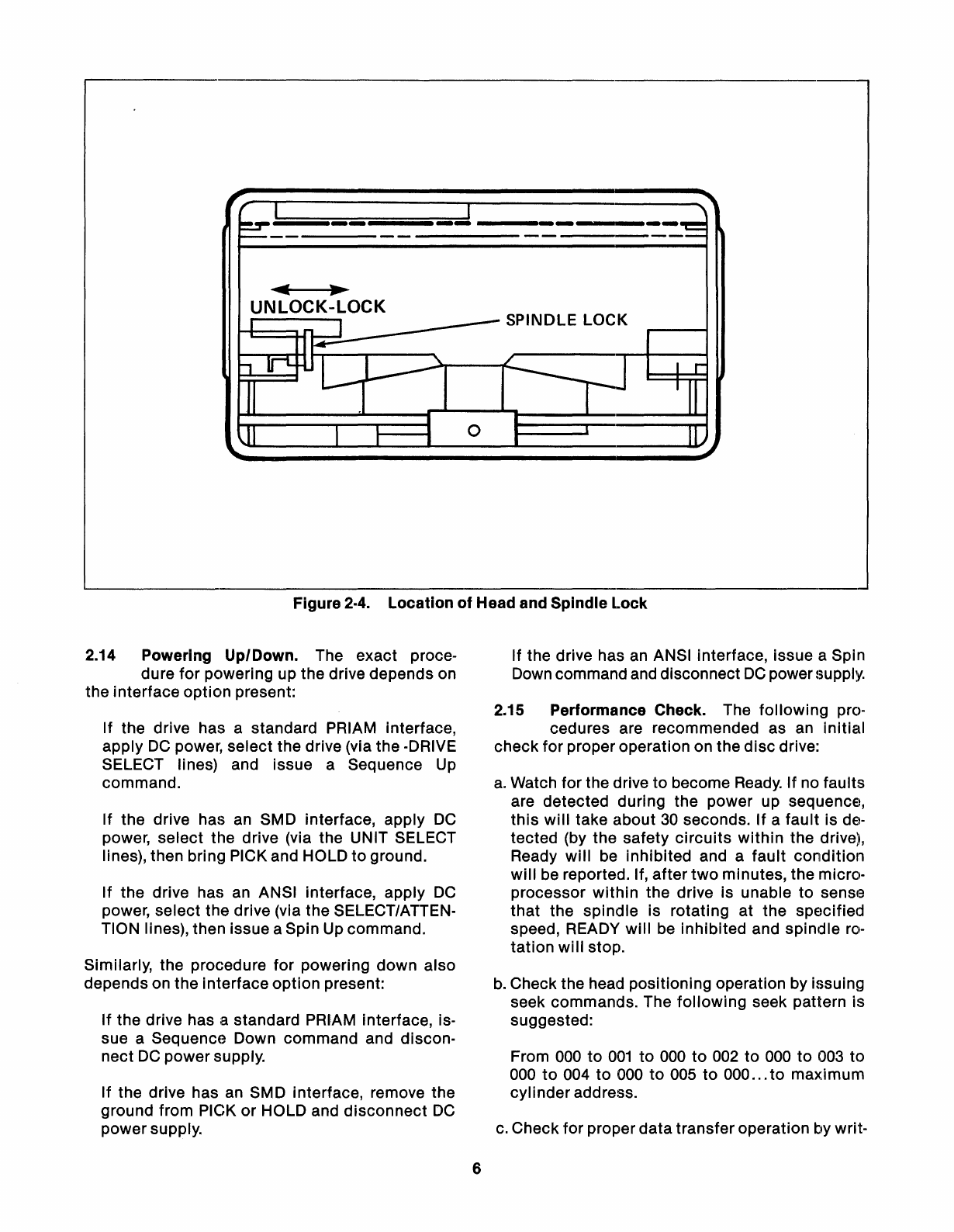
2.13
Spindle
and Head Locks. Before the
drive can be operated,
it
is necessary
to
have the drive mounted
or
placed
flat
on abench,
then place the
spindle
and head
lock
lever in the
UN
LOCK
position.
Refer
to
Figure
2-4
for
the
location
of
this
lever.
CAUTION
Whenever the drive is
to
be moved
for
any reason,
the
spindle
and head
lock
lever should be placed
in the
lock
position.
;iiiiiiiiiiiiiiiii';_iiiiiiHi
iiiiiiiiiiiiiiiiiiiiiiiiiii_iiiiiiii_=
_
SPINDLE LOCK
o
Figure 2·4.
Location
of
Head and Spindle
Lock
2.14 Powering Up/Down. The
exact
proce-
dure
for
powering up the drive depends on
the
interface
option
present:
If the drive has astandard PRIAM interface,
apply
DC
power,
select
the drive (via the -DRIVE
SELECT lines) and issue aSequence Up
command.
If the drive has an SMD interface, apply
DC
power,
select
the drive (via the UNIT SELECT
lines), then bring PICK and HOLD
to
ground.
If
the drive has an ANSI interface,
apply
DC
power,
select
the drive (via the SELECT/ATTEN-
TION lines), then issue aSpin Up command.
Similarly, the procedure
for
powering
down
also
depends on the interface
option
present:
If
the drive has astandard PRIAM interface, is-
sue aSequence Down
command
and discon-
nect
DC
power
supply.
If the drive has an SMD interface, remove the
ground from PICK
or
HOLD and
disconnect
DC
powersupply.
6
If the drive has an ANSI interface, issue aSpin
Down command and disconnect
DC
powersupply.
2.15 Performance Check. The
following
pro-
cedures are recommended as an
initial
check
for
properoperation on the
disc
drive:
a.
Watch for the drive
to
become Ready.
If
no faults
are detected during the power up sequence,
this
will
take
about
30
seconds.
If
a
fault
is de-
tected
(by the
safety
circuits
within
the drive),
Ready
will
be
inhibited
and a
fault
condition
will
be reported. If,
after
two
minutes, the micro-
processor
within
the drive is unable
to
sense
that
the
spindle
is
rotating
at the
specified
speed, READY
will
be
inhibited
and
spindle
ro-
tation
will
stop.
b.
Check the head positioning operation by issuing
seek commands. The
following
seek pattern
is
suggested:
From 000
to
001
to
000
to
002
to
000
to
003
to
000
to
004
to
000
to
005
to
000
...
to
maximum
cylinder
address.
c.
Check
for
proper
data
transfer
operation by writ-

ing and then reading data with each read/write
head.
CAUTION
Write operations alter previously recorded data
Most
disc
s/ystems require aformatted
disc
be-
fore datatransfer can be performed.
7
A
disc
surface
defect
map is supplied by PRIAM
with
each
disc
drive. The defect map indicates
the location
of
defects
discovered during manu-
facturing and testing. Adefect location is spe-
ci'fied by the number
of
byte
positions
from the
index mark.

NOTES
8

3. FUNCTIONAL DESCRIPTION
3.1
Overvh!w. The PRIAM 3450 Disc Drive
has three discs, with atotal
of
six magnetic
surfaces. Each surface accommodates one head,
as shown in Figure
3-1.
On the
"bottom"
surface,
the head reads the servo information. The remain-
ing heads write and read datasurfaces0through
4.
r---
-
DATAH~
DISC
NO.4
)
DATAH~
NO.3
w
DIHAHE~
t:l
«
DISC
NO.2
~
)«
u
DATAHE~
0
w
NO.1
~
....
:I:
0
Z
g;
DIHAHE~
DISC
NO.O
)
SER\~
HEAD
I-
.....----....
Figure
:~·1.
Servo and Data Surfaces
The PRIAM 7050 has exactly the same configura-
tion
of
disc
surfaces and heads as the
3450,
but
it
achieves
twice
the storage capacity by having
twice
as many data tracks per inch.
3.2
Servo Surface. The purpose
of
the servo
surface is
to
provide acoordinate system
by which the electrical
circuitry
of
the
disc
drive
can locate spe'cific areas for writing or reading data.
The servo surface is written once at the factory,
and thereafter is aread-only area. The information
on the servo surface determines the angular posi-
tion
of
the disc, as well as the radial position
of
the head carriage.
The servo surface is divided into four
distinct
groups
of
tracks. From the inside (hub) out, these
are as follows:
a.
Guardband 2(landing zone)
b.
Guardband 1
c.
Servo Data Band
d.
Guardband 1
Within each
of
these bands, ,there are four types
of
tracks-odd normal tracks, odd quadrature
tracks, even normal tracks, and even quadrature
tracks. Each track type produces acharacteristic
signal at the servo read head, as described below
in the SERVO
PATTERN
section. The closer the
servo read head is
to
aparticulartrack, the greater
9
will
be
that track's contribution
to
the servo
head's output.
The servo
circuitry
compares the amplitudes
of
the signals from adjacent tracks, and identifies an
equal-ampliture
condition
as a
"track
crossing."
During seek operations, the
servo
circuitry
counts
the track crossing in order
to
stop at the cylinder
address requested by the controller. During write
and read operations, the servo
circuitry
adjusts
the position
of
the head carriage in such amanner
as
to
preserve the equal-amplitude condition,
thus keeping the write/read head
"on
track."
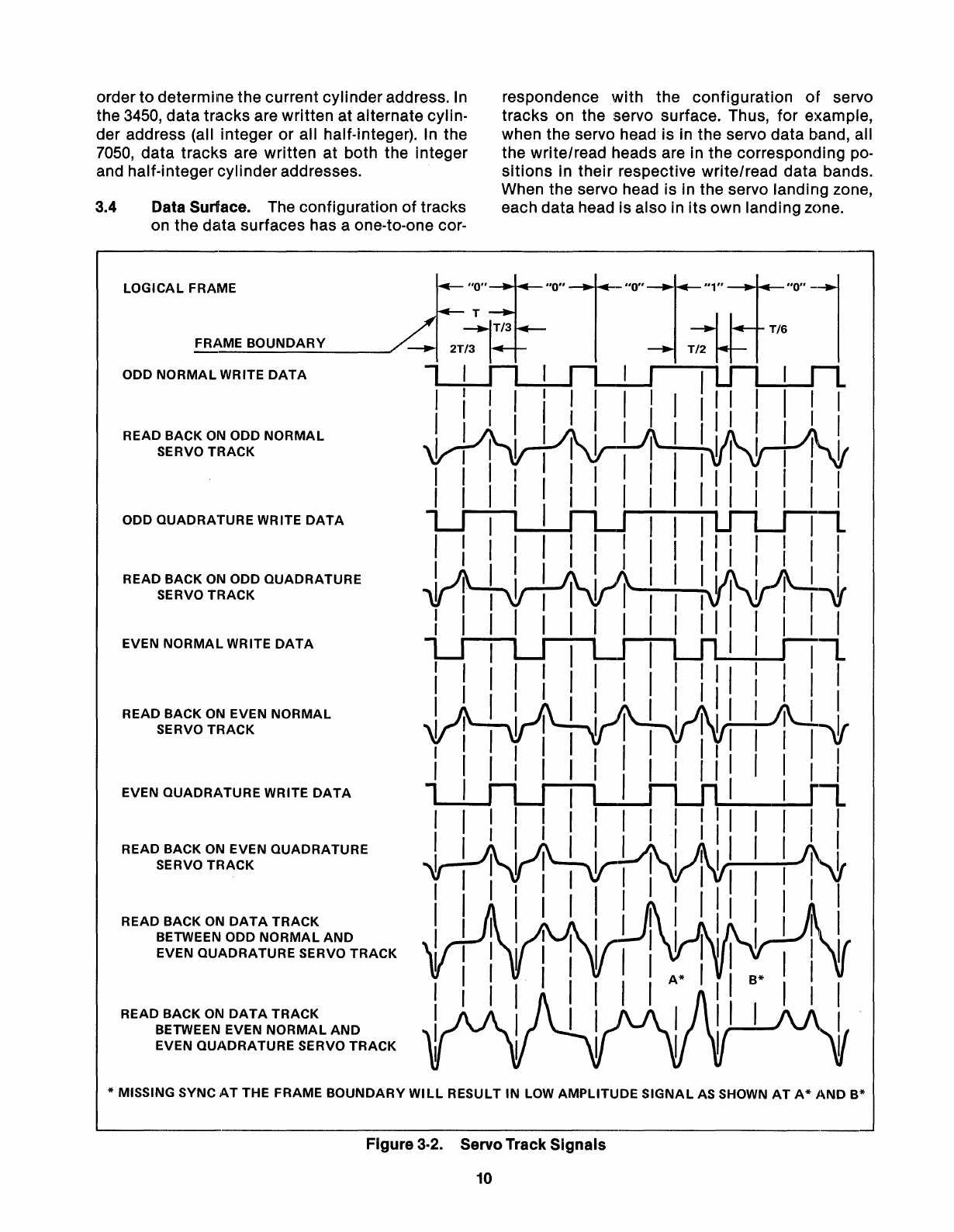
3.3
Servo Pattern. Figure
3-2
shows the four
kinds
of
servo track signals. The normal
servo data patterns are written on the integer
tracks, and the quadrature servo data patterns are
written on the half-integer tracks.
The negative pulses are sync pulses.
In
the all
"0"
pattern, these pulses
occur
at regular intervals,
and serve to define the frame boundaries. When
the servo head reads a
"1,"
an
additional negative
pulse occurs in the mid-frame position. The frame
time interval
(T)
is equal
to
16
write/read data
bit
times. Most
of
agiven track is written
with
the
"0"
pattern. The
"1"
pattern occurs once each revolu-
tion
of
the disc, and serves
to
define the INDEX
location.
The positive pulses are used by the servo
circuitry
to
recognize track crossings or
to
maintain the on·
track condition. Referring again
to
the all
"0"
pattern,
it
can be seen that the even normal track
generates positive pulses occurring one-third
of
the way across the frame, while the odd normal
track generates positive pulses occurring at the
two-thirds point. The quadrature track patterns
have positive pulses alternately at the one-third
and two-thirds positions.
When the servo read head is midway between
two
adjacent tracks
(a
"track-crossing"
position) the
output
resembles the patterns shown at the
bottom
of
Figure
3-5.
Successive frames
produce the equal-amplitude positive peaks,
alternating
with
single large peaks. By analyzing
which frames have the equal-amplitude peaks,
and whether the large peaks
occur
at the one-third
or the two-thirds locations
within
the frame, the
servo
circuitry
is able
to
determine which
of
the
four kinds
of
"track-crossing"
positions is being
indicated. Note that the servo read head is mid-
way between
two
adjacent tracks when the data
write/read heads are
"on-track."
The servo
circuitry
counts the track crossing in
order
to
determine the current cylinderaddress.
In
the 3450, data tracks are written at alternate cylin-
der address (all integer or all half-integer).
In
the
7050,
data tracks are written at both the integer
and half-integer cylinder addresses.
3.4 Data Surface. The configuration
of
tracks
on the data surfaces has aone-to-one cor-
LOGICAL
FRAME
FRAME
BOUNDARY
ODD
NORMAL
WRITE
DATA
READ BACK
ON
ODD
NORMAL
SERVO
TRACK
ODD
QUADRATURE
WRITE
DATA
READ BACK
ON
ODD
QUADRATURE
SERVO
TRACK
EVEN
NORMAL
WRITE
DATA
READ BACK ON EVEN
NORMAL
SERVO
TRACK
EVEN
QUADRATURE
WRITE
DATA
READ BACK
ON
EVEN
QUADRATURE
SERVO
TRACK
READ
BACK
ON
DATA
TRACK
BETWEEN ODD
NORMAL
AND
EVEN
QUADRATURE
SERVO
TRACK
READ
BACK
ON
DATA
TRACK
BETWEEN EVEN
NORMAL
AND
EVEN
QUADRATURE
SERVO
TRACK
respondence with the configuration
of
servo
tracks on the servo surface. Thus, for example,
when the servo head is in the servo data band, all
the write/read heads are in the corresponding po-
sitions
in their respective write/read data bands.
When the servo head is in the servo landing zone,
each data head is also in
its
own landing zone.
*MISSING SYNC
AT
THE FRAME
BOUNDARY
WILL
RESULT
IN
LOW
AMPLITUDE
SIGNAL
AS SHOWN
AT
A*
AND
B*
Figure 3·2. Servo Track Signals
10

The
format
for
the
Ski·p
Defect Record is as
follows:
The write/read
data
tracks
are numbered consec-
utively,
starting
with
track
0nearest the
outside
edge
of
the disc. Each write/read
data
track
is di-
vided
into
sectors. The division
of
tracks
into
sec-
tors can be adjusted by the user through
switch
settings
on
the
read/write
digital
PCB, as detailed
in the INSTALLATION section.
3.5 Track Format. In a
typical
track
format,
each
track
isdivided as
follows:
Data sync (FB hex)
1
st
defect
location
2nd
defect
location
3rd
defect
location
Checksum
Fill characters (zeros)
1byte
2bytes
2bytes
2bytes
2bytes
2bytes
Index Mark
Gap (type
1)
SkiPDefect Record
N
Identical
Data Sectors
Gap (type
3)
The index mark is a1.92
microsecond
(tWO-byte
times) pulse, derived from the index pattern on the
servo
data
surface.
The type 1gap
allows
for
VFO synchronization
for
data
separation. It
consists
of
zeros, and has a
minimum
length
of
23
bytes.
3.7 Data
Sector
Format. The N
identical
Data Sectors have the
following
structure:
Sector
Mark
Gap (type
1)-zeros
(23
bytes
minimum)
Address Field
Gap
(type2)-zeros
(11
bytes
minimum)
Data Field
The
sector
mark
is
a960 nanosecond (one byte
time) pulse
which
occurs
at
the beginning
of
each
sector. It is generated by
the
servo circuitry, using
abyte
clock
which
is
initialized
by the index
pulse.
The
format
for
the Address Field is as
follows:
The Data Field has the
following
structure:
The
composition
of
the Skip Defect Record and
of
the
N
identical
DataSectors are described below.
The type 3gap is a
function
of
sector
size, and is
used
to
fill
(with zeros) the space
left
over
after
the
largest
possible
integer
number
of
sectors
(com-
mensurate
with
the
switch
settings) have been
written.
It should always
be
remembered that the switch set-
tings determining sector size are read by the micro-
processor as part
of
the Sequence Up process.
Thus, achange in these switch settings will not take
effect
until
the drive is once again sequenced up,
or
re-initialized from apower
down
condition.
Sync pattern (F9 hex)
Head and high order
cylinder
address
Low order
cylinder
address
Sector
address
Sector
length and flag
CRC
Fi
II
characters (zeros)
Sync pattern (FD hex)
Data bytes (according
to
sector
length)
CRC
Fill characters (zeros)
1byte
1byte
1byte
1byte
1byte
2bytes
2bytes
1byte
2bytes
2bytes
3.6 Defect
Location
Record Format. The
De-
fect
Record (PRIAM
interface
only) can
identify
up
to
three
defective
sectors
on the track.
The
following
diagram summarizes
the
typical
track
format:
DATA GAP GAP SKIP GAP ADDRESS GAP DATA GAP ADDRESS GAP DATA
FIELD TYPE TYPE DEFECT TYPE FIELD TYPE FIELD TYPE FIELD TYPE FIELD
N 3 1RECORD 1 1 2 1 1 2 22
t
INDEX
MARK
t
SECTOR
MARK
1
11
t
SECTOR
MARK
2

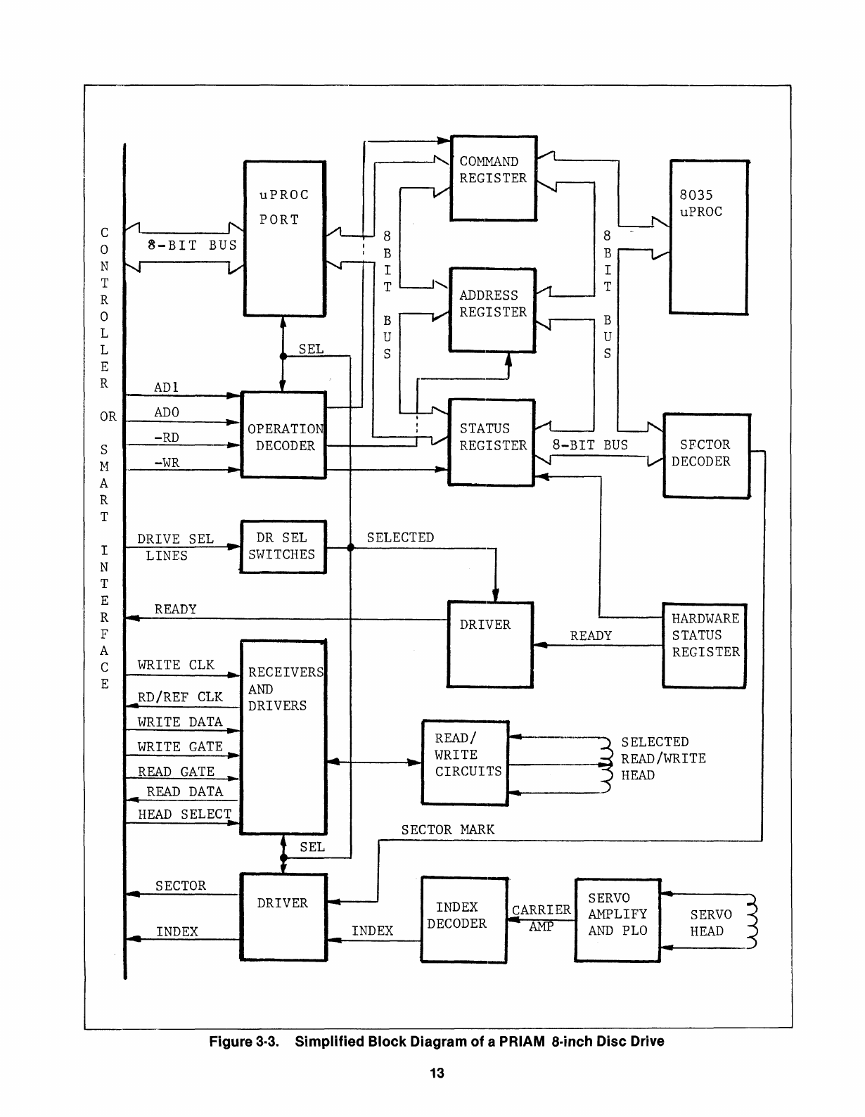
3.8
Overview. Figure
3-3
is asimplified
block
diagram
of
aPRIAM 8-inch
disc
drive with
the standard PRIAM interface. The overall organi-
zation shown is the same for all drives in the
8"
family. However, the names
of
the
specific
inter-
face signals vary as afunction
of
the interface
option present.
The
disc
drive has its own
(8035)
microprocessor,
which controls the sequencing
of
all the opera-
tions
that
occur
in the drive.
3.9
Drive Selection. The
disc
drive must
be
properly selected before
it
wi
II
respond
to
any
of
the signals on the controller interface. On
the standard PRIAM interface, this is accomplished
by placing the proper address on
t11e
DRIVE
SELECT
1-4
lines.
On
the SMD interface, the
proper address is placed on the UNIT SELECT
1,
2,
4and 8lines and the UNIT SELECT
TAG
line is ac-
tivated.
In
general, the interface lines
to
be used
may
be
determined by referring
to
the section
(below) describing the
specific
interface involved.
The address
of
an
individual drive is determined
by
switch
settings on the read/write digital
PCB,
as discussed in the INSTALLATION section. The
drive responds
to
the selection procedure only
when
its
switch-selected address matches that
placed on the interface by the controller.
3.10 Power Up/Down Sequences. When power
is applied, the Microprocessor Initialization
sequence occurs automatically. The microproces-
sor then goes
into
the idle state, in which
it
moni-
tors the controller interface for acommand.
The controller may then issue aSequence
Up
command
to
the drive (the exact manner in which
this
is done depends on the interface option
present). The microprocessor recognizes
this
command and starts the spindle motor. When the
motor
is running at the proper speed, the micro-
processor reads the sector length switches, and
configures the drive
to
operate in terms
of
the
chosen sector length. Next
it
calls the
RSTRGO
subroutine, which moves the heads
to
cylinder
zero. It then enables the drive ready status, resets
the busy condition, and returns
to
the idle state.
The drive is'stopped by issuing aSequence Down
command. This causes the heads
to
return
to
the
landing zone, and stops the spindle motor.
3.11
MotorControl Circuitry. The spindle motor
is abrushless (electronic commutating)
permanent magnet
DC
motor. The speed
of
the
12
motor
is controlled by aclosed-loop
circuit
con-
taining Hall
effect
sensors and acomparator.
Figure
3-4
is a
block
diagram
of
the motor control
circuitry. The microprocessor sets the OFF signal
true
to
inhibit
spindle rotation, or false
to
allow
spindle rotation. The microprocessor monitors
the speed
of
spindle rotation. If, during the power
up sequence, the
motor
does not reach
its
speci-
fied speed
within
one minute, or if, during normal
operation, the
motor
speed passes outsicJe the
specified speed range, the microprocessor
will
set the Fault condition, restore the heads
to
the
landing zone, and
inhibit
the spindle rotation.
3.12 Seek Modes. The servo system has
two
main
mocJes
of operation -
On
Track mode
(also called Position mode) and Move mode.
Move mode becomes active when the drive is
commanded
to
move the heads. The microplroces-
sor receives the new target cylinder address and
the seek command, determines the direction
of
travel and the number
of
tracks
to
be
crossed, and
sets Move mode.
When the servo is in Move mode, avelocity profile
(produced by adigital-to-analog converter) is com-
pared (via asumming junction) with the
output
of
an electronic tachometer, which indicates the
ve-
locity
of
headmotion. The difference signal from
the summing
junction
is fed
to
the servo power
amplifiers, which control the voice coil motion.
The heads are driven toward the new cylinder
address. The servo
circuitry
monitors the track
crossings and decreases the velocity
of
head
motion as the selected cylinder is
approachE~d.
When the heads are
within
100
microinches
of
the
new cylinder, the On Track mode becomes active.
In
the On Track mode, the heads are held precisely
over the designated track. Any unintended head
movement is detected by the electronic tachom-
eter and fed
to
the summing junction. This in turn
causes the servo power amplifiers
to
adjust the
head position, so that the heads remain at the
desired location.
Servo safety
circuits
drive the heads
to
the land-
ing zone upon detection
of
alow power condition,
or
if
both Move and
On
Track modes
occur
simul-
taneously. The safety
circuits
also
monitor
the
voice coil speed. If the specified speed is ex-
ceeded,
or
if
the continuous position information
is lost, an Overspeed signal is established and the
servo power amplifiers are disabled. Seek Fault is
set
if
any
of
the above
conditions
develop.
C
o
N
T
R
o
L
L
E
R
OR
S
M
A
R
T
--
~
COMMAND
/l
REGISTER
~
uPROC r----v 8035
PORT
L-f'..
uPROC
V1
'"
VL-.- 88-
B-BIT
BUS
IB
r---v-
IB
........,-
V
N--
I I
T
L-J
........
ADDRESS
.....-1
T
--V
REGISTER
BNB
UU
SEL
SS
ADI
ILL
-
ADO
--i
-
OPERATION
,
STATUS
A
--.1'.;
-RD
;V
DECODER
REGISTER
8-BIT
BUS
SFCTOR
--
-WR
-
"'i
V
DECODER
-
"'
SECTOR
MARK
SELECTED
I
N
T
E
R
F
A
C
E
DRIVE
SEL
_
DR
SEL
LINES
..
SWITCHES
READY
-
WRITE
CLK
~
RECEIVERS
AND
_RD/REF
CLK
DRIVERS
WRITE
DATA
WRITE
GATE_
READ
GATE
_
_
READ
DATA
HEAD
SELECI
SEL
-
..
DRIVER
READ/
WRITE
CIRCUITS
~----~
HARDWARE
_
READY
STATUS
~------~--~
REGISTER
SECTOR
...
_
INDEX
DRIVER
INDEX
INDEX
DECODER
SERVO
~ARRIER
AMPLIFY
AMP
AND
PLO
-
~
SERVO
~
HEAD
"')
-<
Figure 3·3. Simplified Block Diagram of aPRIAM a·inch Disc Drive
13
(3) SOURCES
CURRENT FEEDBACK
J2
hRED
r-;l
Ioo-.-------
...
~J.-+-l-----:....:.:;;.;;;;....--......-.:i:........a.-
BLACK
8ITO
MOTOR
-
-
TO
R/W
/-LP
TO
HALl.
EFFECT
SWITCHES
~I
I·
'V'
L_.J
J1
r-'
+5V
I5I •
II
I1I
J2
r-"
@SPD
!34 I
CURRENT
1-----1
SOURCE
1---4
DRIVER
8748
J1
r--,
I4I
S1
FROM ON/OFF
RIW
>----
..
/-LP
HALL
I!
EFFECT I3 ,
S2
POSITION I2
,I
53
ENCODER
t------0I-------.I
I I
L_.J
r--+
2F
CURRENT
1-----1
SINK
r---""-
DRIVER
D/A
-MPOR
J2
L.::£!CP~O~R
--11---'
-CPOR
r-l
-PORD
POWER
~--A-PO-R~!~-~I-
RESET
ON
II
PLO SAFE RESET
r--l
L_...J
L..------I'
I
TO
R/W
PCB
Figure
3-4.
Motor
Controller
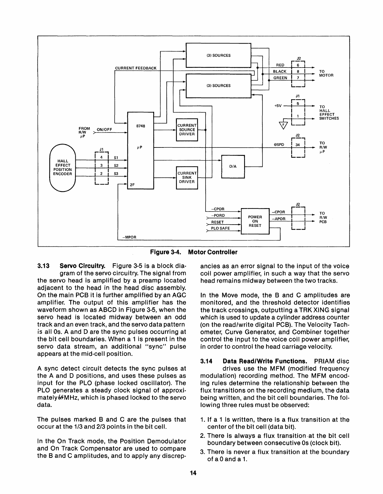
3.13 Servo Circuitry. Figure
3-5
is ablock dia-
gram
of
the servo circuitry. The signal from
the servo head is amplified by apreamp located
adjacent
to
the head in the head
disc
assembly.
On
the main PCB
it
is further amplified by
an
AGC
amplifier. The
output
of
this
amplifier
has the
waveform shown as ABCD in Figure
3-5,
when the
servo head is located midway between
an
odd
track and an even track, and the servo datapattern
is aliOs. Aand Dare the sync pUlses occurring at
the
bit
cell boundaries. When
a1
is present in the
servo data stream, an additional
"sync"
pulse
appears at the mid-cell position.
Async detect
circuit
detects the sync pulses at
the Aand Dpositions, and uses these pulses as
input for the
PLO
(phase locked oscillator). The
PLO
generates asteady
clock
signal
of
approxi-
mately69-MHz, which is phased locked
to
the servo
data.
ancies as an error signal
to
the input
of
the voice
coil power amplifier, in such away that the servo
head remains midwaybetween the
two
tracks.
In
the Move mode, the
Band
Camplitudes are
monitored, and the threshold
detector
identifies
the track crossings,
outputting
aTRK XING signal
which is used to update acylinder address Gounter
(on the read/write digital
PCB).
The Velocity Tach-
ometer, Curve Generator, and Combiner together
control the
input
to
the voice coil power amplifier,
in order
to
control the head carriage velocity.
3.14 Data Read/Write Functions. PRIAM
disc
drives use the MFM (modified frequency
modulation) recording method. The MFM encod-
ing rules determine the relationship between the
flux transitions on the recording medium, the data
being written, and the
bit
cell boundaries. The fol-
lowing three rules must
be
observed:
The pulses marked
Band
Care the pulses that
occur
at the 1/3 and
2/3
points in the
bit
cell.
In
the On Track mode, the Position Demodulator
and
On
Track Compensator are used
to
compare
the
Band
Camplitudes, and
to
apply any discrep-
1.
If
a 1 Is written, there is aflux transition at the
center
of
the
bit
cell (data bit).
2.
There is always aflux transition-at the
bit
cell
boundary between consecutive
Os
(clock bit).
3.
There is never aflux transition at the boundary
of
a0 and a
1.
14
This manual suits for next models
1
Table of contents
Other PRIAM Storage manuals

Popular Storage manuals by other brands

Seagate
Seagate STD224000N - DAT Scorpion 24 Tape Drive installation manual

Kingston Technology
Kingston Technology Wi-Drive user guide

ECOSAFE
ECOSAFE ASDM22 instruction manual

Huawei
Huawei OceanStor S2600 manual

IBM
IBM StorVize V7000 Gen2 Quick installation guide

Huawei
Huawei OceanStor Dorado V3 Series Parts Replacement


Sparehand Systems
Sparehand Systems TF-408 quick start guide

IBM
IBM DATA MIGRATION SERVICES - brochure

Seagate
Seagate ST3146707LW - Cheetah 146 GB Hard Drive datasheet

Samsung
Samsung MZ-5PA064 user manual

Silicon Graphics
Silicon Graphics TP9400 RAID owner's guide

Apricorn
Apricorn Aegis Padlock A25-PLE256 256GB quick start guide