Pribusin ITC-79-FTF Series User manual
Manufacturers of Process
Controls and Instrumentation
Instruction Manual
Model:
Serial #:
Installed
24 VDC, 160 mA
Not Installed
Relay:
Function: Frequency to Frequency Isolator
Option:
ITC-79-FTF
Power:
(If special or required)
-BUF (Frequency/Pulse Buffer)
Response Time: 100 microsec.
-DIV (Frequency Divider)
Input: 0-10 VDC
Thresholds: ON: TP1=3V OFF: TP2=1V
ON: TP1= OFF: TP2=
For Technical Assistance And Questions Call
USA: (734) 677-0459 CANADA: (905) 660-5336

Restocking Policy
Page v
Warranty Policy
All product returned to Pribusin Inc. in prime condition (not
damaged, scratched or defaced in any way) within seven (7)
months from the original date of shipment is subject to a 50%
restocking charge. All product must be accompanied by a
Return Authorization number (RA number) which must be
obtained from Pribusin Inc. prior to returning any product.
After seven (7) months from the original date of shipment,
products cannot be returned for restocking.
Custom designed products, modified products or all non-
standard products may not be returned for restocking.
Pribusin Inc. warrants equipment of its own manufacture to be
free from defects in material and workmanship, under normal
conditions of use and service, and will replace any component
found to be defective, on its return to Pribusin Inc.,
transportation charges prepaid, within one year of its original
purchase. Pribusin Inc. will extend the same warranty
protection on equipment, peripherals and accessories which is
extended to Pribusin Inc. by the original manufacturer. Pribusin
Inc. also assumes noliability, expressed or implied, beyond its
obligation to prelace any component involved. Such warranty
is in lieu of all other warranties, expressed or implied.

Function:
The ITC-79-FTF is a Frequency to Frequency Isolator
that is easily field configurable to one of many input
types such as several voltages or dry contact. Three
standard outputs are available (TTL, 24 VDC, and Dry
Contact) which can be used individually or
simultaneously. Discrete ON and OFF threshold
adjustments allow for easy & accurate input signal
conditioning. Adjustable response times allow for
appropriate signal filtering.
The ITC-79-FTF-BUF is similar to the -FTF but has a
microprocesser that can store incoming pulses in a
buffer and release them slowly to a slower counting
device.
The ITC-79-FTF-DIV is another variation of the -FTF
and has the capability to divide the incoming frequency
by any number between 1 and 65535.
Calibration:
The ITC-79-FTF has individual ON and OFF threshold
adjustment using multiturn potentiometers. All
potentiometers have a test point where a voltage of -10
to +10 VDC indicates the threshold level as -100% to
+100%. This allows for easy field calibration with the
instrument running.
Standard Features:
DIN-Rail Mount (small size)
High Input-Output-Power Isolation (800VAC Test)
Wide Input Frequency Range (from 0 Hz to 10 KHz)
Many Input Types & Ranges (Voltage, Dry Contact)
3 Standard Outputs (TTL, 24V, Dry Contact)
Optional Buffer or Divider Function
Adjustable Response Time for Noise Rejection
Easy Field Calibration (Typ. calibration time < 2 min.
using handheld meter only)
Microprocessor Controlled for High Accuracy
24 VDC Supply for Dry Contact Input
Power: 24 VDC
CSA and NRTL Approval Pending
Specifications:
Isolation: Input to Output to Power 800 VAC (test)
Operating Temperature: -40 Deg.C. to +50 Deg.C.
Temperature Effects: +/-0.5% max., 0.2% typ.
(for 40 Deg.C. change)
Contact Rating: 0.4A @ 125VAC
2A @ 30VDC
Page B4
Model: ITC-79-FTF
Frequency To Frequency Isolator
NRTL/C
R
Manufacturers of Process
Controls and Instrumentation

Page B4
ITC-79-FTF
Available Models:
ITC-79-FTF: Frequency Isolator
Outputs: TTL, 24VDC, Dry Contact
ITC-79-FTF-DIV: Frequency Isolator with Divider
Outputs: TTL, 24VDC, Dry Contact
Function: Divide Input by Division Factor
ITC-79-FTF-BUF: Frequency Isolator with Buffer
Outputs: TTL, 24VDC, Dry Contact
Function: Store Pulses & Release Slowly
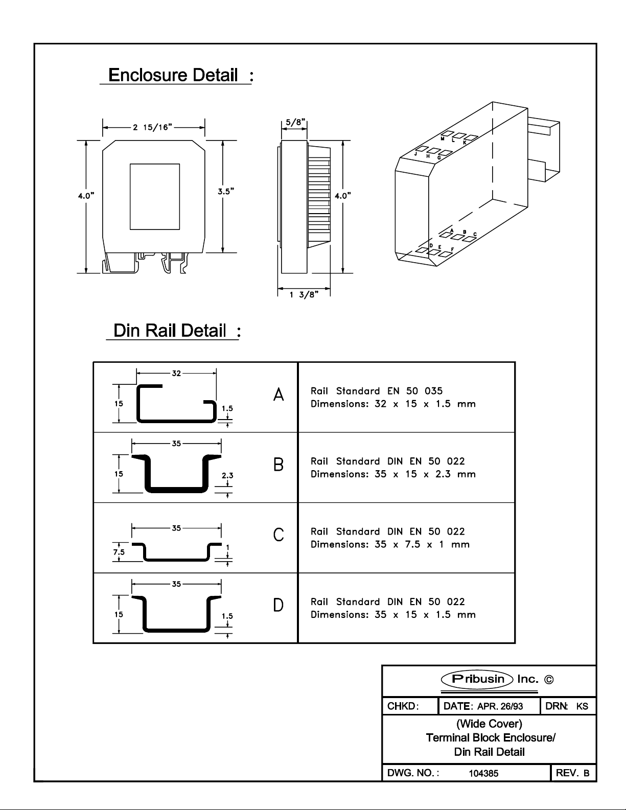
Dimensions: Calibration:
Calibration is made easy by multi
turn potentiometers with test
jacks for meter connection.
Connection:
Manufactured By:
www.pribusin.com
CANADA:
Pribusin Inc.
101 Freshway Dr. Unit 57
Concord, Ontario, L4K 1R9
Ph: (905) 660-5336
Fx: (905) 660-4068
USA:
Pribusin Inc.
743 Marquette Ave
Muskegon, MI 49442
Ph: (231) 788-2900
Fx: (231) 788-2929
Subject to change without notice


Dwg. 105133 Page 1
Calibration & Setup Procedure for ITC-79-FTF
(includes ITC-79-FTF-BUF & ITC-79-FTF-DIV)
1. Factory Settings: (unless otherwise specified at time of order)
ITC-79-FTF:
Input Type: Voltage Input, TTL level (0-5 VDC) (jumper H2-8 inserted)
Thresholds: ON: TP1 = 3V , OFF: TP2 = 1V
Relay & 24V Pulse: Follows input directly (jumper H4-1 installed)
Response Time: 100 microsec. (jumper H2-2 installed)
TTL Output: Follows input directly (jumper H4-4 installed)
ITC-79-FTF-BUF:
Input Type: Voltage Input, TTL level (0-5 VDC) (jumper H2-8 inserted)
Thresholds: ON: TP1 = 3V , OFF: TP2 = 1V
Relay & 24V Pulse: Buffered pulse output (jumper H4-2 installed)
Response Time: 100 microsec. (jumper H2-2 installed)
TTL Output: Buffered pulse output (jumper H4-5 installed)
Output Pulse Rate: 500 msec.
ITC-79-FTF-DIV:
Input Type: Voltage Input, TTL level (0-5 VDC) (jumper H2-8 inserted)
Thresholds: ON: TP1 = 3V , OFF: TP2 = 1V
Relay & 24V Pulse: Divided Output (jumper H4-2 installed)
Response Time: 100 microsec. (jumper H2-2 installed)
TTL Output: Divided Output (jumper H4-5 installed)
Division Factor: 100
2. Input Type:
Determine the type of input that is to be applied to the ITC-79-FTF (choices are
Voltage, Dry Contact, AC or DC Coupled ). Follow the instructions below depending
on which input type you are using:
Voltage Input:
Several input ranges for various voltage levels can be set up by jumpers H2-5
through H2-8. Select only one range and insert only one jumper for that range.
0-10 mV insert jumper H2-5
0-100 mV insert jumper H2-6
0-1 V insert jumper H2-7
0-10 V insert jumper H2-8
Dry Contact Input:
Insert jumper H3 to select a 10 KOhm input impedance. Insert jumper H2-8 to
select a 0-10 V input range. Set the ON threshold to +10 V (using TP1) and
the OFF threshold to +5 V (using TP2).
AC or DC Coupling:
The ITC-79-FTF is set up for DC Coupling by default. To change the input to
AC Coupling, remove jumper J1 and replace it with a 1 uF capacitor.
3. Input Response Time:
There are four response times to choose from for the input conditioning circuitry.
These response times help eliminate noise on the input signal. Choose a response
time that is adequate for your particular frequency input. Make sure that the
highest frequency that is to be accepted by the input has a period greater than the
chosen response time.
10 msec insert jumper H2-4

Dwg. 105133 Page 2
1 msec insert jumper H2-3
100 microsec insert jumper H2-2
10 microsec insert jumper H2-1
For Example, if the maximum frequency is 2000 Hz, the period is 1/2000 sec. or 500
micro seconds. Choose either 100 micro seconds or 10 micro seconds. If you were to
choose 1 msec or 10 msec, the input could not respond fast enough to your highest
input frequency and the ITC-79-FTF would not accept the input.
4. ON & OFF Thresholds:
The ITC-79-FTF has two threshold settings: one for the ON level (rising edge of the
input) and one for the OFF level (falling edge of the input). These threshold
levels must be set such that the amplitude of the input signal is larger than that
of the ON and OFF threshold levels. The ON and OFF LED's indicate which portion of
the pulse is currently being received (on frequencies above 30 Hz, both LED's appear
to be on simultaneously).
In the above example, the input signal swings from -10V to + 10V. A good threshold
level is at -8V and +8V to eliminate any possible ringing noise at the rising and
falling edges. For a dry contact input, choose an OFF Threshold above 0V, say 10-
20% of the full scale signal.
To set the Threshold levels, use a voltmeter between TP1 and TPCOM for the ON
Threshold and adjust the multiturn potentiometer until the meter reads the desired
level. Do the same for the OFF Threshold using TP2 and TPCOM.
Note: If you are using an input range other than 10 V, the Threshold levels of
+/- 10V represent -100% to +100% of the selected input range. For example, a
threshold of 8V represents 80 mV on a 100mV input range setting.

Dwg. 105133 Page 3
5. Output Type:
The ITC-79-FTF has three standard output types. These are Dry Contact, TTL (5V),
and 24 VDC. To activate the TTL output, jumper H4-4 must be inserted (factory
default setting). To activate the relay and 24 VDC output, jumper H4-1 must be
inserted. All outputs can be used simultaneously.
The 24 VDC output is a 'straight through' output which means that it follows the
incoming signal directly (i.e. when the input goes high the 24 VDC output goes high,
etc.). The TTL output is inverted ! (i.e. when the input goes high, the TTL output
goes low and vice versa).
6. Additional Setup & Calibration for ITC-79-FTF-BUF only:
The ITC-79-FTF-BUF stores incoming pulses (frequency) in an internal buffer in its
microprocessor and releases them at a slower rate as a 50% duty cycle square wave.
The output pulse release rate is adjustable from immediate output (no buffering) to
6.5 second pulse durations in 0.1 msec intervals. The pulse release rate is set up
using the jumper strip H1. The release time is encoded in binary which means that
up to 65536 (216) combinations of release rates are selectable. Jumper position H1-
1 is equivalent to 0.1 msec, position H1-2 equals 0.2 msec, H1-3 equals 0.4 msec all
the way to H2-16 which equals 3276.8 msec (3.2768 sec.).
Example: for an output pulse rate of 1/2 second (500 msec.) the jumpers on H1 have
to be as follows.
H1-1 out H1-5 out H1-9 in H1-13 in
H1-2 out H1-6 out H1-10 in H1-14 out
H1-3 out H1-7 out H1-11 out H1-15 out
H1-4 out H1-8 in H1-12 out H1-16 out
The jumpers that are inserted carry the binary weights of 0.8+12.8+25.6+51.2+409.6
which when added together, results in 500.0 msec
Output Selection:
The ITC-79-FTF-BUF can be configured as a 'straight through' instrument or a pulse
buffer or a combination of both. Jumpers H4-1,2,3 control the relay output and
jumpers H4-4,5 control the TTL output. The following tables show how the different
jumpers affect the operation of the outputs:
Relay TTL Output
H4-1 Relay & 24 VDC follow input directly H4-4 TTL Output follow
input directly
H4-2 Relay & 24 VDC driven by buffer H4-5 TTL Output driven by
buffer
H4-3 Relay & 24 VDC is same as TTL output
(depending on H4-4,5)

Dwg. 105133 Page 4
7. Additional Setup & Calibration for ITC-79-FTF-DIV only:
The ITC-79-FTF-DIV takes the incoming pulses (frequency) and provides a 50% duty
cycle square wave output that is divided by an adjustable division factor. The
division factor can be in the range of 1 to 65535 and is encoded in binary on the
jumper strip H1. Position H1-1 carries the weight 1, H1-2 equals 2, H1-3 equals 4,
all the way to H1-16 which equals 32768. As division by 0 is invalid, the output
will stop if no division factor is set up on H1.
Example: to divide the input by 1000 the jumpers on H1 must be set as follows:
H1-1 out H1-5 out H1-9 in H1-13 out
H1-2 out H1-6 in H1-10 in H1-14 out
H1-3 out H1-7 in H1-11 out H1-15 out
H1-4 in H1-8 in H1-12 out H1-16 out
The jumpers that are inserted carry the binary weights of 8+32+64+128+256+512 which
when added together, results in 1000.
Output Selection:
The ITC-79-FTF-DIV can be configured as a 'straight through' instrument or a divider
or a combination of both. Jumpers H4-1,2,3 control the relay output and jumpers H4-
4,5 control the TTL output. The following tables show how the different jumpers
affect the operation of the outputs:
Relay TTL Output
H4-1 Relay & 24 VDC follow input directly H4-4 TTL Output follow
input directly
H4-2 Relay & 24 VDC driven by divider H4-5 TTL Output driven by
divider
H4-3 Relay & 24 VDC is same as TTL output
(depending on H4-4,5)
This manual suits for next models
3
Table of contents


