Priefert FMX User manual

Rotary Mowers
FMX, RMS, RMX and RMH Models
Operator’s Manual
Safety related warnings and instructions follow
this Alert Symbol and are used to get your atten-
tion so you may avoid serious injury or death to
you and others. Read the Operator’s Manual in
it’s entirety!
OM-RM_V2 1010
RMX500 Model Shown
2
DEALER PREPARATION CHECK LIST
ROTARY MOWERS
The following checklist should be completed using
this Operator Manual for reference.
___ Three-Point A-Frame Assembled
___ Check Fluid levels in Gearbox.
___ All fittings are lubricated.
___ All shields are secured and in good condition.
___ All fasteners are secured.
___ Mower condition should be new (i.e. paint, welds)
___ Operator Manual has been delivered to Owner
___ Provided instructions on safe and proper use of
the implement.
___ Modification Notice—unauthorized alteration voids
the warranty.
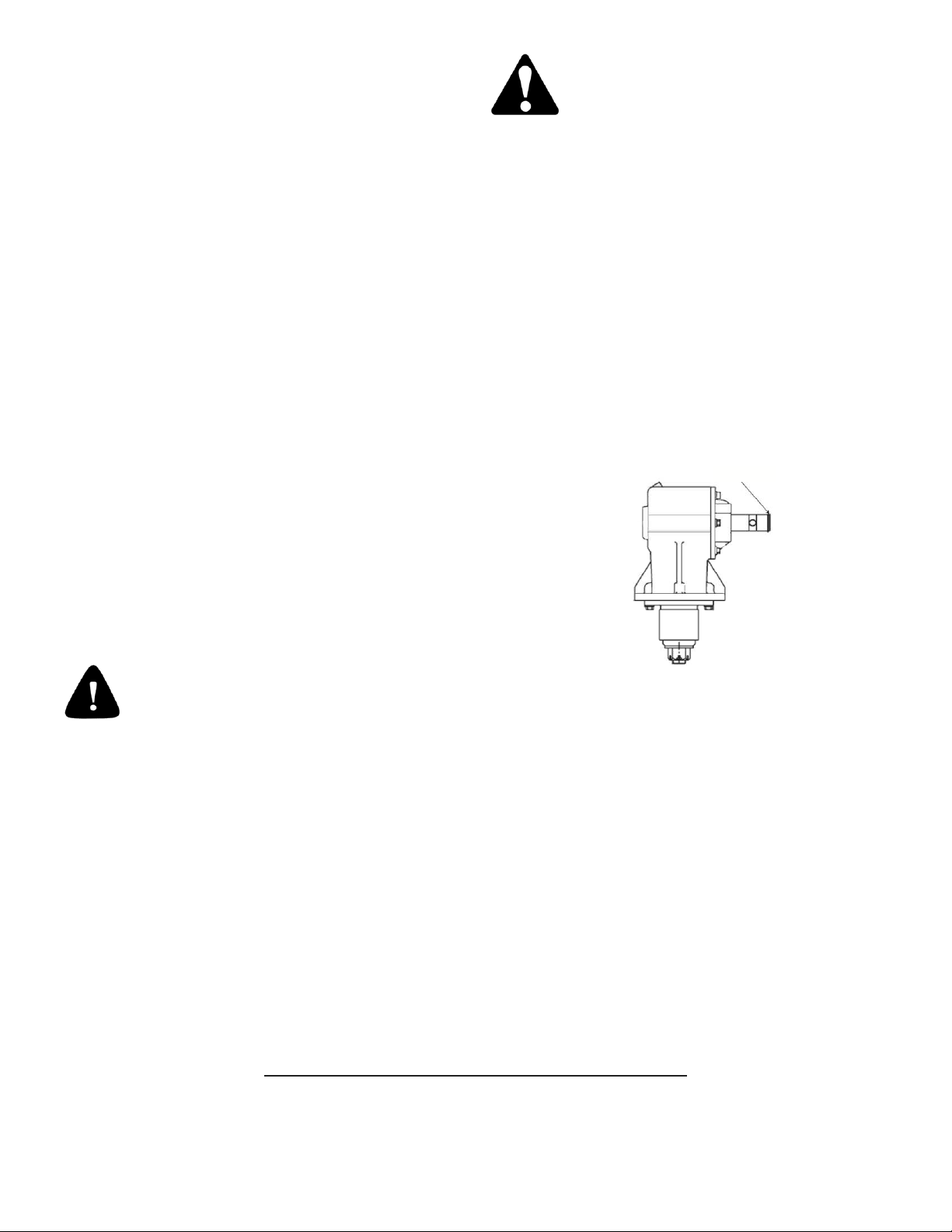
____ RMS GEARBOX has a driveline snap
ring already installed. The snap ring prevents the driveline
from swinging if the shear pin breaks while in operation.
• If the driveline is not connected to the gearbox, remove
the snap ring before connecting the Driveline to the gear-
box and immediately replace to secure the driveline.
• If the driveline is already installed, verify that the
snap ring is present!
Failure to use the snap ring may cause
serious injury or death!
WARNING
OSHA, ASABE, SAE and ANSI standards require the use of Chain Guards or other protective
guards at all times for non-agricultural use. Priefert Manufacturing strongly recommends that
such guards should be used for Agricultural uses as well, to minimize risk of property damage,
serious bodily injury or even death from thrown object hazards or by contacting rotating parts, i.e.
driveline, implement blades.
Dealer’s Signature ______________________________________________
Purchaser’s Signature ______________________________________________
Model Number: ______________________________________________
Serial Number: ______________________________________________
(Serial Number Plate location is shown on page 9)
Do not remove this checklist from the Operator’s Manual.
It is the responsibility of the dealer to complete the procedures listed above
before delivery of this implement to the buyer.
Snap Ring

Table of Contents
Dealer Preparation Checklist 2
Important Federal Laws & Regulations 4
Welcome 5
Getting Started.......................................................................... 5
Terminology .............................................................................. 5
Owner Assistance..................................................................... 5
Customer Service ..................................................................... 5
Safety 6
Safety........................................................................................ 6
Signal Words ............................................................................ 6
Personal Protective Equipment ................................................ 7
Emergency Preparedness ........................................................ 7
No Passengers Allowed............................................................ 7
Shutdown & Storage................................................................. 7
Equipment Safety Guidelines ................................................... 7
Transportation........................................................................... 8
Maintenance and Your Safety .................................................. 8
Safety Labels ............................................................................ 9
Section 1: Set-Up Requirements 10
Tractor Requirements .............................................................. 10
Three-Point Hitch..................................................................... 10
Tractor Hook-Up ...................................................................... 10
Driveline Installation................................................................. 11
PTO Driveline .......................................................................... 11
Determine Operating Lengths 11
Driveline Adjustments 12
Slip Clutch Specifications 13
Driveline Protection 13
Gear Box Oil Requirements ..................................................... 14
Section 2: Adjustments 15
Slip Clutch Adjustments........................................................... 15
Deck Leveling .......................................................................... 15
Deck Mowing Height................................................................ 16
Center 3-Point Link Length ...................................................... 16
Gauge Wheel Height Adjustment (FMX Models)..................... 16
Wheel Interference Check (FMX Models)................................ 16
Tail-Wheel Height Adjustment ................................................. 17
Belts and Sheaves (FMX Models) ........................................... 17
Belt Tension (FMX Models) ..................................................... 17
Sheaves (FMX Models) ........................................................... 17
Section 3: Operating Instructions 18
Operating Check List ............................................................... 18
Inspection Procedures ............................................................. 18
Transporting Procedures ......................................................... 18
Unhooking the Implement........................................................ 19
Mowing Safety ......................................................................... 19
Section 3: Operating Instructions (Continued)
Before Mowing ......................................................................... 20
General Operating Instructions ................................................ 20
General Operating Procedures ................................................ 20
Transporting Instructions.......................................................... 21
Mowing Instructions..................................................................21
Taking a Break ......................................................................... 21
Section 4: Maintenance 22
Servicing...................................................................................22
General Maintenance ............................................................... 22
Maintenance Schedule............................................................. 22
Blade Maintenance ..................................................................22
Blade Sharpening..................................................................... 22
Blade Replacement..................................................................22
Shear Bolt Replacement .......................................................... 22
Blade Spindle Maintenance (FMX Model)................................ 22
Driveline Maintenance.............................................................. 23
Lubricating................................................................................ 23
Gearbox.................................................................................... 23
Replacing Oil............................................................................23
Handling Waste Product and Chemicals.................................. 23
Parking & Storage .................................................................... 23
Section 5: Specifications 24
FMX Models ............................................................................. 24
RMS Models............................................................................. 25
RMX Models............................................................................. 26
RMH Model .............................................................................. 27
Section 6: Components 28
Mower Components (All Models) ............................................. 28
Decals ......................................................................................39
Section 7: Appendix 30
Troubleshooting Mower............................................................ 30
Troubleshooting Gearbox......................................................... 30
Troubleshooting Drivelines....................................................... 31
Maintenance Record 31
Warranty 32
References 33
3

IMPORTANT FEDERAL LAWS AND REGULATIONS
FOR OPERATORS, EMPLOYERS AND EMPLOYEES
This section is not intended as a legal interpretation of the laws and regulations and should not be considered as such. The following information is
intended to explain the concept and effect in the broadest of terms only.
U.S. Public Law 91-596 (Occupational Health and Safety Act of 1970) “To assure safe and healthful working conditions for working men and
women; by authorizing enforcement of the standards developed under the Act; by assisting and encouraging the States in their efforts to assure safe
and healthful working conditions; by providing for research, information, education, and training in the field of occupational safety and health; and for
other purposes.”
SECTION 5 DUTIES
a) Each employer
(1) shall furnish to each of his employees employment and a place of employment which are free from recognized hazards that are causing
or are likely to cause death or serious physical harm to his employees;
(2) shall comply with occupational safety and health standards promulgated under the Act.
b) Each employee shall comply with occupational safety and health standards and all rules, regulations, and orders issued pursuant to this Act which
are applicable to his own actions and conduct.
OSHA Regulations
Title 29, Code of Federal Regulations Part 1928 (29 CFR 1928) - Occupational Safety and Health Administration. (OSHA) , as well as,
Title 29 Code of Federal Regulations Part 1910 (29 CFR 1910 Parts 142, 266, 1200 and 1027) also contain applicable training standards.
Training Requirement
(6) Operating Instructions. At the time of initial assignment and at least annually thereafter, the employer shall instruct every employee in the
safe operation and servicing of all covered equipment with which he is or will be involved, including at least the following safe operating
practices.
(i) Keep all guards in place when the machine is in operation;
(ii) Permit no riders on farm field equipment other than persons required for instruction or assistance in machine operation;
(iii) Stop engine, disconnect the power source, and wait for all machine movement to stop before servicing, adjusting, cleaning, or
unclogging the equipment, except where the machine must be running to be properly serviced or maintained, in which case the
employer shall instruct employees as to all steps and procedures which are necessary to safely service or maintain the equipment;
(iv) Make sure everyone is clear of machinery before starting the engine, engaging power, or operating the machine;
(v) Lock out electrical power before performing maintenance or service on farmstead equipment.
Title 29, Code of Federal Regulations Part 570.70 (29 CFR 570.70) subpart E-1 — Child Labor Under 16 Years Old
The child labor rules that apply to agricultural employment depend on the age of the young worker and the kind of job to be performed. The rules
are the same for all youth, migrant children as well as local resident children. In addition to the restrictions on hours, the Secretary of Labor has
found that certain jobs in agriculture are too hazardous for anyone under 16 to perform. Specifically under the age of 16 may not operate power
machinery. It is your responsibility to know what regulations are in your own area or situation.
4

Welcome
Priefert Manufacturing would like to thank you for choosing the best
built implement on the market today. With proper care and mainte-
nance your implement will last for years to come.
Priefert offers a variety of implements to fit any application. The capa-
bility of our mowing implements range from light duty (RMS) models
(non-commercial use) that will give your small farmstead a professional
appearance to our heavy-duty commercial grade RMH model.
Priefert Manufacturing maintains an ongoing program of continuous
product improvement. Therefore, Priefert reserves the right to make
improvements in design or specification changes without incurring any
obligation to replace said items on units previously sold.
There is a possibility that some illustrations in our manuals were of
prototype models, design of production models may vary in detail from
those shown in our manuals.
IMPORTANT: Some photographs or illustrations may show safety
shields removed for purposes of clarity. DO NOT OPERATE THIS
IMPLEMENT WITHOUT ALL SAFETY SHIELDS IN PLACE!
REMEMBER SAFETY FIRST!
Be Alert - Eliminate unsafe habits and risky behavior, recognize
hazards as they exist and read and follow the Operator’s Manual
for your Priefert implement and your tractor!
Getting Started
This manual provides information necessary to effectively and safely
operate your implement. This manual also provides manufacturer’s
recommendation of proper use and maintenance of the implement.
The information presented in this operator’s manual is applicable
only to the make and model of your implement at time of purchase.
See your authorized dealer or manufacturer for any needed addi-
tional information.
Terminology
“Right” or “Left” as used in this manual is determined by facing
forward in the direction the machine will operate while in use
unless otherwise stated.
“NOTE:” provides the operator a brief summary of information that will
assist in operating the implement.
“IMPORTANT:” denotes that the following content has significance in
the operation or maintenance of the implement.
Owner Assistance
Please contact your Priefert Dealer if you have any questions regard-
ing your implement, need repairs, or to order replacement parts.
The parts on your implement have been specifically designed and
should only be replaced with approved Priefert Manufacturing parts.
Customer Service
Contact your Priefert Dealer and allow them the opportunity to discuss
assist in correcting any problems that you may be experiencing.
For further assistance write to:
Priefert Manufacturing
Attention: Customer Service
2630 South Jefferson
P.O. Box 1540
Mount Pleasant, Texas 75456-1540
1-800-527-8616
Web-site address:
www.priefert.com
sales.priefert.com
5

For the Safe Operation of Your Priefert Implement:
Owner and operator’s responsibilities are to read and understand the Operator’s Manual before operating the implement! This alert
symbol found throughout this manual is to call your attention to the extra safety precautions within the instruction. All safety symbols
are designed to ensure safe operation of your implement. Your safety and the safety of others depends upon your being alert, informed
and properly trained while operating, transporting, storing and performing maintenance. Failure to understand follow the instructions
included in this Operator’s Manual may result in serious injury or death.
Your Operator’s Manual contains the “Safety Label” decals that have been installed on your implement to warn you of certain potential
hazards that exist. These safety decals are not substitutes for reading and understanding this Operator’s Manual.
Do not allow anyone to operate this equipment who has not fully read and comprehended this manual and who has not been properly
trained in the safe operation of the equipment.
• Operator should understand all functions of the tractor and implement.
• Do not attempt to operate implement from the ground or from the back of the tractor; operate implement from the driver’s seat only.
• Inspect all guards and shields to ensure that these are in place, in good condition, and secured before operating the implement.
DO NOT OPERATE if any guards or shields are missing or not in operating condition!
• Always follow the proper shut down procedure for both the implement and the tractor any time you have to leave them unattended.
• Dismounting while a tractor is moving could cause serious injury or death.
• Never allow anyone to stand between the tractor and implement while an operator is backing up to the implement, or if PTO is engaged as
this may cause serious injury or death.
• Keep hands, feet, hair, jewelry, and clothing away from equipment to avoid entanglement with power-driven parts.
• Watch out for obstacles such as bushes, fencing, trees, power lines, etc., when raising implement.
• Clear the work area of all bystanders, children, pets, livestock, etc., during operation.
• Avoid sharp turns as this may cause implement to ride up on the tractor’s wheels that may result in serious injury and damage to
your equipment.
• Your implement is not designed to carry passengers - No Riders!
SIGNAL WORDS: The appropriate signal word for each identified
hazard has been selected using the following guidelines: 1
DANGER Indicates an imminently hazardous situation, which, if not
avoided, will result in death or serious injury. This signal word is limited to
the most extreme situations, typically for machine components that, for
functional purposes cannot be guarded. 1
CAUTION Indicates an imminently hazardous situation, which, if not
avoided, may result in minor or moderate injury. It may also be used to
alert against unsafe practices. 1
WARNING Indicates a potentially hazardous situation which, if not
avoided, could result in death or serious injury, and includes hazards that
are exposed when guards are removed. It may also be used to alert
against unsafe practices.1
Safety
6

Personal Protective Equipment
• Do not wear loose fitting clothing, dangling jewelry, long hair should be tied back to avoid entanglement.
• Wear steel-toe boots or other appropriate footwear. Soft cloth shoes or sandals are not safe around any
type of equipment.
• Wear hearing protection such as earplugs or other devices that will minimize sounds, but will not interfere
with your ability to hear traffic or other noises that may alert you to potential hazards.
• Do not operate any machinery while talking on a cell phone or using other portable devices such as MP3 players,
as these are considered distractions. Operating any farm equipment requires the operator’s full attention.
Safety
Emergency Preparedness
• Keep a fire extinguisher on your tractor and check the expiration date periodically!
• Keep a well stocked first aid kit on your tractor.
• Save In Case of Emergency ( I.C.E ) numbers on your cell phone (including doctors, hospital and
911 services).
• Keep I.C.E. numbers next to a home or office phone.
No Passengers Allowed!
• Passengers may obstruct the operator’s view that may result in an accident.
• This implement is not designed to carry passengers and may cause failure in the PTO driveline or other
malfunctions that may result in serious injury or death.
Shutdown and Storage
• Disengage PTO driveline before inspecting, working around the driveline or during shutdown.
• Lower machine to ground, put tractor in park, turn off engine, and remove the key.
• Detach and store implements in an area where children normally do not play.
• Secure implement by using blocks and/or supports.
Equipment Safety Guidelines
• Review safety instructions for both the tractor and this implement annually.
• Never exceed the limits of the tractor or the implement.
• If the ability to accomplish the job or to operate safely is in question, DO NOT TRY IT!
• This equipment is dangerous to children and those unfamiliar with it’s operation. DO NOT ALLOW children
to operate or play on the equipment.
• Operator should be an adult who is familiar with operating the tractor and the implement.
• Operator should be physically and mentally fit before operating machinery. Fatigue, stress, medications,
alcohol and drugs may impair the ability to focus on safe farm machinery operation.
• Check all equipment before operating this implement.
• Refer to the tractor’s operator manual for additional safety information (such as hydraulic pressure,
tire safety, etc.)
• Check all safety decals and/or signs - if any of these have been damaged, illegible, removed or parts
replaced without these decals, new decals must be reapplied. Contact your local Priefert Dealer or our
office to order replacements.
7

Transportation
A high percentage of fatalities and injuries involve farm equipment on
roads and highways. It is very important to use common sense while
operating equipment and vehicles.
1. Plan your route.
2. Be aware of surface conditions, visibility, pedestrian and vehicular
traffic, curves, on-ramps and intersections.
3. Safest time to transport farm equipment on public roads is between
sunrise and sunset.
4. Ensure that the hitches are properly secured and fastened.
5. Use the Slowing Moving Vehicle (SMV) emblem, if required by your
local and state laws, properly attached and visible.
• Comply with state and local laws.
• Perform a safety inspection on the tractor and correct any hazards
before you begin operating equipment.
• Use approved lighting, flags, and necessary warning devices on
your farm equipment to alert other vehicles on the highway.
• Inspect all warning lights and turn signals be sure these are
operational. If necessary you may need to purchase accessory
lighting devices that are available through your tractor dealership
or farm equipment store.
• Use the safety devices that are installed on your tractor such as
ROPS, and seat belts. Never modify any safety device that has
been provided with your equipment.
• Reduce speed if towed load is not equipped with brakes.
• Keep the brake pedals locked together at all times and make sure
the brakes are properly adjusted.
• 20 MPH is the maximum transport speed for towed implements
without brake devices. DO NOT EXCEED.
• If your tow weight is double the weight of the tractor do not exceed
10 mph.
• If towed weight is more than double the weight of the tractor do not
operate the equipment; select a larger tractor.
• Operator must have control of steering and braking at all times.
Slow down if your travel speed affects handling of farm equipment.
• Slow down for turns and curves and avoid sudden uphill turns.
• Sudden braking may cause loss of control over the implement.
• Never travel at a speed which does not allow adequate control
of steering or lessens the ability to stop. Some rough terrain
may require a slower speed.
Maintenance and Your Safety
Read and understand the Operator’s Manual before performing any
maintenance. If you are unfamiliar with performing maintenance then
enlist someone with experience to assist you.
• Wear appropriate protective clothing such as steel-toe boots, eye
protection, gloves, etc.
• Work in a clean dry area.
• Buildings should have adequate ventilation for the starting, run-
ning, and stopping of machinery while performing maintenance
and/or repairs.
• Park the tractor and implement on level ground, disconnect the
PTO and remove the key.
• Allow your equipment to cool completely.
• Raise or lower the implement to the height needed to perform
maintenance or repairs. Blocks and/or jacks should be used to
prevent machinery from moving or falling.
• Never attempt to grease or oil implement while in operation.
• Perform routine maintenance regularly and in accordance with
the Operator Manual.
• Inspect your implement before and after each use; any worn or
broken parts should be replaced immediately. Repair in accor-
dance with the Operator Manual.
• Clean your implement after every use; and wipe away any excess
grease or oil that may have accumulated.
• Check brakes, safety chains, blades, pins and clevis for wear,
breaks, missing parts or cracks.
Safety
8

Safety Labels
Your implement comes equipped with all safety labels in place.
They were designed to help you safely operate your implement.
1. Read and follow their directions.
2. Keep all safety labels clean and legible.
3. Replace all damaged or missing labels. To order new labels
go to your nearest Priefert Dealer.
4. Some new equipment installed during repair requires safety
labels to be affixed to the replaced component as specified by
Priefert. When ordering new components make sure the correct
safety labels are included in the request.
5. Refer to this section for proper label placement.
To install new labels:
1. Clean the area the label is to be placed.
2. Wipe the surface dry.
3. Peel backing from label.
4. Press firmly onto the surface.
Use a small straight edge plastic (credit card) to squeeze out air bubbles
working from the center out towards the sides.
Safety
9

Section 1: Set-Up Requirements
Tractor Requirements
This unit is shipped completely assembled. Carefully follow instructions
for final assembly. Hitch clevises and lock pins are sold separately.
RMX and RMH models are designed with a 3-point category I hitch, which
may be adapted to a category II. The RMS model is designed with a
3-point category I hitch and will require an adjustment to fit a category II
hitch. Horse power rating of the tractor should not exceed the PTO rating
of the gearbox.
*May require the use of hitch bushings.
Three-Point Hitch
See Chart below for Tractor Categories and Three-Point Standards
The stabilizing arms are the 2-steel or cast arms that extend rearward
and provide the lift and are the pull-point for the implement (referred to
as lower link). The Upper Link is the 3rd mounting point and extends
from a top middle position at the rear of the tractor. Comparatively little
rearward force is applied from the top link.
The implement has been designed for front to back flotation while mov-
ing on uneven terrain. Adjust the tractor’s top link to place the upper
hitch vertically above the lower lifting arms.
Tractor Hook-Up
1. If your tractor has a multi-speed PTO, be certain that the PTO is
set for 540 RPM.
2. Back tractor up to implement until lower 3-point links are aligned
with the hitch clevises on your implement. Always stop the trac-
tor, set the brake, shut off engine and remove the key before
dismounting from tractor.
3. Secure tractor’s 3-point lower links to the lower hitch clevises
using 7/8" hitch pins. Use appropriate hitch pins for your hitch
classification. Refer to “Tractor Categories and Three-Point Hitch
Specification” table below.
4. Secure the tractor’s top link to the implement’s top hitch using a
3/4” hitch pin (supplied by customer). Adjust the tractor top link in
order to level the implement.
5. Start tractor engine and lift implement from the ground about 12-
14 inches. Turn off the tractor.
6. Adjust the tractor’s 3-point hitch lift height so that the implement is
not lifted more than 14'' off the ground while the PTO Driveline is
attached to implement and tractor to avoid damaging the driveline.
7. Install the stabilizer arms, anti-sway blocks or chains, refer to your
tractor’s operating manual to limit side sway of hitch. Side to side
oscillation of about 2 inches is recommended.
8. Level the implement at the sides by adjusting the tractor lift links.
9. Measure the blade tip height on both sides, if these are not the
same refer to Section 2 “Adjustments for Deck Mowing Height” on
page 16.
10. Mount the driveline to determine if this needs to be adjusted.
11. Carefully raise and lower the implement and ensure that tractor’s
tires, drawbars, and other equipment on the tractor do not come
into contact with the implement’s frame or PTO Driveline.
12. Use the lift control limiting stop on the tractor control lever to limit
the upward travel of the lever so the lift cannot be raised high
enough to cause contact between the drive shaft shield and front
shielding.
Model
Width
Hitch
Type
Recommended
Maximum HP
FMX500 5'
I/ II* 40
FMX600 6' I/ II* 50
RMS400 4'
I 40
RMS500 5'
I/ II* 60
RMS600 6'
I/ II* 60
RMX500 5'I/ II* 60
RMX600 6'I/ II* 75
RMH700 7'
II 90
3
Tractor Categories and Three-Point Hitch Specifications
10
Category
Hitch Pin Size Lower Hitch Spacing
(Spread)
Upper Link Lower Link
Inches Metric Inches Metric Inches Metric
I
3/4”
19mm
7/8”
22.4mm
26”
718mm
II
1”
25.5mm
1-1/8”
28.7mm
32”
870mm
III
1-1/4”
31.75mm
1-7/16”
37.4mm
38”
1010mm
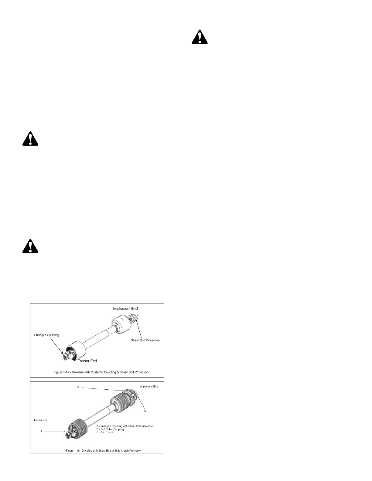
Driveline Installation
The FMX and RMS model driveline is connected with a push-pin coupling
to the tractor and a shear bolt coupling to the implement. Refer to
Figure 1-1a Driveline with Push-Pin Coupling. The RMX uses a
push-pin coupling to the tractor and a 2-plate slip clutch to the implement.
The RMH uses a push-pin coupling to the tractor and a 4-plate slip
clutch to the implement. Refer to Figure 1-1b Driveline with Slip
Clutch Coupling.
To minimize torque on the driveline when starting up; remember to
always engage the PTO at a low engine RPM.
Note: If your Priefert implement is equipped with a friction clutch; then
it must go through a “run-in” operation prior to initial use and after long
periods of inactivity. (Refer to Slip Clutch Specifications on page 13) .
CAUTION
Tractor PTO shield and all implement guards must be in place at
all times during operation!
IMPORTANT: If you are switching tractors or going to use a quick
connect hitch then you will need to check the driveline maximum and
minimum lengths to ensure the safe operation of your equipment.
You may find it necessary to use different drivelines.
IMPORTANT: Before connecting the PTO Drivelines, clean and lubri-
cate driveline connection points. When checking PTO driveline mini-
mum length, it is important to have the tractor’s PTO driveline level
with the implement’s gearbox shaft. Engage the tractor’s hydraulic 3-
point to raise or lower the lower arms until the implement’s gearbox
shaft is level with the tractor’s PTO Shaft.
DANGER
Priefert advises against the use of PTO adapters as these may
defeat the purpose of the master shield on your tractor. PTO
adapters create an unguarded shaft area between the tractor
and the driveline guards that may cause entanglement that may
result in serious injury or death.
DANGER
Do not attempt to operate your PTO driveline while it is
unguarded as this may cause entanglement that may
result in serious injury or death.
PTO Driveline:
Refer to Figures 1-2 to determine minimum and maximum operating
lengths on page 12.
The PTO driveline minimum and maximum lengths must be checked
prior to initial use or when using a different tractor or adding a quick
connect hitch and to ensure that the driveline is compatible with all
work conditions required by your Priefert implement.
When fully extended the driveline must have a minimum overlap of the
inner and outer shafts by not less than 1/3 the free length with both inner
and outer shafts being of equal length or not less than a 6" (76mm)
overlap.
Telescoping drivelines will have a variant in lengths due to changes in
the vertical angle of +20odue to uneven terrain or raising implement for
transport. It is very important not to operate your driveline with less
than the 1/3 free length or 6” (76mm) overlap as this may cause your
driveline to detach while in operation and pose a safety hazard to the
operator and possible damage to the tractor and implement.
1. Attach implement to your tractor. (See "Tractor Hook-up", pg. 10)
2. Adjust tractor top link until the implement gearbox input shaft is
level with tractor input shaft.
3. Place tractor gear selector into park, turn engine off, set park
brake and remove key.
4. Securely block implement in this position.
5. Attach the PTO driveline to the implement’s shaft:
For Driveline with slip clutch—secure by sliding the Slip clutch end
of driveline over the splined input shaft of the gearbox. Secure with
driveline yoke locking device. For Driveline with Shear Bolt—secure
by sliding the shear bolt end of the driveline to the implement’s shaft
of the gearbox. If the driveline comes with a snap ring ensure that
this is locked into place and shear bolt is tight.
6. Slide the opposite driveline yoke end over the tractor’s splined
driveline shaft. Secure with driveline yoke locking device. The
driveline will require shortening if it is too long to fit between the
tractor and implement then continue with Driveline Adjustment.
If the PTO driveline fits the tractor and implement continue with
Slip Clutch Set-up Requirements.
7. If the PTO driveline does not fit between the tractor and the imple-
ment continue with “Determining your operating lengths”.
Determine your operating lengths:
1.Pull drive halves apart until fully extended, just before coming apart.
Record this measurement as A and subtract 6” (76mm) and record as
C measurement in your operator’s manual.
2.Push the driveline halves together. Record this measurement as B
and add 1” (25.4 mm) and record as D measurement in your operator’s
manual.
11
Section 1: Set-Up Requirements

Section 1: Set-Up Requirements
IMPORTANT: Never operate equipment with driveline extended
beyond measurement C. Never operate equipment with driveline
collapsed to less than measurement D. Before you begin the
driveline adjustments; Priefert strongly recommends that you
request your dealer to fit your driveline to your equipment.
Driveline Adjustment
Refer to Figures 1-2 for Minimum and Maximum Lengths.
IMPORTANT: Adjusting the PTO Driveline requires that all cuts be
made equally to the inner/outer guards and the inner/outer shafts.
1. Remove the PTO driveline from the tractor’s splined output shaft
and the implement’s splined gearbox.
2. Pull the inner and outer shafts apart.
3. Remove the PTO shields (guarding).
4. Attach the implement’s inner cylinder to the implement’s
gearbox shaft.
5. Pull on the implement’s PTO driveline to ensure that it is
securely attached.
6. Attach the tractor’s output shaft to the tractor’s PTO gearbox
shaft.
7. Pull on the tractor’s PTO driveline to ensure that it is securely
attached.
8. Raise and lower implement to find the shortest operating
distance between the gearbox input shaft and tractor’s output
shaft.
9. Hold both halves parallel to each other in the shortest operating
distance and mark them.
10. Measure the marks made in Step 9 and record them to shorten
the outer and inner guards equally.
11. Raise and lower implement to find the maximum operating
distance between the gearbox input shaft and tractor’s
output shaft.
12. Hold both halves parallel to each other in the maximum
operating distance and mark them.
13. Check that the driveline has a minimum of 6” (152.4mm) overlap
or 1/3 the total length of the driveline.
14. Measure the marks made in Step 13 and record them.
15. Disconnect the implement inner cylinder from the implement’s
gearbox shaft.
16. Disconnect the tractor’s output shaft from the tractor’s PTO
gearbox shaft.
17. Securely clamp the implement driveline guard shield section in a
bench vise and cut off the guard at mark. File off any burrs. Repeat
this step for the tractor driveline guard shield. Use one of these
sections to create a cutting guide for the shaft and cylinder.
18. Use a padded bench vise to securely clamp the implement
cylinder before cutting. Do not over tighten as this may damage
the cylinders.
19. Using the guard as a guide, mark the cylinder and cut. File any
burrs and clean off filings. Do not round the ends of the cylinder
when filing.
20. Repeat steps 12 and 13 to shorten the tractor driveline shaft.
21. Apply grease to the inner shaft.
22. Reassemble the driveshaft, and securely attach the driveline
guard.
23. Reattach the PTO driveline to the tractor and implement. Make
sure that these are securely attached before attempting to
engage the PTO driveline.
24. The driveline should now be moved back and forth to insure that
both ends are secured to the tractor and implement. Reattach
any end that is loose.
25. Hook driveline safety chain in the hole in the inner driveline
guard. Attach the other end to the implement’s main frame.
26. Hook driveline safety chain in the hole in the outer driveline
guard and attach the other end to the tractor main frame.
27. Start tractor and raise implement just enough to remove blocks
used to support the implement frame.
28. Slowly engage tractor’s hydraulic 3-point to lower the
implement. Check for sufficient drawbar clearance. Move
drawbar ahead, aside or remove if required to eliminate binding.
29. Check to make certain that the driveline overall length does not
extend beyond the maximum recorded length as in Step 14.
12

CAUTION
If the safety chains are not correctly fitted this will result in
excessive tension causing the safety hook to open on the protection
side. when this occurs it is necessary to replace the damaged hook with
an original one.
This chain must be attached to the inner driveline shield and to the
implement to restrict shield rotation.
Measurements:
Note: Do not use the driveline as a support or running board. Do not
use the anti-rotation chain to support or transport the driveline when it is
detached from the tractor. Use the storage bracket on the machine.
Slip Clutch Specifications
Slip (Friction) clutches have adjustable torque settings. The torque
setting varies with the different compression of each spring. All springs
should have an equal amount of compression (a sliding caliper or
measuring tape will aid in setup and adjustments). Your slip clutch
comes factory preset to the correct torque setting.
CAUTION
Slip clutches may become hot. Do Not Touch! Keep the slip
clutch area clear of any material that may catch fire!
Important: Do not over-tighten the compression bolts as this may
impair performance or cause premature wearing of the slip clutch!
• Before first use or after a long storage, loosen set screw on
pressure nut.
• Back off pressure nut to free clutch plates.
• Tighten pressure nut until the clutch plates are snug.
• Tighten pressure nut another 1/4 turn.
• Run the driveline at a low idle to slip the clutch until it starts to
smoke. This will remove the dirt, corrosion and surface gloss from
the clutch plate faces.
• Tighten the pressure nut another 1/2 turn to set the clutch plate
pressure.
• Tighten the set screw in the pressure nut to lock it in place. Normally
the clutch will slip at a 20% higher torque after the “run-in” than before.
• Check the temperature of the clutch after running for 20 minutes
and after every 8 hours of operation.
• If the clutch is hot to the touch or smokes reset the pressure nut or
the clutch plates will burn up and fail.
• Tighten the pressure nut in 1/4 turn increments and try during
operation.
• The clutch should be set so it does not slip during normal
operation. It should slip when the unit is overloaded from heavy
cutting or when striking an obstruction. If it is set for too high
torque to slip, components will fail.
Driveline Protection on RMS Model
For RMS models with PTO drivelines that have shear bolt protection;
ensure that you also secure the driveline using the snap ring that is
included after securing the driveline to the gearbox. Failure to do so may
result in serious injury or death. To remove or replace the snap ring use
snap ring pliers. If the snap ring is bent or cracked do not attempt to
operate the driveline. Immediately take the implement out of operation
until the snap ring is replaced.
Section 1: Set-Up Requirements
13
Section 1: Set-Up Requirements
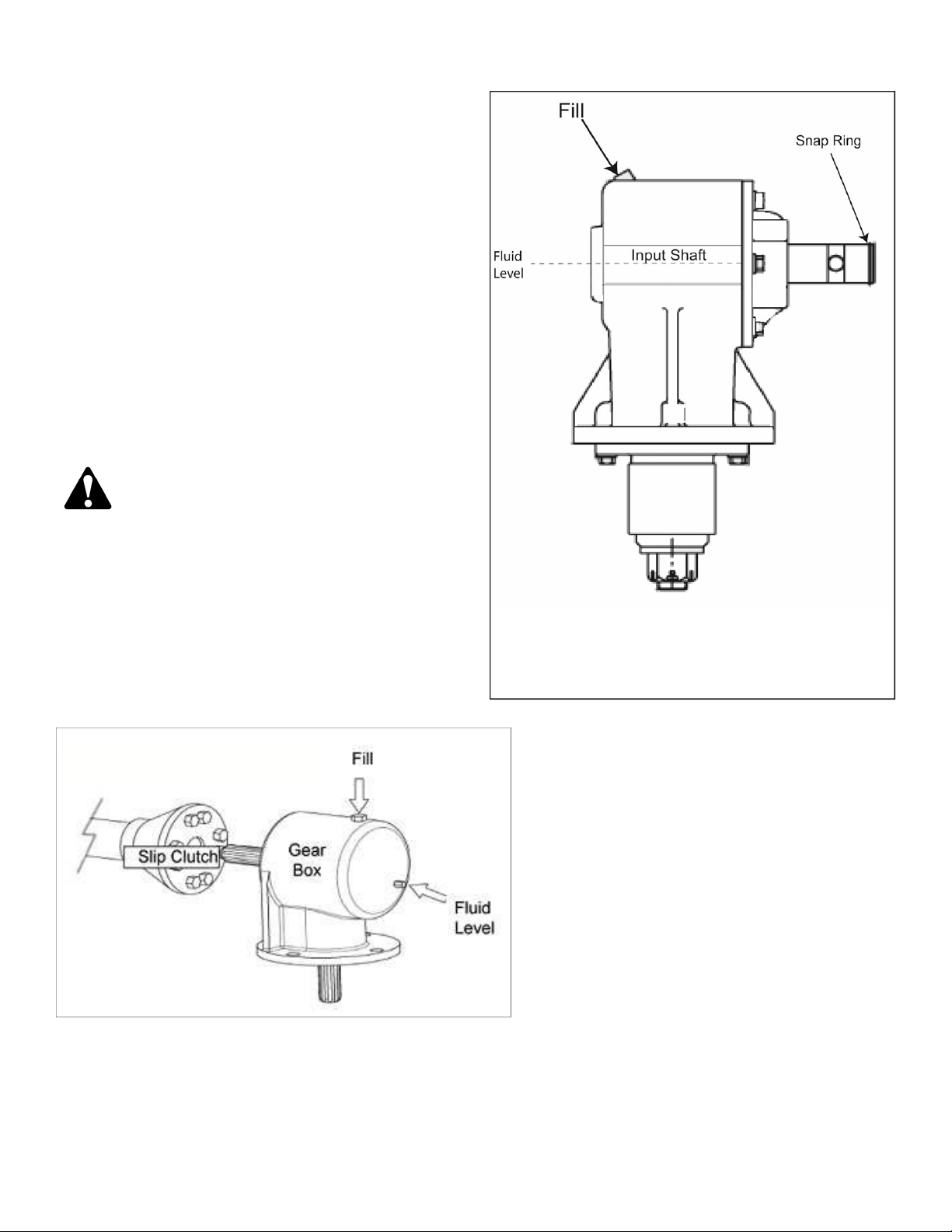
Gear Box Oil Requirements
Refer to Figure 1-4 and Figure 1-5
Before putting your implement into service:
IMPORTANT:
• Gearbox uses Multi-Purpose Gear Oil (ie: S.A.E. 80w/90 or
S.A.E. 85w/140 Multi-purpose gear oil.)
• For all Grease Fittings use TYPE/Grade II tube grease.
• Place implement so that the deck is secure and level.
• Clean away any excess oil and dirt before removing 1/2” Pipe Plug
(located at top of gearbox and 1/8” pipe plug (located at lower 1/3
of gearbox). Refer to figure 1-5 if your gearbox does not have a
fluid level plug as shown in Figure 1-4.
• Fill gearbox until the oil level is even with the bottom opening of the
1/8” pipe plug hole. *Refer to Figure 1-5 to check oil level if your
gearbox does not have the fluid level plug.
• Grease wheel axles (4), tail wheel (1), front roller axle (1), and PTO
Shaft universal joints (2).
• Check all bolts, nuts and belt to insure they are tight and secure.
CAUTION:
DO NOT overfill gearbox!
This could cause damage to oil seals, and can cause permanent damage
to the gearbox.
This issue will not be covered under warranty.
14
Figure 1-4—Slip Clutch and Gear Box
Figure 1-5—Gearbox without Fluid Level Plug
When filling you will need to visually check the oil level in the gearbox
through the fill opening. Fluid level should come half-way up the
input shaft as shown above; otherwise you may overfill the gearbox.

Section 2: Adjustments
Slip Clutch Adjustment
Figure 2-1a—Slip Clutch Adjustment and Figure 2-1b Spring
Compression
The slip clutch is designed to slip while under excessive torque to protect
the gearbox and drivelines, should the implement strike an obstruction.
This slip clutch is factory preset to the correct torque for protecting the
implement and the tractor PTO. A new slip clutch or one that has been
stored over the winter may seize. Before operating, make sure it will slip by:
1. Make sure tractor engine is turned off and key is removed.
2. Loosen the eight nuts retaining the springs by a 1/3 to 1/4 turn or
until you can turn the springs.
3. With tractor at idle speed, engage the tractor’s PTO drive for 2 to 3
seconds. If the clutch slips without turning blades skip to step 4.
If the clutch does not slip freely, disassemble and clean the clutch
face plates, yoke and plate and clutch hub—reassemble the clutch
and test again. If clutch continues to slip even though the springs
are compressed to the proper length, then check the friction disc
for excessive wear. Discs are 1/8” when new, if discs are less than
1/16” then replace with new discs. Contact your local authorized
Priefert dealer for further assistance.
4. Tighten each of the eight nuts until the springs are compressed to
the necessary tightness. Ensure that all compression bolts are set
to the same compression depth.
5. Check all spring lengths are the same (H); adjust nut on any spring
that is unequal in length. Refer to Figure 2-1b—Spring Compression.
Important: Failure to retighten nuts may cause damage to implement
and/or tractor due to improper slip clutch torque setting!
Note: Adjustment of the slip clutch is to provide only enough torque
to prevent slippage under normal operating conditions. Occasional
slippage is normal and provides protection to the driveline. If you are
not satisfied with your results please contact your local authorized
Priefert dealer for further assistance.
Leveling Procedure
There are 4 primary adjustments that should be made prior to actual
field operations:
1.Deck leveling from left to right.
2.Tractor top link length.
3.Tractor lower link height.
4.Tail-wheel height.
Proper adjustment of each of these items will provide for higher
efficiency, improved cutting performance and longer blade life.
The following tools will be needed:
•Pliable tape measure.
•Spirit or carpenters level.
•Open end or hex end wrench or socket set.
•Protective gloves.
DANGER
Engage parking brake, disengage PTO, shut off tractor and
remove key before proceeding. Ensure that all moving parts have
come to a complete stop before dismounting the tractor.
Deck Leveling From Left to Right
Refer to Figure 2-2:
1. Locate tractor with implement on a flat, level surface.
2. Use tractor’s hydraulic 3-point control lever to lower implement
until the tail-wheel makes contact with the ground surface.
3. Place a level or another suitable leveling device on the front of
the implement’s deck as shown in Figure 2-1. Manually adjust
either one or both of the tractor’s lower 3-point arm height
adjustments to level the deck from left to right. Some tractors
have only a single adjusting crank.
15
Figure 2-1b—Spring Compression
Figure 2-2—Deck Leveling
Figure 2-1a—Slip Clutch Adjustment

Section 2: Adjustments
16
Deck Mowing Height
Refer to Figure 2-3 Deck Mowing Height (applicable to RMS, RMX
and RMH
CAUTION
Wear a pair of gloves when performing this operation and
ensure the tractor is shut off and key is removed! Go to the back
of the implement and carefully rotate each blade to the position
shown in Figure 2-2. Avoid direct contact with the cutting edge
of the blade.
IMPORTANT: The blades should be positioned to cut material only at the
front of the implement. If deck is level or back of implement is lower than
the front, then the blades are subject to continuous material flow resulting in
additional blade wear, horsepower loss and frequent blade sharpening.
1. Using tractor’s 3-point hydraulic control, raise or lower the 3-point
arms until the front of the deck is slightly lower than the rear of
the deck.
2. The top center link should be loose when deck rear is supported by
the tail-wheel. If not, lengthen center link until loose. Final adjust-
ment will be made later.
3. With gloves on, carefully rotate each blade tip to the position shown
in Figure 2-3 on page 14.
4. Measure distance from cutting tip of blade to ground surface. This
distance is the cutting height.
5. If desired cutting height cannot be obtained by adjusting the lower
3-point arms then readjust tail-wheel height refer to “Tail-wheel
Height Adjustment” for RMS, RMX and RMH on this page.
For FMX adjust the gauge wheel height. Refer to “Gauge Wheel
Height Adjustment on this page.
6. Repeat Steps 1-5 until desired cutting height is achieved.
7. Set tractor’s 3-point hydraulic control stop at this height.
Center 3-Point Link Length on RMS, RMX and RMH Models
1. Lower implement deck to the normal cutting height.
2. Adjust length of center 3-point link so that the upper pivot hitch rests
at a slight downhill position. This arrangement allows for optimum
ground contour following performance.
3. Lock center link in this position once correct length is achieved.
4. The second set of holes on the upper pivot hitch should be used
when tractor’s center 3-point link is too short.
Adjusting Center Point Top Length on the FMX Model
This upper link needs to be adjusted to allow for the mower to “float”,
but still is able to lift the mower for transport or to avoid obstacles. This
adjustment is subjective; however, we recommend that the upper link
be adjusted out enough that when the mower is lifted above operating
level that the gauge wheels remain on the ground for a moment before
the 3-Point eventually raises the mower into the transport position. The
second set of adjustment holes on the upper pivot hitch should be used
when tractor’s center 3-point link is too short.
Gauge Wheel Height Adjustment (FMX models)
Refer to Figure 2-4.
To adjust the mowing height the spacers must be suitably placed above
and/or below the axle bushings. Achieving the professional appearance
is by combining the spacers above or below the axle bushings on all
wheels.
The spacers allow for an adjustment range from 3/4” to a maximum of
3-1/4” in 1/2” increments on the FMX500 Priefert Finishing Mower.
The adjustment range for the Priefert Finishing Mower - FMX 600 is
5-1/4” in 1/2” increments.
1. To set the minimum cutting height: place all the spacers above the
axel bushings.
2. To set the maximum cutting height: Place all spacers below the
axle bushings.
3. Using the tractor’s 3-point lift; raise the mower and securely lock
into position.
4. Holding gauge wheel and yoke assembly up, remove the lock pins
from top of gauge wheel spindle.
5. Position full-length spacers and half-length spacers as needed to
achieve the desired mowing height.
6. Lower mower to the ground.
7. Repeat steps 1-3 if needed. Make certain that all gauge wheels
are adjusted to the same height.
Wheel Interference Check on FMX Model
Do not operate mower until this interference check has been performed.
If you change tractors, you must perform the check for that mounting.
1. Raise mower with tractor hydraulics to maximum height of
tractor lift.
2. Pivot both front gauge wheels forward and check that there is
clearance between gauge wheels and tractor tires.
3. If there is interference, you must move hitch pin to extended
position. Move tractor tires inward to obtain clearance or lower
mower until clearance exists. Set 3-Point quadrant stop so
mower cannot be raised beyond set point.
Figure 2-3 — Deck Mowing Height
Figure 2-4—Gauge Wheel Height
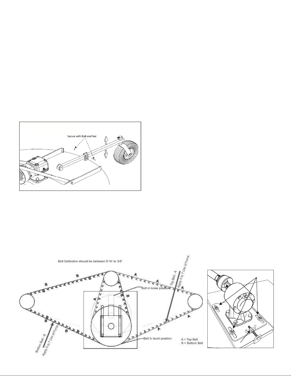
Figure 2-5—Tail-Wheel Height
Section 2: Adjustments
Tail-Wheel Height Adjustment (RMS, RMX, RMH Models)
Refer to Figure 2-5:
If deck slope is slightly lower at the front than at the back, and cutting
height is not at the desired height, then the tail-wheel must be adjusted
up or down as follows:
1. Use tractor’s 3-point hydraulic control to lift cutter until the tail-wheel
clears the ground. Remove carriage bolt and flange nut.
2. Adjust tail-wheel as follows:
3. To lower cutting height, adjust tail-wheel up.
4. To increase cutting height, adjust tail-wheel down.
5. With Tail wheel adjusted to the correct height, replace long carriage bolt
and flange nut. Tighten flange nut to the correct torque.
Readjust tractor’s lower 3-point arm height as needed.
See “Deck Mowing Height” on previous page.
Belts and Sheaves (FMX Models)
Refer to Figure 2-6
Belts
Ideal tension is the lowest tension at which the belt will not slip under
peak load conditions. Checking the tension during the first 24-48 hours
of run-in operation will lengthen the life of the belts.
Check belts before each use to keep the belts free from foreign material
which may cause slipping.
For maximum service, replace belts with a complete new set of belts to
maintain even tension on both sides. Never install a used belt as a
replacement unit of a set. Used belts are worn in cross-sections and are
stretched this will cause the belt to ride lower in the sheave, reduce
blade speed and may rupture the core centers causing the other belt to
elongate leaving one side of the mower under-belted. Belts from other
manufacturers should not be mixed for the same reasons.
Belt Tension (FMX Models)
1. To check tension, apply 7-10 lbs of pressure by pushing against
the belts halfway between the pulleys. The belt deflection should
be between 5/16” - 1/2”.
2. To adjust belt tension, loosen the (4) nuts holding the gearbox
support plate to the central plate (A). (Figure 2-6a)
3. Loosen the (2) locking nuts on the adjustment bolt (B).
4. Turn the adjustment bolt counter clockwise until the proper belt
tension is reached. This will draw the gearbox support plate to the
rear, thus tightening the belts.
5. Tighten the (2) locking nuts on the adjustment bolt (B).
6. Tighten the (4) nuts holding the gear box support to the central
plate (A).
Sheaves (FMX Models)
Check the condition of the sheaves before installing new belts. Rusty
or worn sheaves impairs the drive’s efficiency and will abrade the belts
prematurely. If the grooves are worn to where the belt bottoms, slip-
page may result and burn the belts. If the sidewalls are “dished out,”
the bottom shoulder wears off the bottom edge of the belt.
When replacing belts, ensure that the drive is shortened enough until
the belts can be put on the sheaves without forcing. Forcing belts may
cause internal damage to the belts and shorten belt life.
17
Figure 2-6 Belt Tensioning
Figure 2-6a Adjustment Nuts
A
B

Operating Check List
Hazard control and accident prevention are dependent upon the aware-
ness, concern, prudence and proper training involved in the operation,
transport, maintenance and storage of the implement. Therefore, it is
absolutely essential that no one operates the implement without first
having read, fully understood and become totally familiar with the Operator’s
manual. Make sure the operator has paid particular attention to:
• Safety, pages 6 - 9
• Section 1: Set-Up Requirements, pages 10 - 14
• Section 2: Adjustments, page 15 - 17
• Section 3: Operating instructions, pages 18 - 21
Also make sure the operator has completed the Operating Checklist
below before using your implement:
Read and follow the “Safety” section starting on page 6 carefully.
Read all of the “Operating Instructions” section on pages 18 - 21.
Review your tractor’s operating instructions.
Check the implement initially and periodically for loose bolts &
pins and tighten if needed.
Make sure all guards and shields are in place.
Check initially and periodically for loose bolts, pins and chains.
Know your controls and how to stop tractor, engine and PTO
quickly in an emergency.
IMPORTANT: Priefert strongly recommends that no children are
allowed to operate the rotary implement.
Inspection Procedures
Make the following inspections with implement attached to a tractor and
PTO disengaged and completely stopped.
DANGER
For RMS models with PTO drivelines that have shear bolt
protection; ensure that you also secure the driveline using the snap
ring that is included; failure to do so may result in serious injury or
death. To remove or replace the snap ring use snap ring pliers.
1. Inspect tractor safety equipment to make sure it is in good working
condition.
2. Carefully raise and lower implement to ensure that the drawbar,
tires, and other equipment on the tractor do not contact imple-
ment’s frame or PTO driveline.
3. Check that all hardware is properly installed.
4. With implement deck resting on solid supports, PTO disengaged
and completely stopped, check that the blades are sharp and
secure and properly positioned.
5. Check PTO guards to make certain they are in good working condi-
tion and in place.
6. Remove solid supports from under the deck and verify implement’s
front to rear and top link alignments.
7. Check that implement is level side-to-side and verify implement’s
deck is set to the correct height. See “Leveling Procedure” on
page 15.
8. Lubricate all grease fitting locations. Make sure PTO shaft slip joint
is lubricated.
9. Check to be sure gear lube runs out the small check plug on the
gearbox.
10. Make sure that the driveline operates freely and is seated firmly in
the tractor PTO shaft spline groove.
11. Set tractor PTO and transmission into neutral before starting engine.
12. Set tractor PTO select lever to 540 RPM.
13. The remaining inspections are made by engaging the PTO to
check for vibrations.
IMPORTANT: Stop PTO immediately if vibration continues after a few
revolutions during start-up and anytime it occurs thereafter. Wait for
PTO to come to a complete stop before dismounting from tractor.
Make necessary repairs and adjustments before continuing on.
• Start tractor, set throttle to idle or slightly above idle and slowly
engage PTO. Initial start-up vibration is normal and should stop
after a few revolutions. Stop PTO rotation immediately if vibration
continues.
• Once the implement is running smoothly, increase tractor throttle to
operating RPM. Stop PTO immediately if vibration occurs.
IMPORTANT: Do not exceed RPM rating. Excessive engine speed will
cause damage to the power train components.
Transporting Procedures
CAUTION
When travelling on public roads at night or during the day, use
accessory lights and devices for adequate warning to operators or
other vehicles. Comply with federal, state, and local laws
IMPORTANT: Always disengage the tractor’s PTO before raising
the implement to transport position.
1. Make sure driveline does not contact tractor or implement when raising
implement to transport position. If it is necessary to lift implement above
14”; always disconnect the tractor PTO driveline first.
2. Reduce tractor ground speed when turning, and allow enough clear-
ance so implement does not contact obstacles such as buildings, trees
or fences.
3. Limit transport speed to 20 mph. Transport only with a farm tractor of
sufficient size and horse power.
4. When traveling on roadways, transport in such a way that faster moving
vehicles may pass you safely.
5. Sudden braking can cause a towed load to swerve and upset. Reduce
speed if towed load is not equipped with brakes.
6. Shift tractor to a lower gear and use extra care when traveling over
rough terrain.
Section 3: Operating Instructions
18

Section 3: Operating Instructions
Un-hooking the Implement
Unhook the implement from the tractor as follows:
1. Disengage power to the driveline.
2. Park the implement on a level solid hard surface.
3. Lower implement to level ground or onto stable support blocks.
4. Engage tractor park brake, shut tractor engine off and remove key
before dismounting from tractor.
5. Disconnect driveline from tractor PTO shaft.
6. Un-hook 3-point hitch from tractor.
7. Reinstall hitch pins, lynch pins and hairpin cotters in implement
hitch for storage.
8. Connect driveline safety chains together.
9. Rotate driveline and place driveline into the grooved storage
bracket.
Mowing Safety
DANGER
Do not engage tractor PTO while hooking-up and unhooking the
driveline or while someone is standing near the driveline. A person’s body
and/or clothing can become entangled in the driveline resulting in serious
injury or death.
Tractor PTO shield, gearbox shield, and driveline shield must be
secured in place while operating the implement to avoid injury or
death from entanglement in rotating drivelines.
Damaged drivelines can break apart while rotating at high speeds
causing serious injury or death. Always remove the implement from
service until damaged drivelines are repaired or replaced.
Implements have the ability to discharge objects at high speeds.
Therefore, the use of front & rear deck safety shields is strongly recom-
mended while mowing along highways or in an area where people may
be present!
Do not cut on steep inclines. The tractor and implement could flip over
causing damage to the equipment, bodily injury or death.
Never carry a passenger on the implement. A rider can fall and be run
over by the implement or tractor causing serious injury or death.
Do not use implement to lift or carry objects. Lifting and/or carrying objects
can result in damage to the implement, serious bodily injury or death.
Never operate the implement while in the raised position. The implement
can discharge objects at high speeds resulting in serious injury or death.
Do not use the deck as a working platform. The deck is not properly
designed or guarded for this use. Using the deck as a working platform
can cause serious injury or death.
Do not use deck as a fan. Cutting blades are not properly designed or
guarded for this use. Using the deck as a fan can result in injury or death.
Do not use the driveline as a support or step.
Do not use the anti-rotation chain to support the driveline while it is
detached from the tractor. Use the grooved storage bracket on the
implement.
Do not allow anyone to stand between the tractor and the implement
during hookup. The Operator’s foot may slip off the clutch and back
over the assistant.
Do not operate machinery if you have consumed drugs or alcohol.
These will impair your judgment, alertness or coordination while
operating equipment. Seek medical advice if you are taking pre-
scription drugs before operating equipment.
Stay alert for hidden hazards, people, children entering into your work
area or traffic.
Do not leave the operator’s seat for ANY reason while the PTO driveline
is engaged and the tractor is running. Always disengage PTO, engage
parking brake, shut tractor engine off, remove switch key and wait for
blades to come to a complete stop before dismounting from tractor.
19

Section 3: Operating Instructions
IMPORTANT: It is important to maintain correct PTO speed. Loss
of PTO speed will allow blades to hinge back and result in ragged,
uneven cutting.
To reduce blade impact while striking obstacles; your rotary implement
is rigged with free swinging blades that will pivot or fold to absorb the
shock. However, it is best to ensure that the cutting height is adjusted
for the terrain in which you are mowing. This will extend the life of your
implement and will reduce premature blade wear or breakage.
Mowing should be avoided in extremely dry conditions as debris may
accumulate on your implement and may result in a fire due to heat
build-up caused by the friction of moving parts. In wet conditions
build-up of material on the underside of the implement will create a
loss of horsepower, increased wear and poor discharge and may
cause additional stress on the PTO driveline.
Know before you mow:
1. Check and mark potential hazards such as ditches, stumps, holes
or other obstacles that may cause the tractor to rollover or damage
the implement.
2. Inspect and clear the area for debris, and unseen foreign objects
such as branches, rocks, etc.
3. Develop a safe plan to avoid or minimize any safety hazards found
in steps 1 and 2.
4. Never assume the area is clear. Mow only in areas that you are
familiar with and are free of debris and unseen objects.
5. Extremely tall grass should be cut twice: first cut at the highest
possible cutting height to detect potential hazards, before cutting
at the desired cutting height.
IMPORTANT: Priefert strongly recommends that children should not
be allowed to operate this implement.
IMPORTANT: The PTO driveline while operating at 540 RPM is
actually rotating 9 times per second and at this speed the driveline
can pull clothing (for example) much faster than a human being can
take evasive action.
Note: Determining the correct ground speed depends upon two things:
The density of the material being cut and the size of the tractor powering
the implement.
Generally the quality of cut is better at lower ground speeds. Dense
ground cover will create the need to slow down even more. In certain
conditions the tractor tires will roll grass down resulting in uneven cut when
the grass fails to rebound. Should this happen you may try reversing the
direction of the cut and/or double cut to achieve the desired finish.
General Operating Instructions
It is important that you familiarize yourself with the Operator’s manual,
1) completed the Operator’s Checklist, 2) properly attached implement
to your tractor, 3) made leveling adjustments, and 4) preset your mowing
height.
You will need to maintain 540 RPM speed and 2 to 4 mph ground speed
to produce a clean cut. Make a tractor gear and range selection that
will enable you to maintain these speed combinations. If you need to
go slower, reduce your tractor speed by down shifting gears while
maintaining the 540 RPM - do not reduce speed of the PTO while
operating as this will impact the quality of the cut.
Note: Do not allow the implement to drop violently on the ground.
Violent impacts would strongly stress all machine components
and could cause damage to your implement.
General Operating Procedures
Perform an operational safety check by starting the implement.
It is important that at any time during this safety check you detect a
malfunction in either the implement or tractor that you immediately
disengage the PTO, shut the tractor off, remove it’s key, and make
necessary repairs and/or adjustments before continuing on.
1. Start the tractor and set the engine throttle speed at low idle.
Raise the implement with the tractor’s rear hydraulic lift control
lever to transport position making sure that the PTO shaft does
not bind and does not contact the implement’s frame.
2. Lower the implement to the ground and at a low engine speed
engage the PTO. If everything is running smoothly at a low idle,
slowly raise the implement to transport height checking for bind
or chatter in the driveline.
3. Lower the implement to the ground and increase the tractor’s
engine RPM until it reaches 540 RPM.
4. If everything is still running smoothly, once more raise the imple-
ment to transport height to check for driveline bind or chatter.
5. Lower the implement to the ground, return the engine to a low idle,
and disengage the PTO.
6. Position the adjustable stop on the tractor’s hydraulic lift lever so
the implement can be consistently returned to the same cutting
and transport height.
Avoid very low cutting heights especially on extremely uneven terrain.
Always cut downward on slopes and avoid crossing the face of the
steep slopes. Avoid sharp drops and cross diagonally through dips to
prevent hanging up the tractor and implement. Slow down in turns.
Remember to look back often.
DANGER
Keep hands and feet out! Do not step on or climb over the unit while
machine is in operation, or engine is running.
WARNING
Always disengage PTO, set parking brake, shut tractor off, remove
switch key and wait for blades to come to a complete stop before
dismounting from tractor.
CAUTION
Do not exceed rated mowing capacity of your implement! See Speci-
fications & Capacities for your model on pages 24-27 for specified
mowing Capacity. Using this implement for any other work can dam-
age the drive components, cutter blades, and deck components!
Do not over speed PTO or machine damage may result. This imple-
ment is designed to be used only with a tractor having a 540 RPM
rear PTO.
20
This manual suits for next models
11
Table of contents


