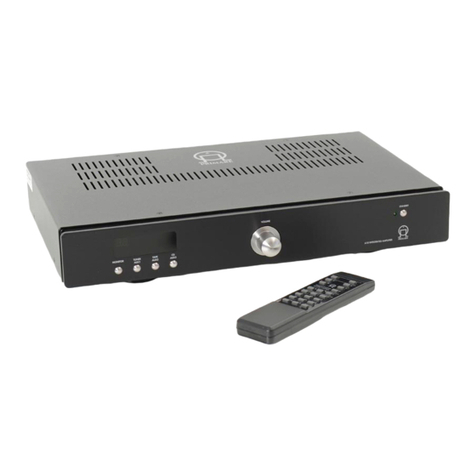
Primare A32 User manual

>
i
Primare A32 Amplifier User Guide
§0 Preface.pm7 1/12/05, 10:56 am1

>Preface
ii
COPYRIGHT AND ACKNOWLEDGMENTS
Copyright © 2005 Primare Systems AB. All rights reserved.
Primare Systems AB
Renvägen 1
SE-352 45 Växjö
Sweden
The information in this guide is believed to be correct as of the date of
publication. However, our policy is one of continuous development and so the
information is subject to change without notice, and does not represent a
commitment on the part of Primare Systems AB.
Primare is a trademark of Primare Systems AB. All other product names are
trademarks or registered trademarks of their respective owners.
This guide was produced by Human-Computer Interface Ltd,
http://www.interface.co.uk
FCC Warning: This equipment generates and can radiate radio frequency
energy and if not installed and used correctly in accordance with our instructions
may cause interference to radio communications or radio and television
reception. It has been type-tested and complies with the limits set out in Subpart J,
Part 15 of FCC rules for a Class B computing device. These limits are intended to
provide reasonable protection against such interference in home installations.
EEC: This product has been designed and type-tested to comply with the limits
set out in IEC 60065 7.
POWER CONNECTION
Warning: Before connecting power check that the required supply
voltage, indicated on the back panel, corresponds to your local AC
supply. If a different voltage is stated on the type plate do not connect the A32
Amplifier to the mains power, and seek advice from your dealer.
Safety instructions: To prevent fire or shock hazard, do not expose this
appliance to dripping or splashing. No objects filled with liquids, such as
vases, should be placed on the unit.
Do not place the unit near a heat source such as a radiator or fireplace.
If you want to build in the unit you need to be sure to allow space of at least
20cm behind, 10cm on both sides and 30cm above the top panel of the
unit. This is to prevent fire or damage caused by overheating. Also make sure
that the main switch is accessible.
Warning: Dangerous voltages inside. Do not open the cabinet. There are no
user serviceable parts inside. Repairs should be carried out by qualified
service personnel only.
Warning: In use the heatsinks will become too hot to touch (up to 70°C).
Replacing the fuses
Due to the large capacitance of the power supply smoothing capacitors, turn
off the mains power and wait at least 15 minutes before replacing a blown
fuse. Be sure to replace the fuse with one of the exactly same type and value.
§0 Preface.pm7 1/12/05, 10:56 am2

>
iii
Contents
Introduction
WELCOME TO THE A32 AMPLIFIER................ (1
USING THE A32 WITH OTHER PRIMARE
PRODUCTS................................................................ (2
TECHNICAL SPECIFICATION............................. (2
Connecting the A32 Amplifier
BACK PANEL CONNECTIONS........................... (3
POWER CONNECTION........................................ (4
OUTPUTS ................................................................... (4
INPUTS....................................................................... (4
STANDBY MODES................................................... (4
RS232 PORT............................................................ (5
Index
§0 Preface.pm7 1/12/05, 10:56 am3

>Preface
iv
§0 Preface.pm7 1/12/05, 10:56 am4

>
1
Introduction
Welcome to the Primare A32 Amplifier! This chapter introduces you to its key
features, and explains how you can take advantage of its impressive power
handling and superb sound in your system.
WELCOME TO THE A32 AMPLIFIER
The A32 is a high-power fully-balanced power amplifier which combines
no-compromise analogue design, for supremely low noise and distortion, with
sophisticated digital control and monitoring, for dependable operation even at
continuous high power levels.
Fully balanced design
The A32 uses a fully balanced design. This means that the input signal is
supplied on two signal lines which carry the same signal with opposite phase.
These lines are combined at the power amplifier so that any interference or
noise is cancelled out, leaving only the pure original signal.
Generous power handling
The A32 is capable of delivering 250 Watts into 8Ω. It uses 16 Toshiba
output devices for each channel, working in a high-bias class AB
configuration, to ensure high reliability and performance.
The amplifier is powered by a massive 2000VA toroidal transformer with
separate windings for each channel, for minimal crosstalk, and generous
smoothing capacitors ensure that there is more than enough power for even the
deepest transient.
Comprehensive protection
The A32 is fully protected against overheating, shorted speaker terminals, and
DC leakage.
If the temperature of the A32 exceeds 70°C, the amplifier automatically enters
a standby mode, with the Standby indicator on the front panel flashing rapidly
to indicate overheating, until the temperature falls back to a safe level to
protect the components from potential damage.
In addition, the outputs are automatically protected against DC offset, and
fuses protect the A32 from damage due to accidental shorting of the speaker
cables.
Any abnormal condition or faulty input signal will automatically flash the
Standby indicator and disengage the speakers.
Remote power on/off
For convenience the A32 can be powered on and off via a remote trigger
input, or RS232 cable, avoiding the need to switch it on or off separately from
the preamplifier in the system.
§1 Introduction.pm7 1/12/05, 10:56 am1

>Introduction
2
Burn-in
Due to the circuit used in the A32, it requires a significant burn-in period
before it will perform at its maximum.
USING THE A32 WITH OTHER PRIMARE PRODUCTS
Although the A32 is flexible enough to act as the output stage in virtually any
system, it is ideal for use with other products in the Primare range, such as the
Primare PRE30 Preamplifier and CD31 Compact Disc Player, and one or more
A32 amplifiers can be powered on or off remotely from a PRE30 using the
remote trigger output.
TECHNICAL SPECIFICATION
Output power per channel 250W into 8Ω, 400W into 4Ω
Unbalanced inputs 2 x RCA connectors
Balanced inputs 2 x XLR connectors
Input impedance 15kΩ
Gain 26dB unbalanced, 20dB balanced
Frequency response 20Hz to 100kHz, -0.5dB
THD+N <0.05% 20Hz to 20kHz at rated power
Noise <-100dBV
Trigger input 4 to 15V
Dimensions (WxDxH) 43 x 54 x 23mm
Weight 40kg
§1 Introduction.pm7 1/12/05, 10:56 am2

>
3
Connecting the A32 Amplifier
This chapter explains how to connect the A32 to the other components in your
system, using the connections on the back panel.
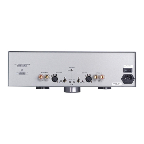
BACK PANEL CONNECTIONS
]E Remote trigger output.
]F RS232 control connection.
]G Left unbalanced input (RCA).
]H Left balanced input (XLR).
]A Right balanced input (XLR).
]B Right unbalanced input (RCA).
]C Remote trigger input.
]D XLR/RCA selector.
]I Right loudspeaker outputs (dual).
]J Mains power input and fuse.
]K Left loudspeaker outputs (dual).
RCA
XLR
-*,Ê,
,-ÓÎÓ
/,,
" ÊÊÊÊ" -*,Ê
/
*1/-
,/
*1/-
*1/-Ê-7
R> R? R@
R6 R7 R9R8 R: R; R< R=
§2 Connecting.pm7 1/12/05, 10:56 am3

>Connecting the A32 Amplifier
4
POWER CONNECTION
Connect the mains power using the enclosed mains cable.
Note: Always disconnect the amplifier and the rest of your equipment from
the mains power before connecting or disconnecting any of the cables.
OUTPUTS
Loudspeaker outputs
Connect the left and right loudspeakers to the corresponding terminals. The
terminals can accept speaker cables terminated with 4mm banana plugs,
spade terminals, or bare wires. To connect bare wires unscrew the terminal,
pass the bare wire through the hole in the terminal bolt, and clamp the wire in
place by screwing the terminal back down.
INPUTS
Connect the A32 to the preamplifier or processor using either the left and right
XLR inputs (recommended), or the left and right RCA inputs, and switch the
selector switch to the appropriate position. If you are using the XLR inputs use
high-quality balanced XLR cables. If you are using the RCA inputs use high
quality stereo RCA leads.
STANDBY MODES
The A32 provides a choice of two alternative standby modes.
After first applying power press the Standby button in the Primare logo on the
front panel to turn on the A32. After a 20 second start-up delay to allow the
amplifier to settle down the relays are turned on to connect the loudspeakers to
the amplifier outputs.
During the start-up sequence the A32 performs a self check, and if a problem
is detected the Standby indicator will flash rapidly.
To switch the amplifier to standby press the Standby button while the amplifier
is operating. This disconnects the speakers and reduces the idle current, but
leaves the circuitry operating so that the amplifier delivers optimum
performance from the moment it is next switched on.
To switch the amplifier off hold down the Standby button for more than one
second. This turns off all the amplifier circuitry for minimum power consumption
leaving only a small standby circuit running.
If you are not going to use the amplifier for a long period we recommend
turning it off, using the power switch on the back panel, to save power.
Trigger input
To power the A32 on and off remotely connect an input of at least 4V to the
left-hand TRIGGER socket on the A32, using a twin-core cable terminated in
3.5mm jack plugs. The right-hand TRIGGER socket can be used to daisy-chain
the remote output to further A30 series amplifiers.
Operating the trigger input switches the A32 on from standby, or puts it into
standby. When the trigger is connected the Standby button will only turn the
amplifier off.
§2 Connecting.pm7 1/12/05, 10:56 am4

<
Connecting the A32 Amplifier
5
RS232 PORT
The RS232 port allows the A32 firmware to be upgraded, and can be used to
control the A32 using Crestron compatible RS232 codes. For more information
contact Primare.
§2 Connecting.pm7 1/12/05, 10:56 am5

>
6
Index
B
back panel connections ............................ 3
balanced inputs .................................. 3, 4
C
connections ............................................. 3
F
fuses, replacing ....................................... ii
I
inputs................................................. 3, 4
L
loudspeakers ...................................... 3, 4
O
outputs .................................................... 4
P
power connection ............................... 3, 4
protection ................................................ 1
R
remote on/off ................................. 1, 3, 4
RS232 port ........................................ 3, 5
S
Standby button ........................................ 4
Standby indicator ............................... 1, 4
standby modes ........................................ 4
T
technical specification .............................. 2
trigger input ................................... 1, 3, 4
trigger output .......................................... 3
U
unbalanced inputs ................................... 3
X
XLR inputs ............................................... 3
§3 Index.pm 1/12/05, 10:56 am6
Other manuals for A32
2
Table of contents
Other Primare Amplifier manuals
Primare
Primare I21 User manual
Primare
Primare R32 User manual
Primare
Primare I15 User manual
Primare
Primare DAC30 User manual
Primare
Primare SP32 User manual

Primare
Primare SPA22 User manual
Primare
Primare PRE30 User manual

Primare
Primare I21 User manual
Primare
Primare A33.2 User manual
Primare
Primare A30.7 User manual
Primare
Primare Prisma i35 User manual
Primare
Primare R35 User manual

Primare
Primare PRE35 User manual
Primare
Primare A35.8 User manual

Primare
Primare A33.2 User manual
Primare
Primare A30.2 User manual
Primare
Primare SPA20 User manual
Primare
Primare I32 User manual
Primare
Primare A30.5 User manual
Primare
Primare A60 User manual
