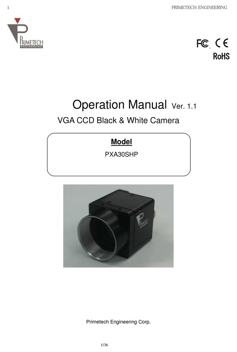
Primetech PXA30SHE User manual

1 PRIMETECH ENGINEERING
1/30
,
RoHS
Operation Manual Ver. 1.1
Analog Black & White CCD Camera
TV format
Primetech Engineering Corp.
Model
PXA30SHE (with ND filter)
PXA35SHE (no ND filter)

2 PRIMETECH ENGINEERING
2/30
I
In
nt
tr
ro
od
du
uc
ct
ti
io
on
n
Thank you for your purchase of the Primetech Engineering product.
We ensure that you will enjoy this and other products from Primetech Engineering for many years.
Keep this manual and warranty card handy for future reference.
F
Fo
or
r
S
Sa
af
fe
e
U
Us
se
e
o
of
f
t
th
he
e
P
Pr
ro
od
du
uc
ct
t
To ensure the safe use of this product, carefully read the warnings and cautions provided below prior to use:
Warning
Failure to follow the warning message may result in death or serious injury.
Caution
Failure to follow the caution message may result in injury or property damage.
W
Wa
ar
rn
ni
in
ng
g
–
–
S
Sa
af
fe
et
ty
y
P
Pr
re
ec
ca
au
ut
ti
io
on
ns
s
–
–
Never disassemble or modify the product.
Do not touch the connection cable pins or metal parts with wet hands.
Do not use the product in a place exposed to rain or water droplets or where toxic gases (liquids) are generated
nearby.
If the product will not be used for an extended period of time, unplug the connection cable from the camera.
When installing, inspecting or handling the product in a high place, implement sufficient measures beforehand to
prevent the device and parts from falling.
If you see smoke, smell a bad odor or hear an abnormal noise, immediately turn off the power supply and
unplug the cable from the product.
Do not use this product in a system that may cause a serious accident if the product exhibits an abnormality.
C
Ca
au
ut
ti
io
on
n
–
–
P
Pr
re
ec
ca
au
ut
ti
io
on
ns
s
o
on
n
U
Us
se
e
–
–
■Use the product within the operating temperature range (-5 to +45°C).
■Use the product at the specified power-supply voltage (+12 VDC).
■Avoid any strong impact or vibration to the product.
■Provide sufficient space around the installed product to prevent the product's internal temperature from rising.
■If the product is used in a dusty environment, be sure to implement dust-protection measures.
■Be sure to turn off the power supply after the cable has been unplugged and then plugged in again with the
power on.
■Dust and smudges on the surface of the cover glass will appear as black stains on the image. Blow away any
dust with air, etc., and wipe off any smudges using a cotton swab moistened with ethyl alcohol.
When cleaning smudges, be careful not to scratch the surface of the cover glass.
■It is recommended to use a daylight-color fluorescent lamp or other light source that is free from infrared light.
When using a halogen lamp or other light source containing infrared light, use an infrared cutoff filter.
■Do not share the power supply with a motor or other type of noise-generating device.
■The SG (signal ground) and FG (frame ground) are connected inside the camera. Design the system in such a
way as to prevent the looping caused by ground potential difference.
Supplemental Note
■A period of 10 to 20 minutes of aging after turning on the power allows more stable images to be captured.

3 PRIMETECH ENGINEERING
3/30
D
Di
is
sc
cl
la
ai
im
me
er
r
Primetech Engineering shall assume no responsibility for the following under any circumstance:
■Loss arising from fire, earthquake, a man-made disaster or an act of God; willful or accidental misuse of the
product; or use of the product by a third party in an abnormal manner;
■Loss arising from repair or modification performed by the customer;
■Incidental loss (lost business profit, suspension of business, etc.) arising from the use of or inability to use the
product; and
■Loss arising from malfunction, etc., caused by the combined use of connected devices.

4 PRIMETECH ENGINEERING
4/30
Revision History
Revision
Date of revision
Description of change
1.0
2019/03/14
Released the initial version.
1.1
2020/07/15
Correction of errors

5 PRIMETECH ENGINEERING
5/30
Table of Contents
1. Overview.................................................................................................................................................................................6
1.1. Characteristics................................................................................................................................................................6
2. System Configuration.............................................................................................................................................................7
3. Connection Diagram ..............................................................................................................................................................8
4. Specifications of Camera Parts .............................................................................................................................................9
4.1. Front/Top/Bottom ............................................................................................................................................................9
4.2. Rear panel.....................................................................................................................................................................10
4.3. Pin assignment for VIDEO OUT/DC IN/SYNC terminal.............................................................................................11
4.4. Input phase specifications for external VD/HD signal.................................................................................................12
4.5. WEN output specifications ...........................................................................................................................................12
4.6. Trigger pulse specifications..........................................................................................................................................12
4.7. External trigger shutter speed setting according to trigger pulse width.....................................................................13
5. Normal Shutter Mode...........................................................................................................................................................14
6. External Trigger Shutter.......................................................................................................................................................15
7. Restart/reset.........................................................................................................................................................................17
8. Timing Chart for Individual Modes.......................................................................................................................................19
8.1. Mode 1...........................................................................................................................................................................19
8.2. Mode 2...........................................................................................................................................................................25
9. Specifications........................................................................................................................................................................27
9.1. Relative spectral sensitivity characteristics.................................................................................................................28
External Dimensions....................................................................................................................................................................29

6 PRIMETECH ENGINEERING
6/30
1. Overview
This operation manual describes functions and procedures for the industrial analog camera (B/W).
1.1. Characteristics
•Diverse mode setting
The following settings can be used by toggling the switch on the rear panel.
•Gain control
•Gamma correction
•Synchronous input/output
•75 Ω termination
•Shutter function: Normal/triggered shutter
•External synchronization
Depending on a VD or HD signal input, the camera operates with external synchronization.
•Internal synchronizing signal output
Synchronizing signals (VD, HD) can be output via the 12-pin connector by toggling the switch on the rear panel.
•External triggered shutter function
A still image can be obtained by inputting a trigger. It allows stable capture of an object that moves at high speed.
•Restart/reset function
CCD images can be accumulated according to the length between VD pulses by continuously inputting synchronizing
signals (VD, HD) from an external device.
(2VD or more)
It is effective for long-time exposure.
•Camera module fixing
The screw holes for fixing the camera module are located on the lower surface of the front panel that includes the CCD
reference plane. Fixing the camera module on the front panel can minimize deviation of the optical axis.
•Complies with the new 12-pin EIAJ assignment

7 PRIMETECH ENGINEERING
7/30
2. System Configuration
<Camera module> <Camera cable> <C-mount lens>
<Tripod adaptor>

8 PRIMETECH ENGINEERING
8/30
3. Connection Diagram
C-mount lens Camera module Camera cable
<Camera adaptor, etc.>
<Tripod adaptor>

9 PRIMETECH ENGINEERING
9/30
4. Specifications of Camera Parts
4.1. Front/Top/Bottom
[1] Lens mount (C-mount)
Attach a C-mount lens or other optical equipment.
Caution
Use a C-mount lens that does not project more than 9 mm from the lens mount surface.
Be careful to select the lens to attach the camera, as the resolution of the video output from the camera may differ
depending on the lens performance. Moreover, the lens performance may vary depending on the aperture value even with
a single lens. When sufficient resolution is not attained, change the aperture value.
[2] Auxiliary screw hole for fixing camera (top)
[3] Auxiliary screw holes for fixing camera/screw holes for installing tripod (bottom)
When using a tripod, use these 4 holes to attach a tripod adaptor.
[4] Reference screw holes for fixing camera (bottom)
These holes are used to fix the camera module. Fix the camera module using these holes to minimize the deviation of
the optical axis.
Installing a tripod
Install the tripod adaptor (separately sold) onto the camera module before attaching the module to the tripod.
Use a screw that protrudes from the installation surface by 5 mm maximum (ℓ) and firmly tighten it using a hand driver.
Ensure that the protrusion never exceed 5 mm.
Caution
When installing a tripod adaptor (separately sold), be sure to use the screws provided with the adaptor.
[2] Auxiliary screw hole for fixing camera
(top)
[3] Auxiliary screw holes for fixing camera/
screw holes for installing tripod (bottom)
[4] Reference screws hole for fixing
camera (bottom)
[1] Lens mount (C-mount)

10 PRIMETECH ENGINEERING
10/30
4.2. Rear panel
Caution
Turn off the module before setting switches.
[1] VIDEO OUT/DC IN/SYNC (video output/DC power/synchronizing signal input/output) terminal (12-pin connector)
By connecting a camera cable, the +12V DC power is supplied and a video signal is output from the camera module.
When a synchronizing signal generator is connected and an external synchronizing signal (VD/HD signal) is input, the
camera module can be operated in synchronization with an external device.
[2] DIP switches for setting shutter speed and mode
•Shutter speed setting (bits 1 to 4)
Set a shutter speed suitable for shooting conditions. The factory setting for the shutter speed is OFF.
•Charge storage mode (bit 5)
The factory setting for the high-rate scanning is FRAME.
•Restart/reset/externally triggered shutter mode switch (bits 6 to 8)
The factory setting for the switch is NORMAL.
•Gamma correction ON/OFF switch (bit 9)
This switch toggles ON and OFF for Gamma correction. The factory setting is OFF.
•Gain toggle switch (bit 0)
This switch toggles MGC (manual control) and AGC (auto control) modes. The factory setting is MGC.
[3] VD/HD signal input/output toggle switch
Set the switch to the INT side to output VD/HD signals, and set it to the EXT side to input VD/HD signals from an
external device. The factory setting for the switch is the EXT side.
[4] Manual gain control knob
This knob can be used to adjust the gain when manual adjustment is selected using the gain toggle switch among the
DIP switches ([2]).
The factory setting for the knob is Mechanical Center.
Caution
When select FRAME on Charge storage mode, please adjust this control knob from Mechanical Center to MAX side. (Due
to the characteristics of CCD)
[5] 75 termination switch
Set the switch to ON for termination. The factory setting is OFF.
[2] DIP switch for setting shutter speed and mode
[1] VIDEO OUT/DC IN/SYNC
(video output/DC power/
sync signal input/output)
terminal (12-pin connector)
[5] 75Ω termination switch
[4] Manual gain control knob
[3] VD/HD signal input/output switch

11 PRIMETECH ENGINEERING
11/30
4.3. Pin assignment for VIDEO OUT/DC IN/SYNC (video output/DC power/synchronizing signal input/output) terminal
Pin assignment for VIDEO OUT/DC IN/SYNC (Video output/DC power/synchronizing signal input/output) terminal
Pin No.
Camera synchronizing
signal output
External synchronizing
signal
(VD/HD)
Restart/reset
Externally triggered
shutter
1
Ground
Ground
Ground
Ground
2
+12 VDC
+12 VDC
+12 VDC
+12 VDC
3
Video output (ground)
Video output (ground)
Video output (ground)
Video output (ground)
4
Video output (signal)
Video output (signal)
Video output (signal)
Video output (signal)
5
HD output (ground)
HD input (ground)
HD input (ground)
HD input (ground)
6
HD output (signal)
HD input (signal)
HD input (signal)
HD input (signal)
7
VD output (signal)
VD input (signal)
Reset (signal)
VD input (signal)
8
9
10
WEN output (signal)
11
Trigger pulse input
(signal)
12
VD output (ground)
VD input (ground)
Reset (ground)
VD input (ground)
Factory setting mode on the rear panel
No.
Name of switch
Factory setting mode
[1]
DIP switches for setting
shutter speed and mode
Shutter speed setting (bits 1 to 4)
OFF
Charge storage mode (bit 5)
FRAME
Restart/reset/external triggered shutter mode
switch (bits 6 to 8)
NORMAL
Gamma correction ON/OFF switch (bit 9)
OFF
Gain Binning toggle switch (bit 0)
MGC
[2]
VD/HD signal input/output toggle switch
EXT
[3]
Manual gain control knob
Mechanical Center*
[4]
75 termination switch
OFF
* When the gain toggle switch is set to MGC, the gain is variable within the range from 0 to 18 dB.
Rear panel
[1]
[4] [3] [2]

12 PRIMETECH ENGINEERING
12/30
4.4. Input phase specifications for external VD/HD signal
Set the phase relationship for external VD and HD signals as shown in the above figure.
Note that inputs other than those specified above can cause unstable internal reset.
For normal shutter mode
Continuous VD/HD signals
For restart/reset/externally triggered shutter mode
Continuous HD signal. Arbitrary timing for VD signal with the phase relationship between VD and HD within the above
specifications
4.5. WEN output specifications
Amplitude levels are representative values when the output terminates at 10 k.
4.6. Trigger pulse specifications
2 μs to 1/4 s
4to 5.0 V
0to 1.0 V
•Input impedance: 10 kor more
•Input the pulse width between 100 s and 1/4 s for DIP switch setting.
Input impedance: Enter the voltage value measured at over 10 k.

13 PRIMETECH ENGINEERING
13/30
4.7. Externally triggered shutter speed setting according to trigger pulse width
Set all DIP switches 1 to 4 on the rear panel to "0".
Setting the trigger pulse width within the range from 2 s to 250 ms will achieve an arbitrary shutter speed.
Mode 1 Mode 2
Shutter speed: trigger pulse width
Trigger pulse width + 97 sec
Caution
•DIP switch 5 is optional, but field (FL) setting is recommended. The field setting can obtain about twice the sensitivity
compared with the frame (FR) setting. next trigger is input before the video output corresponding to the latest trigger is
finished, the video is affected.
•If the next trigger is input before the video output corresponding to the latest trigger is finished, the video is affected.

14 PRIMETECH ENGINEERING
14/30
5. Normal Shutter Mode
This mode is to clearly capture high-speed moving objects with a shutter function using continuously obtained video
signals.
Setting of the DIP switches on the rear panel
1
2
3
4
5
6
7
8
9
0
1
2
3
4
5
6
7
8
9
0
1
2
3
4
5
6
7
8
9
0
1
2
3
4
5
6
7
8
9
0
1
2
3
4
5
6
7
8
9
0
OFF
1/125
1/250
1/500
1/1000
1
2
3
4
5
6
7
8
9
0
1
2
3
4
5
6
7
8
9
0
1
2
3
4
5
6
7
8
9
0
1
2
3
4
5
6
7
8
9
0
1/2000
1/4000
Flickerless
1/100
1/10000
(Units:sec)
Cautions
•DIP switch 6, 7 is optional.
•DIP switch 5 is optional, but field (FL) setting is recommended. The field setting can obtain about twice the sensitivity
compared with the frame (FR) setting.

15 PRIMETECH ENGINEERING
15/30
6. External Triggered Shutter
Inputting a trigger from an external device will enable capturing of high-speed moving objects at a correct position.
Set DIP switches 6, 7, and 8 on the rear panel to those specified for mode 1 or 2. (See the figures on the following pages.)
When the trigger pulse width is set to 1/3 s or more, the output is switched to a normal video signal.
There are two modes for the timing of obtaining videos
•Mode 1 (non-reset mode)
A video synchronous with the VD signal is output after a trigger input in this mode.
-When an external VD/HD signal is input: The video synchronizes the external VD signal.*
-When an external VD/HD signal is not input: The video synchronizes the internal VD signal.
•Mode 2 (reset mode)
In this mode, the internal VD signal is reset, and the video is output after a certain period of time has elapsed since a
trigger pulse is input.
●For individual timing charts, see pages 19 to 26.
The shutter speed can be specified by either setting the DIP switches or specifying trigger pulse widths.
●For how to specify trigger pulse widths, see page 13.
Setting with DIP switches on the rear panel
Mode 1 (non-reset mode)
1
2
3
4
5
6
7
8
9
0
1
2
3
4
5
6
7
8
9
0
1
2
3
4
5
6
7
8
9
0
1
2
3
4
5
6
7
8
9
0
1/125
1/250
1/500
1/1000
1
2
3
4
5
6
7
8
9
0
1
2
3
4
5
6
7
8
9
0
1
2
3
4
5
6
7
8
9
0
1
2
3
4
5
6
7
8
9
0
1/2000
1/4000
1/100
1/10000
(Units:sec)

16 PRIMETECH ENGINEERING
16/30
Setting with DIP switches on the rear panel
Mode 2 (Reset mode)
Cautions
•DIP switch 5, 9, 0 is optional.

17 PRIMETECH ENGINEERING
17/30
7. Restart/reset
By inputting restart/reset signals (VD/HD) from an external device, you can obtain information for one screen at an
arbitrary timing. To specify this mode, set DIP switches 6, 7, and 8 on the rear panel of the camera as shown in the
following figure.
Specifying the restart/reset function using the DIP switches on the rear panel
Long-time exposure
By extending the CCD accumulation time using the restart/reset function, you can obtain high-sensitivity images.
It is useful when sensitivity is insufficient under normal usage conditions, or to observe the tracks of a moving object.
To do this, input a VD signal that has a longer period between VD pulses (T in the figure) from an external device.
Caution
During long-time exposure, noticeable white flecks may appear.
Timing chart

18 PRIMETECH ENGINEERING
18/30

19 PRIMETECH ENGINEERING
19/30
8. Timing Chart for Individual Modes
8.1. Mode 1

20 PRIMETECH ENGINEERING
20/30
This manual suits for next models
1
Table of contents
Other Primetech Security Camera manuals
