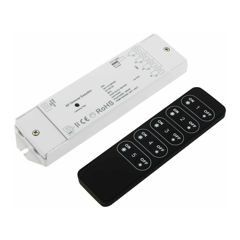
PrimeVOLT G2000 User manual

Revision History
Ver.
Date
Contents
Prepared
Approved
0.0
2019/
11/07
First released
Ted Chen
Rick Hsu

POWER LIMITER
G2000
Installation & Operation Manual
Version 0.0 Nov. 2019 Printed on Recycled Paper

1
Table of Contents
1. Safety Precautions .................................................................................................. 1
2. Contact Information ............................................................................................... 2
3. Warranty Terms ......................................................................................................3
4. Installation .............................................................................................................. 4
5. LED Indication ......................................................................................................... 9
6. Setting...................................................................................................................10
7. RS485 Communication Interface ..........................................................................12
8. Troubleshooting....................................................................................................15
9. Specifications ........................................................................................................16

1. Safety Precautions
Before beginning your journey, please read the following safety instructions
carefully.
Qualified Personnel ONLY!
Only Qualified technicians shall install or service unit(s) in
accordance with local wiring regulations.
PrimeVOLT PV Inverter ONLY!
Designed for PrimeVOLT PV inverter and solar power conversion
only; do not use for other PV inverter or conversion purposes.
Recycle
Do not throw this electronic device in a trash dumpster when
being disposed of. To minimize pollution of environment, please
consult your local service provider.

3
3. Warranty Terms
Warranty or liability will be void if damage caused by, but not limited to the
following:
1. Unauthorized opening of unit
2. Installation faults such as improper environment, wiring and applications
3. Working conditions beyond specified
4. Improper operation of unit
5. Violation of safety instructions in this manual
6. Damage during transportation
7. Any internal modifications
8. Replacing or installation of unauthorized software
9. Unforeseen calamity or force majeure

4
4. Installation
Product Overview
T/R + T/R - L3 L2 L1
+-+-+-
L3 L2 L1 N G
Product Label
O p e r a t i n g t e m p . - 2 0 ~ 5 0 o C
M a d e I n T a i w a n
Model : G2000
FA C n o m
0 . 5 A
5 0 / 6 0 H z
IA C m a x
VA C n o m 1 0 0 ~ 2 4 0 V
Front
LED
130mm
28mm
100mm
Rear

5
Unpacking
(1) Power Limiter(G2000)X 1
(2) AC Voltage Connector(6Pin)(big size) X 1
(3) AC Current Connector(6Pin)(small size) X 1
(4) RS485 Connector(2Pin) X 1
(5) User Manual
Choosing Proper Installation Site
Suitable for indoor ( temperature should not exceed 50˚C, humidity should not
exceed 95% )
Wire Connections
(1) Connecting “AC Voltage Connector” of the unpacking accessories to the “AC
Voltage Terminal”
(2) Connecting “AC Current Connector” of the unpacking accessories to the “AC
Current Terminal”
(3) Connecting “RS485 Connector” of the unpacking accessories to the “ RS485
Terminal”
(4) One limiter can connect up to 20 inverters through RS485 interface
RS485
Voltage
Current
Dip Switch
1 2 3 4
DIP
ON DIP
1 2 3 4 5 6 7 8
When the AC power is on, the LED will appear in solid green and it appears in
flashing green when RS485 communication is in normal condition. .
RS485 Connector
AC Current
Connector
AC Voltage Connector

6
Overview of Connection
(1) AC Voltage Terminal
(2) RS485 Terminal
(3) AC Current Terminal
L3 L2 L1 N G
T/R + T/R - L3 L2 L1
+-+-+-
③
①
②

7
AC Wiring Connection (Voltage Input)
1. For single-phase wiring input, the AC voltage terminals need to be connected
to L1-N.
2. For three-phase wiring input, the AC voltage terminals need to be connected
to L1/L2/L3/N.
N
L1
G
N
L1
G
N
L1
G
L2
L3
AC Wiring Connection(Current Input)
1. For single-phase wiring input, the AC current terminals need to be connected
to L1 k/l.
2. For three-phase wiring input, the AC current terminals need to be connected
to L1 k/l , L2 k/l and L3 k/l.
L1 k ( )
l ( ) L1 k ( )
l ( )
L3 k ( )
l ( )
L2 k ( )
l ( )
NOTE:1. Refer to the CT specification for the CT wiring k/l
2. (W) means white color wire, (B) means black color wire
CT Configuration
To ensure the CT ring buckle is in the correct direction before connection, please
refer to following application diagram. Choose one of the application and set
through the power limiter’s dip switch DIP7.
Single phase
Three phase
W
B
B
B
B
W
W
Three phase
Single phase
W

8
(1) Connecting CT buckle toward to grid side ①
(2) Connecting CT buckle toward to load side ②
Please follow the below configuration and make sure the direction of the CT buckle
is mainly in the direction of K->L.
T/R -
T/R +
G2000
L K
L K
Attention
In the three phases application, power limiter is ONLY applied
to 3Ø 4W power system, isn’t applied to 3Ø 3W power system.
Choose one position
of the CT application
CT ①
CT ②
Grid
Load
RS485 cable
Power cable
Inverter
Inverter
Inverter
RS485 Connector
RS485 Connector
RS485 Connector
Power Limiter

9
5. LED Indication
The LED on the power limiter left side will show the power limiter operation status
by different colors. In normal operation, the LED appears in green color. It
appears in red color when the current flow is from the load side to the grid side.
LED light sequence from left to right side definition is as follow :
Color
Indication
Power on and inverter RS485 connection
L1 current flow
L2 current flow
L3 current flow
LED light status definition is as follow :
Status
Indication
Power limiter is disconnected to AC.
Solid Green: Power limiter is power ON.
Flashing Green: RS485 connection with inverter is in normal
Solid Red: Current flow to grid

10
6. Setting
1 2 3 4
ON DIP
1 2 3 4 5 6 7 8
The relevant setting parameters and functions can be set through the dip switch of
power limiter which are including the firmware CT ratio, CT position and
communication mode.
Firmware CT ratio
Item
DIP4
DIP5
DIP6
CT Ratio
Max. Current
(R.M.S)(A)
1
OFF
OFF
OFF
1000:1
50
2
ON
OFF
OFF
2000:1
100
3
OFF
ON
OFF
2500:1
125
4
ON
ON
OFF
3000:1
150
5
OFF
OFF
ON
4000:1
200
6
ON
OFF
ON
5000:1
250
7
OFF
ON
ON
6000:1
300
8
ON
ON
ON
10000:1
500
To adjust the switch ON or OFF for dip switch pin 4~6, it depends on the CT
specification and please refer above table to adjust the ON or OFF selection of
each pin of 4~6.
NOTE:Please pay attention that the power limiter will fail to achieve the power
limitation to the gridif the dip 4~6 setting are presenting incorrect ON / OFF.
CT position
Item
DIP7
Limiter Mode
1
OFF
CT on the grid side
2
ON
CT on the load side
If dip switch DIP7 is OFF, it indicates that the CT position is on the grid side.
If dip switch DIP7 is ON, it indicates that the CT position is on the load side.

11
Communication Mode
Item
DIP8
Communication Mode
1
OFF
Host
2
ON
Device
If dip switch DIP8 is OFF, it indicates that the power limiter is in Host
communication mode.
If dip switch DIP8 is ON, it indicates that the power limiter is in Device
communication mode.

12
7. RS485 Communication Interface
About RS485
A typical RS485 connection is as below.
Some Noteworthy Points:
1. Wires between devices and computer shall be twisted.
2. Maximum allowable wire length is 1000 meters.
3. The terminal-end device should have a terminal resistor.
4. Due to multiple connections, each individual device should be assigned an
IP address as to send/receive.
RS485 Hardware Interface
T/R + T/R -
L3 L2 L1
+-+-+-
Connecting to device or computer with RS485 interface
Terminal
Resistor
Device 1
Device 2
Device N
T/R -
T/R +
T/R +
T/R -
RS485 wiring
illustration

13
Wiring Diagram
T/R -
T/R +
G2000
Pin:Off Pin:Off Pin:On
ON
1
ON
1
ON
1
1. Connecting T/R1+ and T/R1- of inverter RS485 connector to the T/R+ and
T/R- of the data logger respectively.
2. Between two inverters, connecting T/R2+ of first inverter with T/R1+ of next
inverter, and connect T/R2- of first inverter with T/R1- of next inverter.
3. Set terminal resistor switch “ON” of the terminal-end inverter (the last
inverter of the row) only. The others should be set as “OFF”.
Setting the Terminal Resistor
Each inverter has built-in terminal resistor, if RS485 is connecting to multiple
inverters or the total communication length is too long to cause the abnormal
communication, please set the terminal resistor switch to “ON” of the last inverter
in the row connection, all other remaining inverters shall switch to “OFF”.
ON Terminal Resistor is active
1 (OFF) Terminal Resistor is invalid
Inverter
RS485 Connector
Inverter
Inverter
RS485 Connector
RS485 Connector
Power Limiter

14
Attention!
Improper setting of the terminal resistor will cause
communication failure.
Use Standard RS485 Wire
In order to achieve good communication, be sure to use
standard copper mesh shielding of RS485 twisted. Do not use
general network cable as RS485 wire.
RS485 Cable AC and DC Cable Separately
To maintain good communication and reduce interference,
please separate the RS485 cables from the AC and DC wiring
and keep at least 10cm far away or use a cable with metal
shield isolation.

15
8. Troubleshooting
Please pay attention to the following matters by regularly visual check to ensure the
power limiter is operating normally.
1. Clean the dust on the power limiter.
2. Check the operation and status of the power limiter.
3. Check all wiring to confirm there is no corrosion or breakage.
4. Check all the terminals and make sure they are not loose.
Referring to below table to resolve accordingly. If the problem persists, please
contact your local service partners for further assistance.
Abnormal
Solution
LED no display
1. Check if the AC power is connected to the L1-N
position.
2. Switch off the AC power and switch on again.
LED in solid red color
1. Check if the direction of the CT buckle is on the
correct position.
2. Check if the CT +/- wiring is correct.
3. Check if the wiring of L1 / L2 / L3 voltage and
current are corresponding.
4. Check if the RS485 communication is operating
in normal (check if the green LED is flashing).
RS485 disconnection
1. Check the wiring and connector.
2. Check if the IP address of inverter is configured
correctly, and shall not duplicate the same IP
address of the other inverter.
3. Check if the last inverter in the row connection
is set terminal resistor switch “ON” , and all the
remaining inverters shall switch “OFF”.
If there is only one inverter, do not switch on
the terminal resistor.
4. Check if the cable is well twisted.
5. Keep the RS485 cable at least 10cm far away
from the AC and DC wires or use the cable with
metal shield isolation.

16
9. Specifications
Item
Unit
Specification
Input (AC)
Nominal Voltage
V
220/230/240(1Ø ),
220/380;230/400;240/415(3Ø )
Nominal Frequency
Hz
50/60
Power consumption
W
2.5
General
Operating Temperature
°C
-20 ~ 50
Ingress Protection
IP20
Protection
Class II
Humidity
%
0 ~ 95
Detection signal
Voltage Signal
1Ø (2 wire) ; 3Ø (4 wire)
Current Signal
1Ø (1); 3Ø (3)
Supporting CT Type
8 types (Refer to Firmware CT ratio)
CT Detection Position
Grid side / Load side
Communication Interface & Display
LED
Green/Red
RS485
Standard, Half-Duplex
Number of inverters
20
Mechanical
Dimension ( W x H x D)
mm
130 x 100 x 28
Weight
kg
0.32
Certification
Safety
CE
Note: Specifications are subject to change without prior notice.
Note: Power limiter contains shunt resistor. Please don’t parallel resistor or use CT
type with built-in resistor.
P/N: 614-37138-00
Table of contents

