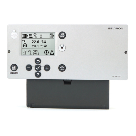
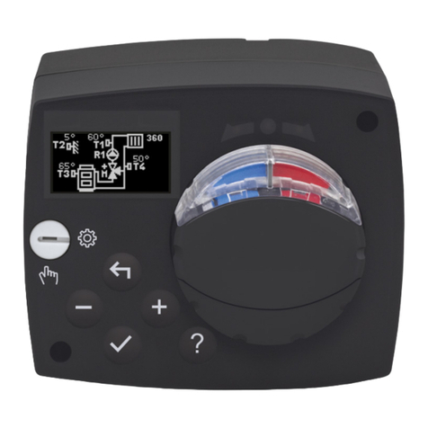
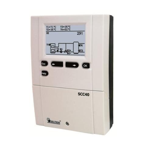
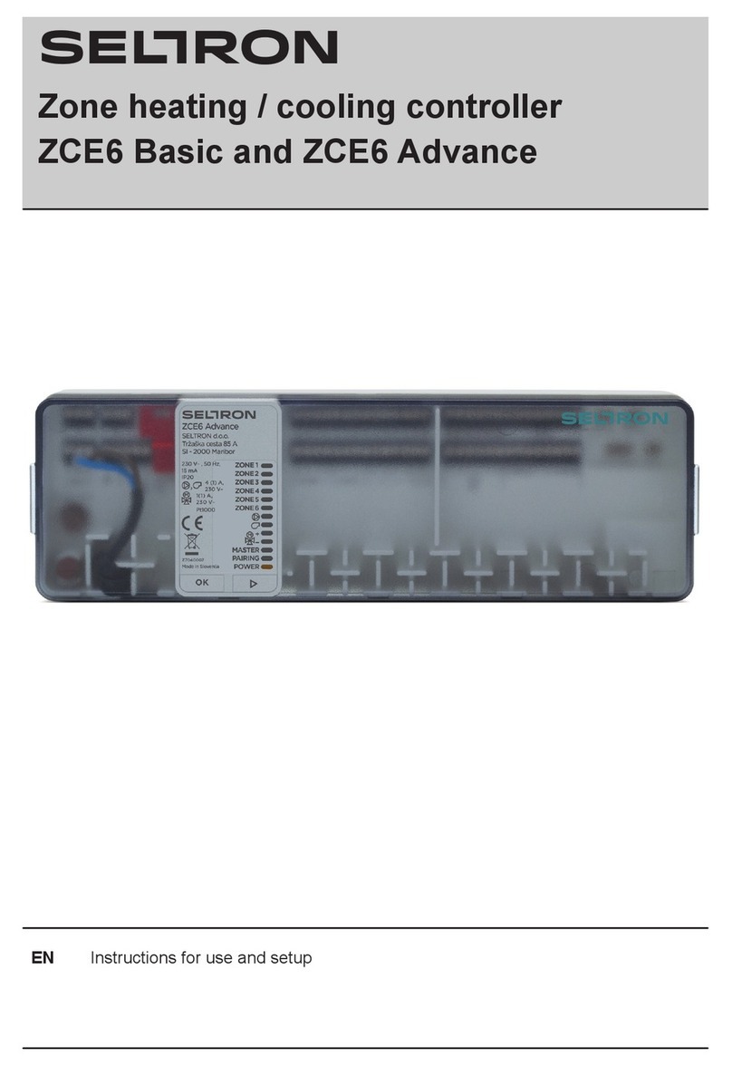
Seltron WXD10B User manual

WXD10B, WXD10, WXD20
ENG Weather compensated heating controller
Witterungsgeführter Heizungsregler
DEU


Witterungsgeführter Heizungsregler
WXD10B, WXD10, WXD20
DEU
Weather compensated heating controller
WXD10B, WXD10, WXD20
ENG


5
ENG
Weather compensated heating controller
WXD10B, WXD10, WXD20
Weather compensated controllers WXD are modern microcontroller based devices, pro-
duced in digital SMT technology.
WXD controllers are intended for boiler control of direct and/or mixing heating circuit or two
mixing heating circuits and d. h. w. warming with boiler, solar collectors and other energy
sources.
INTRODUCTION
For initial setup see Initial controller setup, page 9!

6
ENG
CONTENTS
Introduction..................................................................................................................... 5
USER MANUAL
Controller description...................................................................................................... 8
Initial controller setup...................................................................................................... 9
Keypad and other keys................................................................................................... 12
Graphic LCD display....................................................................................................... 13
Description and presentation of the basic screen: ................................................ 13
Description of symbols presented on the display ........................................................... 14
Symbols for heating circuits .................................................................................. 14
Symbols for operation mode indication ................................................................. 14
Symbols for user functions .................................................................................... 14
Symbols for indication of temperatures and other data......................................... 15
Symbols for protection functions ........................................................................... 17
Symbols for the indication of communication between devices ............................ 18
Symbols for messages and warnings.................................................................... 19
Help, messages and warnings screen............................................................................ 19
Entering and navigating through the menu..................................................................... 20
Menu structure and description ...................................................................................... 20
Temperature settings............................................................................................. 25
User functions ....................................................................................................... 26
Operation mode selection ..................................................................................... 28
Time program settings........................................................................................... 30
Basic settings ........................................................................................................ 32
Data overview........................................................................................................ 34
SERVICE SETTINGS MANUAL
Controller parameters..................................................................................................... 35
User parameters.................................................................................................... 35
Heating curve ........................................................................................................ 39
Service parameters ............................................................................................... 41
Parameters for oor drying.................................................................................... 53
default settings ...................................................................................................... 54
Mixing heating circuit............................................................................................. 55
Basic operation descriptions........................................................................................... 55
Direct heating circuit.............................................................................................. 56
Liquid fuel boiler .................................................................................................... 56
Solid fuel boiler...................................................................................................... 57
Heat accumulator .................................................................................................. 57

7
ENG
Control of the heat pump............................................................................................58
Pump for return-pipe temperature increase (bypass pump).......................................58
Domestic hot water.....................................................................................................58
Domestic hot water circulation ...................................................................................60
Remote heating activation..........................................................................................60
Operation of heating systems with two heat sources .................................................60
Setting the minimum RPM for pump R9.....................................................................63
Differential controller ..................................................................................................64
Operation modes in cases of sensor malfunction ......................................................66
INSTALLATION MANUAL
Controller installation...........................................................................................................67
Wall installation...........................................................................................................67
Panel installation ........................................................................................................68
Electric connection of the controller ...........................................................................69
Connection of temperature sensors ...........................................................................70
Room unit DD2+.........................................................................................................71
BUS connection of WXD controllers...........................................................................72
BUS connection to CMP25-2 controllers....................................................................72
Installation and connection of VT safety limiter ..........................................................73
Controller malfunction..........................................................................................................74
Sensor simulation and controller operation test .........................................................74
Controller failure and servicing...................................................................................74
Technical data......................................................................................................................75
Declaration of conformity.....................................................................................................76
Disposal of old electrical and electronic equipment.............................................................77
Notes ...................................................................................................................................78
Hydraulic schemes ............................................................................................................155

8
User manual
ENG
1 - Graphic display.
2 - USB connector for connecting personal computer.
3 - Keypad
4 - Programmable key
USER MANUAL
CONTROLLER DESCRIPTION
1
2 3 4

9
User manual
ENG
The controller requires a conrmation of language
selection with the button.
In case you chose the wrong language, return to the
language selection with the button.
INITIAL CONTROLLER SETUP
WXD heating controllers are equipped with an innovative solution “Easy start” which ena-
bles the setup of controller in just three or four easy steps.
When the controller is connected to the power supply for the rst time, the display rst
shows the program version and company logo and then the rst step of the procedure for
controller settings is started.
STEP 1 - LANGUAGE SETUP
Use buttons and to select the requested language.
Conrm the selected language by pressing .

10
User manual
ENG
STEP 2 - HYDRAULIC SCHEME SETUP
Select a hydraulic scheme for controller operation.
Move between schemes with buttons and .
Conrm the selected scheme by pressing .
The controller requires a conrmation of language
selection with the button.
In case you choose the wrong scheme, return to
scheme selection with the button.
Later you can change the selected hydraulic scheme with service parameter
S1.1.
STEP 3 - SETUP OF HEATING CURVE STEEPNESS FOR THE FIRST CIRCUIT
Set the heating curve steepness for the rst heating
circuit.
Change the value with buttons and .
Conrm the selected value by pressing .
The controller requires a conrmation of the set heat-
ing curve steepness with the button.
In case you choose the wrong heating curve steep-
ness, return to heating curve steepness selection
with the button.
Later you can change the heating curve steepness with parameter P2.1. The
meaning of heating curve steepness is detaily described on page 36.
All schemes with mixing heating circuit
are available for radiators and oor/
wall heating.

11
User manual
ENG
RESET
Disconnect the controller from power supply. Press and hold the button
and connect power supply.
Attention! The controller will be reset and requires additional setting. When
the controller is reset, all of its previous settings are deleted.
STEP 4 - SETUP OF THE HEATING CURVE STEEPNESS FOR THE SECOND CIRCUIT1
Set the heating curve steepness for the second heat-
ing circuit.
Change the value with buttons and .
Conrm the selected value by pressing .
The controller requires a conrmation of the set heat-
ing curve steepness with the button.
In case you choose the wrong heating curve steep-
ness, return to heating curve steepness selection
with the button.
Later you can change the heating curve steepness with parameter P3.1. The
meaning of heating curve steepness is detaily described on page 37.
1 This setting is not available in schemes with only one heating circuit.
The rst and the second heating circuit is marked with number on hydraulic
schemes.

12
User manual
ENG
Key Description
Move to left, decreasing.
Move to right, increasing.
Menu entry, conrmation of selection.
Help.
Return back.
Programmable key
You can program the key as a shortcut to any place in the controller
menu. In the menu, nd a location where you want to program shortcut to
point at, then press and hold the button for 2 seconds.
This way the key was programmed. Saved shortcut can be called up at
any time by pressing the key.
KEYPAD AND OTHER KEYS

13
User manual
ENG
GRAPHIC LCD DISPLAY
On the LCD display we can look up all the important data for the controller operation.
DESCRIPTION AND PRESENTATION OF THE BASIC SCREEN:
Review of data on the screen:
In the middle of the screen are displayed operation mode and active user functions. To
switch between heating circuits and the screen with the hydraulic scheme review use the
button.
Temperatures, active outputs, protection functions and other data appear in the bottom
section of the screen. To review temperatures and other data, use buttons and .
The number of sensors and other data displayed on the screen depends on the selected
hydraulic scheme and controller settings.
If you wish to retrieve the requested data after using the keyboard, look for
the data with buttons and , then conrm it by pressing the button for
2 seconds.
If you press the button for 2 seconds, the temperature review will change
from a single line review into a double line review or vice versa. In the two-
line temperature review, the measured temperature appears in the rst line,
and the requested or the calculated temperature appears in the second line.
T4=45
T5=45
T6=53
T7=--- °C
T8=--- °C
T3= 55T1=20
T2=-5
R 23 501 4 6789
Active functions.
Room unit.
State of the controller‘s outputs.
Messages
and warnings.
Time and
date.
Temperatures,
protection
functions and other
data.
Measured temperatures.
Operation mode.
Heating circuit.

14
User manual
ENG
DESCRIPTION OF SYMBOLS PRESENTED ON THE DISPLAY
SYMBOLS FOR HEATING CIRCUITS
Symbol Description
Room heating.
Room cooling.
Operation according to program timer - day temperature. *
Operation according to program timer - night temperature. *
Requested day temperature operating mode.
Requested night temperature operating mode.
D. h. w. warming according to program timer - switch-on interval. *
D. h. w. warming according to program timer - switch-off interval. *
Switch off.
Permanent switch-on of d. h. w. warming.
Manual operation mode.
Emission measurement.
Symbol Description
PARTY operation mode.
ECO operation mode.
Holiday operation mode.
One-time d. h. w. warming.
Symbol Description
The rst (mixing) heating circuit.
The second (direct or mixing) heating circuit.
D. h. w. warming.
SYMBOLS FOR OPERATION MODE INDICATION
SYMBOLS FOR USER FUNCTIONS
* The number indicates the rst or the second time program.

15
User manual
ENG
SYMBOLS FOR INDICATION OF TEMPERATURES AND OTHER DATA
Symbol Description
Measured temperature.
Calculated or requested temperature.
Room temperature.*
Outdoor temperature.
Liquid fuel boiler temperature.
Solid fuel boiler temperature.
Gas boiler temperature.
Temperature of heat source obtained through BUS connection.
Combined (liquid and solid fuel) boiler temperature.
Heat source temperature - supply temperature sensor.
Stand-pipe temperature.*
Return-pipe temperature.*
Domestic hot water temperature.
Symbol Description
Anti legionella protection.
Liquid fuel boiler switched-off (blocked).
Solid fuel boiler switch-on.
Automatic switchover to summer heating mode.
Floor drying.
Operation with constant stand-pipe temperature.
Remote activation.
Boost heating.
* The number indicates the rst or the second heating circuit.

16
User manual
ENG
Symbol Description
Heat accumulator temperature.
Solar collectors temperature.
Floor temperature. *
Boiler return-pipe temperature.
Flue gas temperature.
Temperature of the area where heat pump is installed.
D. h. w. circulation pipe temperature.
Solar collectors temperature - programmable differential thermostat.
Solid fuel boiler temperature - programmable differential thermostat.
Heat accumulator temperature - programmable differential thermostat.
D. h. w. storage tank temperature - programmable differential thermo-
stat.
Bypass pump - programmable differential thermostat.
Burner.
Burner - second stage.
Bypass pump of the heating circuit (ashing means the pump will
switch-off after expiration of delay time).
R0123456789
R0123456789
Status of the controller's control outputs - relays are switched on.
Status of the controller’s control outputs - relays are switched off.
Mixing valve - closing.
Mixing valve - opening.
Change-over valve - direct circuit.
Change-over valve - d. h. w. storage tank.
D. h. w. warming pump.
Circulation pump for d. h. w.
Solar collectors pump.
Boiler bypass pump.
Boiler circulation pump.

17
User manual
ENG
Symbol Description
Heat pump.
Electric heater.
Electric heater for d. h. w.
Boiler switchover, d. h. w. switchover
Output operation according to program timer.
T1, T2, T3,...T8 Temperature measured by sensors T1, T2, T3, T4, T5, T6, T7 or T8.
TR1, TR2
TA
TQ
TD
Temperature measured by a room sensor or room unit DD2+.
Outdoor temperature, obtained through the bus connection.
Heat source temperature, obtained through the bus connection.
Calculated requested temperature for direct circuit.
D. h. w. warming is switched off due to priority of direct heating
circuit.
Heating circuit is switched off or has limited temperature due to priori-
ty of d .h. w. warming.
Circulation pump in direct heating circuit is switched off in scope of
ED control.
Limitation of stand-pipe temperature due to exceeded maximum oor
temperature.
Limitation of stand-pipe temperature due to exceeded maximum
temperature difference between stand and return-pipe i.e. exceeded
maximum power of heating circuit.
Limitation of stand-pipe temperature due to unsurpassed minimum
boiler temperature.
Rise of stand-pipe temperature due to the exceeded protection tem-
perature of heat source.
Limitation of stand-pipe temperature due to the unsurpassed heat
source return-pipe temperature.
Counter of total operating hours and fuel consumption for burner on
1st stage.
Counter of total operating hours and fuel consumption for burner on
2nd stage.
Symbol Description
Liquid fuel boiler overheating protection.
Solid fuel boiler overheating protection.
Solar collectors overheating protection.
SYMBOLS FOR PROTECTION FUNCTIONS

18
User manual
ENG
Symbol Description
Devices connected to communication port com.
Room unit DD2+ is connected. The number beside room unit indi-
cates, whether this is the rst or the second room unit.
Burner interface or Junkers/Vaillant inteface is connected.
State of the controller in bus connection.
Standalone controller - not in bus network.
The rst controller in bus network.
Intermediate controller in bus network.
The last controller in bus network.
SYMBOLS FOR THE INDICATION OF COMMUNICATION BETWEEN DEVICES
Symbol Description
Accumulator overheating protection.
D. h. w. storage tank overheating protection.
D. h. w. storage tank overheating protection - cooling directed into the
boiler.
D. h. w. storage tank overheating protection - cooling directed into the
collectors.
Frost protection - heating circuit.
Frost protection - boiler switch-on to minimum temperature.

19
User manual
ENG
Symbol Description
Message
In the event of exceeding the maximum temperature or when a
protection function is switched on, the symbol on display ashes.
When maximum temperature is no longer exceeded or when a
protection function has switched off, a turned on symbol will note the
recent event. By pressing the button, the message review screen is
retrieved.
Warning
In the event of sensor malfunction, bus network error or com connec-
tion error, the symbol on display ashes. When the error is eliminated
or is no longer present, a turned on symbol will note the recent event.
By pressing the button, the message review screen is retrieved.
SYMBOLS FOR MESSAGES AND WARNINGS
HELP, MESSAGES AND WARNINGS SCREEN
By pressing the button, the help, messages and warnings screen is retrieved. A new
window opens with the following icons:
Short instructions
Short instructions on the use of controller.
Controller version
Review of the controller type and program version.
Messages
List of exceeded maximum temperatures and list of activated protection func-
tions. By pressing the buttons and navigate through the list of messages.
Exit the list by pressing the button.
Warnings
List of sensors and other component malfunctions.
By pressing the buttons and navigate through the list of messages. Exit
the list by pressing the button.
Delete list of messages and warnings
Delete list of messages, list of warnings and all unconnected sensors.
Attention: You will not be able to delete the sensors necessary for the control-
ler’s operation.

20
User manual
ENG
ENTERING AND NAVIGATING THROUGH THE MENU
To enter the menu press the button.
To navigate through the menu, use buttons and , and conrm your selection by press-
ing the button.
You can return to the previous screen by pressing .
If no button is pressed for some time, the screen illumination will be switched
off or reduced according to the setting.
MENU STRUCTURE AND DESCRIPTION
TEMPERATURES SETTING
Day temperature for circuit 1.
Night temperature for circuit 1.
Day temperature for circuit 2 *.
Night temperature for circuit 2 *.
D. h. w. temperature.
USER FUNCTIONS
USER FUNCTIONS FOR THE FIRST HEATING CIRCUIT
PARTY operation mode.
* The setting is only available in schemes with two heating circuits.
This manual suits for next models
2
Table of contents
Languages:
Other Seltron Controllers manuals
