Princess auto Drift hero User manual

ASSEMLBY INSTRUCTIONS
CAUTION
NEVER ATTEMPT TO START THIS MINI BIKE WITHOUT
READING AND UNDERSTANDING THE OWNER’S MANUAL.
THE OWNER’S MANUAL PROVIDES INFORMATION ON
SAFETY, PARTS, FUNCTIONS, PRE-RIDE INSPECTION,
STARTING AND MAINTENANCE.

REMOVAL FROM CRATE
FRONT FORK
ASSEMBLY HARDWARE
M10 STEERING BOLT
1
10mm WASKERS
2
M10 SELF-LOCK NUT
1
FRONT RACK AND
RENDER ASSEMBLY
FRONT RACK
1
FRONT FENDER
M8*20 BOLT
4
M8 NUTS
4
8mm WASHERS
2
ZIP TIES OF CABLES
ZIP TIES
2
ENGINE MOUNT BOLT
M8*30 BOLT
4
M8*20 BOLT
1
M8 NUTS
5
8mm WASHERS
1
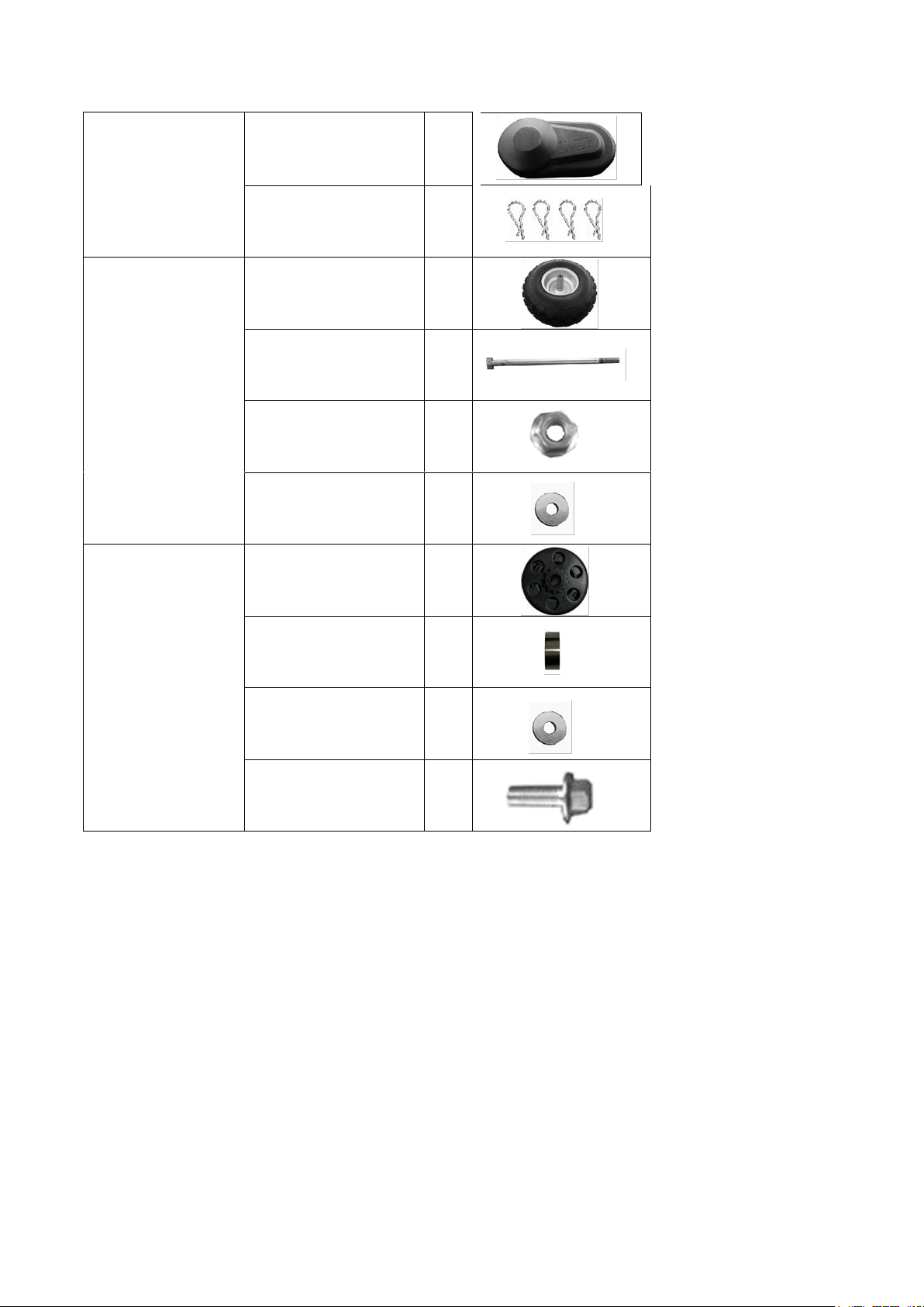
CLUTCH COVER
Clutch Cover
1
Clevis Pins
4
FRONT WHEEL
ASSEMBLY
FRONT WHEEL
1
M14 AXLE BOLT
1
M14 SELF-LOCK NUT
1
14mm WASHER
2
CLUTCH ASSEMBLY
CLUTCH ASSY
1
CLUTCH BUSHING
1
6mm WASHER
1
M5/16-24*4/3 BOLT
1

ENGINE INSTALLATION
1\ INSTALL THE JACKSHAFT ASSEMBLY TO
THE ENGINE OUTPUT SHAFT SIDE.
2\ TIGHTEN THE 4-M8*16 BOLTS:
TROUQE 13-18 ft.lbs
3\ INSTALL THE CLUTCH TO ENGINE SHAFT.
PUT THE PARTS LIKE THE FOLLOWING
ORDER:
CLUTCH BUSHING (20*25*5mm), CLUTCH ,
WASHER(8*25*3mm), M5/16-24*4/3 BOLT.
4\ TIGHTEN THE CLUTCH BOLT:
TROUQE 13-18 ft.lbs
5\ INSTALL THE CHIAN (JACKSAHFT
08MA-42) , TO CONECT THE CLUTCH AND
SECOND DRIVEN SPROKET.
Clutch Bushing
Clutch Assy
Washer and Spring washer
M5/16-24*4/3 Bolt
Engine Assembly
Drive Chian 08MA-42
4-M8*16 Bolt
Jackshft Assembly

6\ PUT THE ENINGE ON TO THE FARME, USE
THE ENGINE MOUNT BOLTS (4-M8*30 BOLT)
TO KEEP THE ENGINE ON POSITION.
7\INSTALL THE CHIAN TO SECOND DRIVE
SPROCKET, MOVE THE ENGINE FORWARD
TO KEEP THE CHAIN TIGHTED.
8\TIGHTEN THE ENGINE MOUNT BOLTS
(4-M8*30 BOLT)
TROUQE 13-18 ft.lbs
CAUTION: ALL THE PARTS ARE PUT IN THE
PAG WITH THE LABEL “CLUTCH ASSEMBLY”.
Engine Mount Bolt
Engine Mount Bolt
Other manuals for Drift hero
1
Table of contents
Popular Motorcycle manuals by other brands

MV Agusta
MV Agusta Brutale 675 Workshop manual

APRILIA
APRILIA RSV MILLE - PART 1 1999 User manual content

Royal Enfield
Royal Enfield Himalayan 2018 owner's manual

SSR Motorsports
SSR Motorsports Lazer5 owner's manual

MOTO GUZZI
MOTO GUZZI 2005 Griso 1100 Use and maintenance book

KTM
KTM 85 SX 19/16 owner's manual


