Principal LED STREET WRAP User manual

P-LED.com
325.227.4577
STREET WRAP™
INSTALLATION GUIDE
W
warranty
5P5L
GETTING STARTED
RED
Tube
LEDs
Rain
Shield
1.69"
1.38"
Inspect the boxes for damage and check the parts against the supplied parts list.
Note: Report damaged parts or shortages immediately to prevent job slowdown /stoppage to place of
purchase.
Refer to attached provided print and conrm job measurements.
Layout your job on paper, making note of Power Supply placement. Power Supplies can be placed
at the end of runs or side by side to power allowable linear footage in each direction.
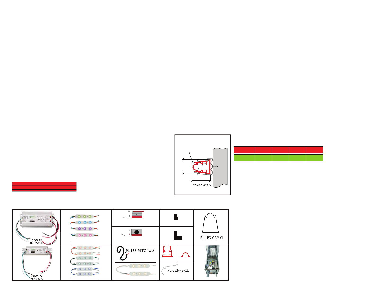
COMPONENT IDENTIFICATION & REQUIRED TOOLS
MATERIALS
Housing PVC, UC and impact resistant
Lens (LED Tube) Polypropylene, UV and impact resistant
Mounting Clip Steel
Prole Dimensions w/ Mounting Clips Street Wrap 1.38”X 1.69”
STREET WRAP™
The LEDs come pre-installed in the 106.5” System.
Same for Blue, RGB and White. Numbers are based on a 60W Power Supply.
REQUIRED TOOLS
• 25' Measuring Tape
• 100' Measuring Tape Framing Square
• Square -1’
• Portable Rechargable Drill
-5/16" hexbit and unibit
-Masonry bits (If brick wall)
• Extension Cord
• Sawzall or Compound Saw Carpenter Pencil
• Caulk Gun
• Box Knife
• Wire Strippers
• Wire Snips
• Laser Tool or Chalk Line Substitute Fasteners for the Application if Applicable
LED SPECIFICATIONS
ELECTRICAL
CONTENTS
GREEN
0.65 3.38182.522.197
0.65 3.38182.522.197
Input 12VDC
Maximum Load 60W OR 120W
Current at Max. Load 5A
Street Wrap Mounting Bracket Layout...........................................1
Installing Street Wrap into Mounting Brackets...........................2
How to Wire RGB Street Wrap............................................................3
Custom Cut to Fit End of Runs & Corners......................................4
Mounting Street Wrap on an Incline...............................................5
Frame Border Installation....................................................................6
Connecting Power Supplies...............................................................7
Testing Each Section.............................................................................8
1.
2.
3.
Note: If job measurements do not correspond to provided drawing, call Principal LED immediately at
325-227-4577. Remember: No more than 90 modules per 60W Power Supply.
Following these few simple steps will ensure a successful installation each time.
Read all instructions, before starting installation.
STREET FIGHTER RGB™
STREET FIGHTER™
STREET FIGHTER COLORS™
LED TUBE
LED TRACK
PLTC
CABLE
RAINSHIELD
COUPLING
MOUNTING
BRACKET
ENDCAP
BRACKET
WIRE HOLE CORNER PIECE
W/mod W/ft LM/ft Mod/ft
ANGLE BRACKET
QWIK BOX™
ST
S
ST
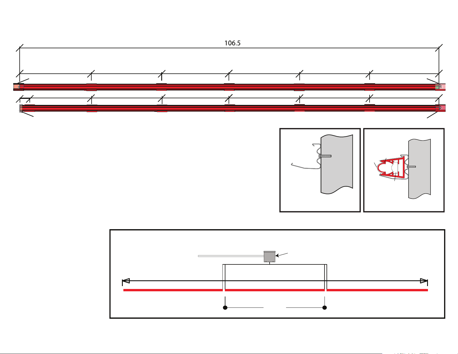
STREET WRAP™ MOUNTING BRACKET LAYOUT
3.38182.52
3.38182.52
1. Use a chalk line, gauge, laser level, or other means to be certain the run is straight, marking locations for
brackets.
Border/perimeter of sign cabinets should always have orientation of Street Fighter Wrap™ housing raised
lip outboard on vertical or diagonal. Orient brackets so that the drain holes will be on the bottom side of
the horizontal runs.
Install mounting brackets. Spacing will be no greater than 17.75”. Length for Standard, Mix-n-Match and
Specialty Street Wrap™ is 106.5”, RGB is 104”. Use pre-drilled wire hole mounting brackets at transformer
locations.
2.
3.
Install end bracket after housing
has been installed into previous
brackets by sliding over end to
ensure bracket is centered
between sections. Place mounting
brackets 3” on center from corners.
SEC. 1
Lens
LEDs
Rain
Shield
120 VAC
Note: This is correct bracket orientation.
Note: Track sections share a bracket at the ends to keep ends together and straight. There must be a space left between 106.5” plastic track sections (NOT LEDs) of 3/16”.
60W Power Supply
319.5”
106.5”
1
NOTE: MAXIMUM 3 UNITS PER 6OW POWER SUPPLY
1
TIP
END OF RUN
"
EQ.
SHARED BRACKET
3"
EQ.
SHARED BRACKET
SHARED BRACKET
EQ. EQ.EQ. EQ.
EQ. EQ.EQ. EQ.EQ. EQ.
END OF A RUN

2
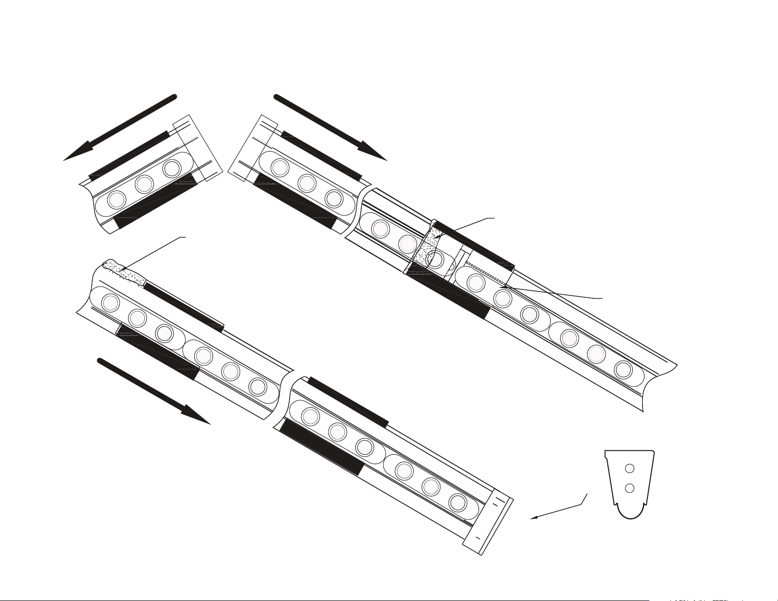
INSTALLING STREET WRAP™ INTO MOUNTING BRACKETS SEC. 2
Connect wires from one section to another using red butt splice wire connectors. No more
than 45 modules in a series.
Before hanging sections that have the power cable placed between them, cut a small notch
with dikes or other tool in the back of both housing sections to allow room for cable.
Lay the section being added on the mounting brackets. After making wire connections tuck
the wires and connectors BEHIND LED modules. Caulk notch.
Insert the top edge into the top bracket latch. Push the track housing in and roll top track
housing into mounting bracket bottom point. See Figure 1.
Bring Street Wrap™ sections close together by pushing sections together until LED modules
come together, but leave a 3/16" approximate expansion gap between plastic track sections.
Leave no gaps in the LEDs.
Install an End Cap at the beginning and end of runs with silicone. Silicone on top side only, so
water will drain out.
Finish by sliding a Coupling Rain Shield under the mounting bracket latch, over both sections.
Use a small amount of silicone on one side of rain shield to hold on.
Use a small screw driver to gently pry up the Mounting Bracket Latch to insert Rain Shield
under latch making certain it is rmly attached.
WIRE HOLE
BRACKET
NOTCH
Butt Splice Wire Connector
1.
2.
3.
4.
5.
6.
7.
8.
3/16”Approx. expansion gap
between plastic track sections
NOT LEDs.
Coupling
Rain Shield
Rain Shield
Mounting
Screw
Roll into bottom
point of track
housing
Portion Fascia
Insert top, Bracket Latch
Raised
Caulk Under
Rain Shield
Caulk Top
& Corners End Caps
DO NOT HIT LENS TO INSTALL TRACK!
This will permanently damage the lens.
Figure 1

4
CUSTOM CUT TO FIT END OF RUNS & CORNERS SEC. 4
END OF A RUN
Remove LEDs before cutting track by sliding one or two modules out.
Measure, mark and cut Street Wrap™ to required length. Use a ne blade.
Add drain holes in the center, of the cut piece of track, before reinstalling the LED.
Reinstall modules to desired length.
1.
2.
3.
4.
HORIZONTAL CORNERS
OUTSIDE CORNERS INSIDE CORNERS
Low Voltage
Cable
Track
Mounting
Bracket
Mounting
Screw
1/4" Gap for expansion
These corners are square
cut and overlap slightly
to give a continuous look
at a distance and allow
for thermal expansion.
Low Voltage
Cable
Track Mounting
Bracket
Mounting
Screw
1/4" Gap for expansion
CORNER CONNECTIONS
HINT: THREAD END CAPS ONTO PLTC CABLE FBEFORE WIRE CONNECTIONS
BACK TO BACK
PLTC CABLE
7.00”
Insulate or remove unused wires at the end of
run to prevent shorting. Do not connect wires
together or to next circuit.
VERY IMPORTANT
PLTC: Power Limited Tray Cable.
End Cap with hole drilled for
cable attach with adhesive
End Cap with hole drilled for
cable attach with adhesive
END OF A RUN
5
MOUNTING STREET WRAP™ ON AN INCLINE SEC. 5
Coupling Rain Shield
When mounting Street Wrap™ on an incline or vertically, two things
must be prevented. First the Street Wrap™ must be kept from sliding
down, while still allowing for expansion/contraction with temperature
changes. Second, water must be sealed out since it will run down the
top of the Street Wrap™.
Seal the rain shield to the upper Street Wrap™ to keep
water from penetrating.
Do NOT seal the rain shield to the lower
Street Wrap™ since the Street Wrap™ will
expand/contract.
Caulk above (or crimp) ONE
bracket towards the middle of
each of the rest of the Street
Wrap™ to prevent it from sliding
while still allowing it to expand
and contract.
Drill 2 holes in the
end cap to allow
water to escape.
6
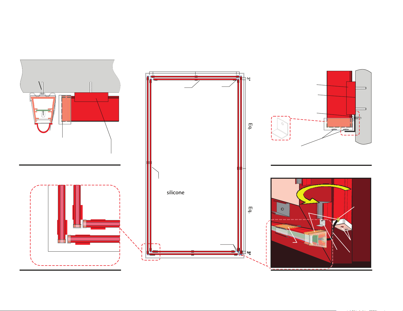
FRAME BORDER INSTALLATION SEC. 6
EXAMPLE: 104” x 196”
V-Notch
Caulk Under
Rain Shield
End Cap
& Notch
Use a screwdriver
if needed to insert
rain shield into the
bracket.
PL TC
Cable
Drain
Holes
Angle
Bracket
Add Drain Holes
on bottom of
Vertical Runs
End Cap
attach with
caulk Track
Mounting
Bracket
1/4" Gap for
expansion
Drain Holes
Low Voltage Cable
Cable Hole
Mounting Bracket
Angle Brackets
below vertical runs
to prevent sliding
Mounting
Screw
3 Brackets Per Street Wrap
BOTTOM RIGHT DETAIL, PROFILE VIEWBOTTOM LEFT DETAIL
TOP LEFT, TOP VIEW DETAIL BOTTOM RIGHT DETAIL, SIDE VIEW
Silicone
1/4" Gap Typ. for expansion
Eq. Eq.
3"3"
Always seal
drain holes
with
on verticals
when present.
Always ensure
drain holes are
on bottom side.
Add holes to the
center of a run
less than 8 feet.
End caps
attach with
Silicone.
7
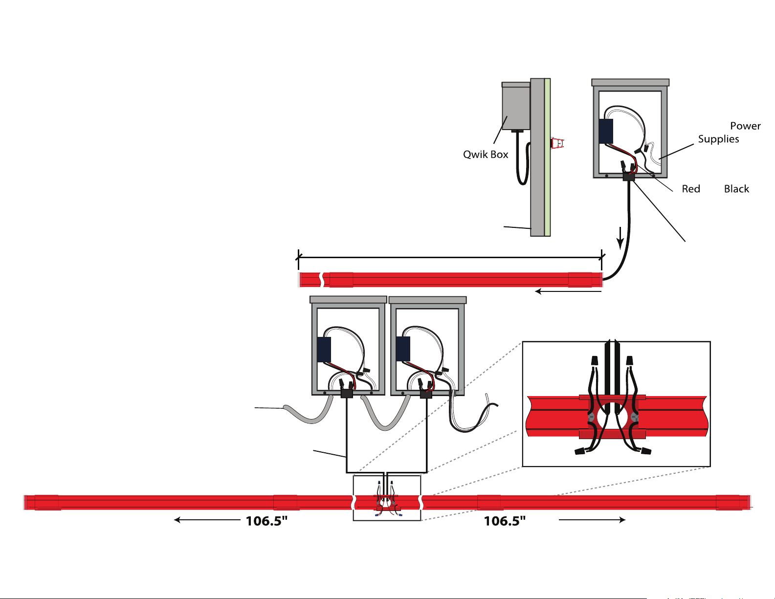
CONNECTING TRANSFORMERS SEC. 7
Attach Qwik Boxes to available support member.
Attach power supplies inside of Qwik Boxes.
Install strain relief for low voltage wire.
Drill 1/2” hole through the fascia. A conduit tting can be installed so that conduit can be
used.
Insert low voltage wire into the hole and connect to LED. Fill hole with silicone sealant.
Note: Stop and make sure the supplied power supply is 277VAC rated
with any primary voltage supply greater than 120.
1.
2.
3.
4.
5.
Note: Three 106.5”Street Wrap™ Border per 60W
Power Supply.
Side by side mounting location show below can
reduce primary and secondary wiring labor time.
VERY IMPORTANT: KEEP LOW VOLTAGE CIRCUITS ELECTRICALLY SEPARATE, DO NOT CONNECT TRANSFORMERS OR LEDs FROM
DIFFERENT 106.5” STREET WRAPS™ TOGETHER OR CONNECT MORE THAN THREE 106.5”STREET WRAPS™ TO A 60W POWER SUPPLY!
Primary 120VAC (IN)
Secondary 12VDC
Low Voltage (OUT)
Connect
Black and White
wires from
to120VAC
Connect
and
Low Voltage
wires from
Transformers
TO LEDS
Power Cable
Strain Relief
Fitting
Fascia
DO NOT
CONNECT 120
VOLTS TO LEDs.
LEDs ARE
12VDC ONLY!
12VDC
Low
Voltage
to LEDs

8
TESTING EACH SECTION SEC. 8
IMPORTANT: DO NOT SKIP THIS STEP. ALWAYS CHECK ALL LED LIGHTS BEFORE CONTINUING.
DO NOT APPLY 120V TO THE RED OR BLACK WIRES OR DIRECTLY TO THE LED MODULES.
Using the installed trasformers, supply power to the LED light chains by connecting a temporary 120V connection to
the black and white wires on the transformer to power the LED lights.
REMEMBER: BLACK AND WHITE WIRES ARE FOR 120V POWER IN, RED AND BLACK ARE FOR LOW-VOLTAGE POWER OUT.
1.
3.
2. Check to see if all LEDs are lit and working correctly.
If a module or section does not light up, is damaged, etc. —disconnect power and check connections or replace a
module by splicing in another.

P-LED.com
325.227.4577
REV20190806
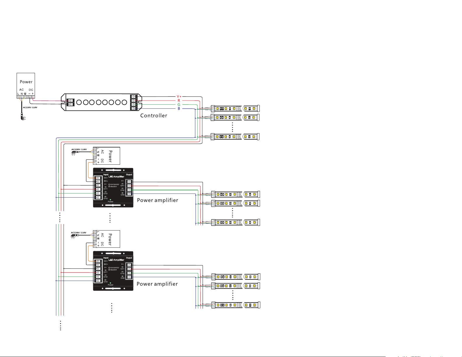
HOW TO WIRE RGB STREET WRAP SEC. 3
POWER AMPLIFIER FIGURE
NOTE: For RGB, use a maximum of 84 mods (three 104” units)/60W PS).
Watch our RGB installation and troubleshooting videos at YouTube.com/PLEDSanAngelo:
How to Wire in the 60W and 120W into the T35A Control System with Ampliers
How to Program the T3M Remote with the T35A RGB Controller 3
Other manuals for STREET WRAP
1
Table of contents
Other Principal LED Lantern manuals


Popular Lantern manuals by other brands

Gainsborough
Gainsborough K331 Assembly instructions

Gardco
Gardco ECOFORM GEN. 2 installation instructions

Gardenic
Gardenic OZ-040138 user manual

KILLARK
KILLARK KF1L SERIES Installation operation & maintenance

Tracon Electric
Tracon Electric STLCAMP10W user manual

JONATHAN Y
JONATHAN Y JYL5037A quick start guide


