Prism Hardscapes PH Ignite Operation and maintenance manual


WARNING!THISAPPLIANCEISFOROUTDOORUSEONLY!
Thismanualshouldremainwiththehomeownerorpartiesresponsibleforoperation.
TableofContents
Section1GeneralDescription
1.1SystemOverview
1.2ProductContents
1.3ProductDimensions
Section2SafetyInstructions
Section3InstallationDetails
3.1GasRequirements
3.2InitialSet‐Up
3.3WiringDiagram
3.4Installation
Section4Operation
4.1Media
4.2Operation
Section5Troubleshooting
Section6Warranty
DONOTDISCARDINSTRUCTIONS

Section1GeneralDescription
1.1SystemOverview
ElectronicIgnitionforfast&convenientfirefeaturelighting
Electronicflamesensingforinstantflamesafety&monitoring
ThisproductisdesignedandassembledtocomplywithANSIZ21‐97
Operateson12VoltsACandcomplieswithNEC2014Article680
Thisproductmaybeinstalledwithin5feetofpoolwater
Operateswithahotsurfaceignitionsystemwithrobustconstructionandreliableignitionsource
Pottedelectronicsformoistureresistanceandreliableoperation
Pilotburnerwiresaremadeofhightemperaturematerialtowithstandtemperaturesupto450
degreescentigrade(UL5335/5107)
InternalelectronicsareCSACertifiedtoZ21.20‐2014
Operatingtemperaturesarebetween‐20Fto185F
Weatherproofstainless‐steelconstructionwithwaterproofconnectors
1.2ProductContents
PARTNAMEQTY
BURNER&BURNERPLATE1
PILOTASSEMBLY(PILOTBURNER,IGNITOR,SENSORHOOD)1
IGNITIONCONTROLBOX1
HEATSHIELD 1
HEATSHIELDJAMNUT 1
ORIFICESET(BURNER&PILOT)1
TRANSFORMER(120VAC/12VAC)1
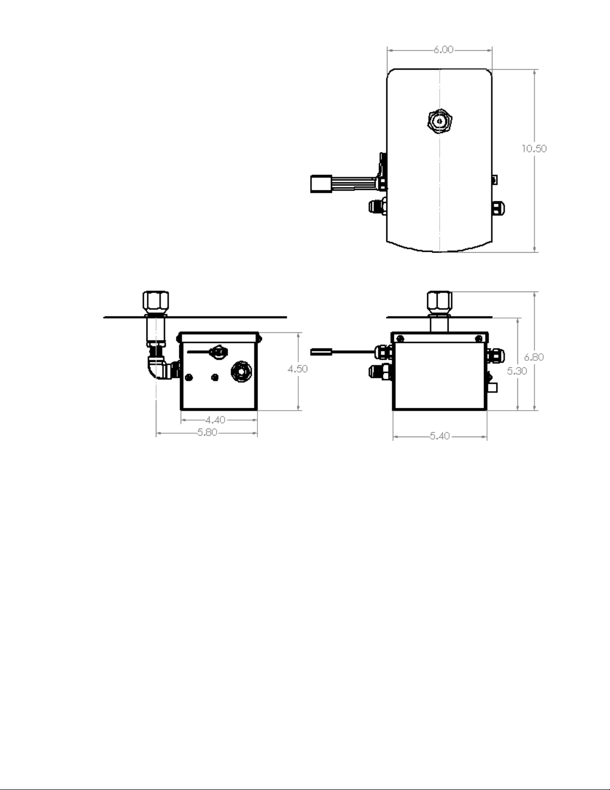
1.3ProductDimensions
Allmeasurementsininches

Section2SafetyInstructions
WARNING
Beforeinstallingthisproduct,readandfollowallwarningnoticesandinstructionsprovided.Failuretodoso
mayresultinseriousinjury,propertydamageand/ordeath.
Foradditionalfreecopiesoftheseinstructions,visitourwebsiteatprismhardscapes.com
DANGER:ELECTRICALSHOCKORELECTROCUTION
ThisproductmustbeinstalledbyalicensedorcertifiedelectricianinaccordancewiththeNationalElectrical
Code®andapplicablelocalcodesandordinances.InCanada,theCanadianElectricalCodeandallapplicable
localcodesandordinancesmustbeadheredto.Improperinstallationwillcreateanelectricalhazard,which
couldresultininjury,propertydamage,and/ordeath.
Thisproductisonlyavailablefor12‐voltACpower.Forsupplyconnections,useonlyanisolatinglowvoltage
powersupplywithungroundedoutputevaluatedandlistedbyanationallyrecognizedtestinglaboratory.
Thisproductmustbeinstalledandservicedbyacontractororqualifiedinstallerwhoislicensedand/or
certifiedwithinthejurisdictionwheretheproductwillreside.Intheeventnosuchstateorlocal
requirementexists,theinstallerormaintainermustbeaqualifiedprofessionalwithsufficientexperience
ininstallationandmaintenanceofgasappliances.Priortoinstallation,readandfollowallwarning
noticesandinstructionsthatprovidedwiththisproduct.Failuretodosomayresultinpropertydamage,
personalinjury,and/ordeath.Improperinstallationand/oroperationmayresultinexposuretocarbon
monoxideandfluegaseswhichcancauseseriousinjury,propertydamage,and/ordeath.For
installationsinthevicinityofoccupied/livingareas,PrismHardscapesstronglyrecommendsinstallation
ofcarbonmonoxidedetectorswithinreachofthisapplianceandinanyadjacentoccupiedspaces.
Im
p
ro
p
erinstallationand/oro
p
erationwillvoidwarrant
y
.
Donotstoreorusegasolineorotherflammablevaporsandliquids
withinthevicinityofthisoranyotherappliance.
WHATTODOIFYOUSMELLGAS
•
Immediatelyswitchoffmaingassupply.
•
Donottrytolightanyappliance.
•
Donottouchanyelectricalswitch;donotuseanyphonenearunit
•
Immediatelyremoveyourselffromthearea,callyourgassupplierandfollow
theirinstructions.
•
Ifyoucannotreachyourgassupplier,callthefiredepartment.
Installationandservicemustbeperformedbyaqualifiedinstaller,serviceagency
orgassupplier.

WARNING
Theappliance/systemmayproducecarbonmonoxidewhichhasnoodor.Usingthisappliance/systeminan
enclosedspacesuchasamotorhome,camper,carorhomemayresultindeath.
PrismHardscapesutilizesCSAcertifiedcomponents.Installationmustconformtolocalcodes,NationalFuel
GasCodeANSIZ223.1/NFPAand/orNationalFuelGasCode.
ApplianceshouldbeservicedannuallybyaprofessionalgastechniciancertifiedintheUnitedStatesbythe
NationalFireplaceInstitute(NFI).Anypartsthatrequirereplacementshouldbereplacedonlybyacertified
serviceprofessionalusingpartsrecommendedbymanufacturer.
Donotalteranycomponentordesignofthisunitasitmayaltertheoperation.
Firefeatureisnotintendedforcooking.Donotplaceanythingonorinfirefeature.
Neverusefirefeatureinwindyconditions.
Donotreachacrossortouchhotsurfacesoropenflames.
Donotignitefirefeaturewhenmedia(rocks/glass)iswet.Doingsomaycausemediatocrackandburst.
Itisimportanttoinspectthefirefeaturebeforeeveryuse.Makesuretherearenoobstructionsor
combustiblematerialsonornearunit.
Wipedownfirefeaturesurfacebeforeeveryuseandimmediatelycleananyspillsormessesonoraroundit.
Consistentlycheckhosesandfittingsforcracks,abrasionsandleaks(atleastonceamonth).
Alwayskeepchildrenandanimalsawayfromfirefeature.
Useadesignatedfirepitorbarbecuecoverwhennotinuse.
CALIFORNIAPROPOSITION65
ThisproductcanexposeyoutoChromium,whichisknowninthestateofCalifornia
tocausecancer,birthdefectsorotherreproductiveharm.
(formoreinformation,goto:www.p65warnings.ca.gov)

Section3InstallationDetail
3.1 GasRequirements
Ifthisitemwaspurchasedwithafirefeature,itshouldbeinstalleduponarrival.Allhardwarewillneed
tobecheckedforpropertightnessaftertransportation.Refertothecorrespondingsectionbelowfor
set‐uponyourunit.Allfirefeaturesmusthaveclearancetocombustiblesurfaceof4ftonsides&6ft
fromthetop.Refertothesectionsbelowaccordingtothegastypeused.
3.2 InitialSet‐Up
Allgasset‐upandinstallationshouldbedonebyalicensedgasprofessional.
Allelectrical/wiringset‐upandinstallationshouldbedonebyalicensedelectrician/contractor.
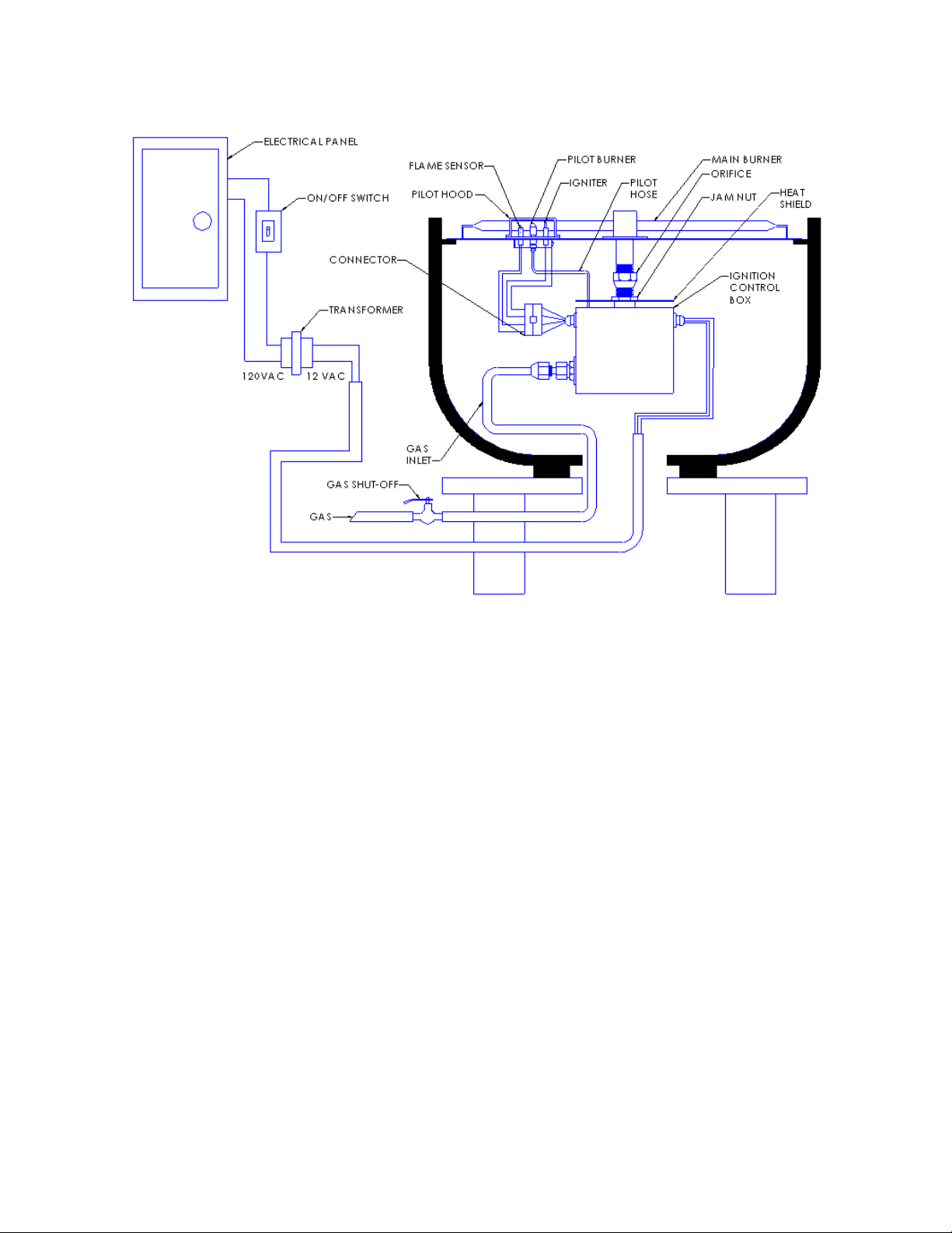
Thefirefeaturewillrequirebothgasandelectricalpower.Makesuregasandelectricityisturnedoff
beforeinstallingpipesandwires.InstallthecontrolpanelandgaspipingasshowninFigure1:Natural
Gas,Figure2:PropaneGas.
Note:Pipingandfirebowl/firepitconstructionisdifferentfornaturalgasandpropanegas.Internalgas
linesmustbecleanandfreefromanydirt,debris,orcontamination.
1. Thegaspipingandelectricalconduitmustbeinstalledundergroundbetweenthecontrol
panel/gasmeterandthefirefeature.Pleaseconsultwithagasprofessionalforpropergaspipe
andfittingsizing.Usingsmallerpipingoverlonglengthswillresultinadiminishedflamedueto
pressuredrop/pipingresistance.
2. Maintaingoodpipingpracticebykeepingpipelengthandelbowstoaminimumtoeliminate
unnecessarypressuredrops.IMPORTANT:Corrugatedflexgaslinesshouldnotbeused
undergroundaspermanentpiping.Rigidpipeshouldalwaysbeusedforpermanentinstallation.
3. Thegaspipingmustbereducedto3/4″pipeatthefirefeaturewiththemeanstoshutoffthe
gassupplyfromthegasmeter.
4. Installa3/4″to1/2”reduceratthefirefeature“stub‐out”riser.Thegasandelectricrisers
shouldnotbemorethat3”to4”abovetheinstallationsurface.
5. Installthe1/2”flareto1/2”NPTfittingintothereducerfitting/pipe.Youmayplaceamanual
shutoffvalvebetweentheelbowandthereducerforfuturemaintenance.Testgaspipingfor
leaks.
Note:Thegasandelectricalconnectionshouldbelocatedatornearthecenterofeachfirebowl/table.
Fortheelectrical,youwillneed2wiresandagroundtotheappliance.
6. Installwiring(14or16ga.)undergroundbetweenthecontrolpanelandtheburnerassembly.DO
NOTUSEBELLORSPRINKLERWIRE.Lowergaugewireisnotcapableofcarryingthecurrent
neededtooperatetheappliance.FollowthewiringdiagraminSection3.3.Theapplianceshould
bewiredtoaswitchordrycontactonthe120VACsideofthetransformer.

NOTE:Alightswitch,emergencyswitch,relaycontact,mechanicaltimershouldalwaysbeinstalledon
the120VACsideofthetransformerinordertooperatethefirefeature.The12VACsidemaybewired
asfaras150feetawayfromthetransformerusing14‐gaugewire.
7. Onlyplaceyourfirefeatureonalevelsurfaceandensurepipingiscentered,anchorifnot
directlyontheground.
8. Takethe1/2”flexhose(provided)andtightentotheflarefittingfromthesupplyline.Donot
kinkormakeatightradiusbendonthegashoseasitmayrestricttheflowofgas.
9. Thereareseveralventsanddrainageholesinthefirebowl/tablewhichmustnotbeblocked.The
electricalandgaspipeholeissealedsuchthatwatercannotpenetratethecopingsurfaceunder
thebowlandwillflowfreelyawayandouttotheedges.
3.3 WiringDiagram
Allgasset‐upandinstallationshouldbedonebyalicensedgasprofessional.
Allelectrical/wiringset‐upandinstallationshouldbedonebyalicensedelectrician/contractor.
3.3Installation
Allgasset‐upandinstallationshouldbedonebyalicensedgasprofessional.
Allelectrical/wiringset‐upandinstallationshouldbedonebyalicensedelectrician.
3.4Installation
1. TheBurner/panandcontrolwillneedtobeconnectedtothegasandelectricallinescomingup
fromthefirefeature.Makesureyouhavethecorrectorificesonthepilotandtheburnerinlet
forthegasyouareusing.Youmustusetheproperorificesfornaturalgasorpropanegasfor
boththepilotburnerandthemainburner.RefertoSection3.4.2fororificereplacement.
2. Connecttheflexiblegashosetotheinletflarefittingonthecontrolbox.Usingawrench,
tightenthehosetothefittingtoavoidgasleaks.Ifthisfittingisnottightenedcorrectlyitwill
leakandpotentiallyigniteandcandamagethecontrolsystem.
3. Connectthe12VACwires,fromthecontrolbox,totheelectricalwirescomingoutofthe
conduitusingwirenutstosecureconnections.Linkthecoppergroundwiretothe
ground/bondinglugonthecontrolbox.
4. Repositiontheburnerandpanontothefirefeatureandturnonthegastocheckforleaks.
3.4.1Installingacontrolboxonanon‐PrismHardscapesfirefeature
BesuretouseonlyPrismHardscapesapprovedburnerswithfirefeature/PH‐Ignitesystemas
theyhavebeenpre‐testedandratedfortheinputandgasdesignatedonthecontrolbox.

1. Theburnerplateiscutandfittedforthepilotburnerassemblyinorderforthemainburner
toigniteandoperateproperly.
2. Themainburnermusthaveaflameportdirectlyinfrontofthepilotfortheignitionsystem
tolightthemainburnerandsensetheflame.
BURNEREDGE
PILOTCUTOUT
PILOTCUTOUT
MOUNTINGHOLES
BURNERPORTHOLE
3. Priortoinstallingthecontrolbox,taketheburnerandplateandturnitupsidedown.Add
threadsealerontotheburnerpipethreadswithparticularattentiontothelastthreethreads.
4. Takethecontrolboxandinstalltheheatshieldontothepipe.Todothis,threadthebrass
pipenutontotheburnerorificeasfardownaspossible.Placetheheatshieldovertheoutlet
pipeofthecontrolboxandthreadtheorificeintotheoutletpipeuntiltight.Useawrenchon
theburnerorificetotightenfully.Aligntheheatshieldsuchthatitfullyshadesthecontrol
boxandtightenthebrasspipenutenoughsothattheheatshieldwillnotmove.
5. Now,takethecontrolboxandinstallitontotheburnerpipe,threaduntilfullytightened.
Alignboxsothatthepilotholeisexposedandaccessibletoinstallthepilotassembly.
6. Turntheburnerplaterightsideupandinsertpilotassemblyintothepancutoutwiththe
pilothoodslotsfacingtheburner.
7. Alignthetwomountingholesoverthetwoholesontheburnerplate.Usingtheself‐drilling
screws,securethepilotburnerassemblyontotheburnerplate.
PIPETHREADSEALER

8. Turntheburnerbackoverexposingthecontrolboxandpilotassemblywires.Refertothe
imagebelow,thisiswhatyourunitshouldlooklikethisfar.
9. Taketheflexiblestainlesssteelpilothoseandsecureontothe1/4”flarefittingatthecontrol
box.Makesureitistightbutdonotovertightenasitmaystripthethreads.
10. Takeeachhalfofthe4‐pinconnectorandjointhetwohalvestogether.Pushtheconnectors
firmlyuntilthelatchclicksintoplace.
11. Takethe1/2”stainlesssteelhoseandsecureontothe1/2”gasflarefittingonthecontrol
box.Theotherendshouldbeconnectedandtightenedontothe1/2”flarefittinglocatedat
thesupplypipestub‐outriser.
12. Placetheburnerandplatebackintopositiononthefirefeature.
13. Turnonthegasandtestforoperation.Itmaytakeafewtriestopurgealltheairfromthegas
line.
14. Oncetheburnerlights,turnofftheunitandletcool.
3.4.2ReplacingGasOrifice
Locatethetwoorifices,oneisatthebaseofthepilotburnerandtheotherisattheendofthemain
burner(seepicturesbelow).Eachorificeismeantforaspecifictypeoffuel;NaturalGasorLiquid
Propane.
BURNERORIFICEPILOTORIFICE
BURNERORIFICE
NATURALGAS
BURNERORIFICE
PROPANEGAS
PILOTORIFICE
1. Turnofftheelectricandgassupplytothefirefeature.
2. Removeanyfiremediathatisontopoftheburnerplate.
3. Unscrewthe2screwsholdingthepilotassemblyinplace.
4. Carefullypickuptheburnerplateandturnupsidedown.
5. Unplugthe4‐pinconnectorfromthecontrolboxtothepilotassembly.
6. Disconnecttheflexiblepilotgashosefromthecontrolbox.
7. Fromthetopoftheburnerplate,gentlypullupthepilotassemblyandremovefromtheplate.
3.4.3ReplacingthePilotOrifice
3.4.4PilotHeadAssembly
1. Disconnecttheflexiblegashosefromthepilot.Becarefulnottoputpressureontheceramic
flamesensor;damagingtheflamesensorwillrendertheflamesensorinoperable.
2. Removetheflarefittingfromthepilotassembly.
3. Removethepilotorificefromthepilotassemblyandreplacewiththenewone.
4. Hand‐tightentheorificeuntilseated.Usewrenchtosecurebutdonotover‐tighten.
5. Hand‐tightentheflarefittinguntilsnug.
6. Takeflexiblepilothoseandtightenontotheflarefitting.Oncesnug,usewrenchtotighten
thehosefitting.
PILOTHOOD
PILOTSENSOR
GROUNDWIRE
PILOTORIFICE
PILOTGASHOSE
FLAREFITTING
PILOTPLATE

3.4.5ReplacingtheBurnerOrifice
1. Turnofftheelectricandgassupplytothefirefeature.
2. Removeanyfiremediathatisontopoftheburnerplate.
3. Unscrewthe2screwsholdingthepilotassemblyinplace.
4. Carefullypickuptheburnerplateandturnitupsidedown.
5. Makesurepilotassemblyhasbeendisconnectedandremoved.
6. Usingawrench,unscrewtheburnerorificefromthepipe,keepahandunderthecontrolbox
sothatitdoesn’tfallwhentheorificedisengages.
7. Placetheremovedassemblyonaflatsurfaceandholdfirmly.
8. Usingawrench,removeburnerorificefromthecontrolboxoutletpipe.Becarefulofthe
heatshieldasitwillcomeoffoncetheorificeisremoved.
ORIFICE
JAMNUT
HEATSHIELD
OUTLETPIPE
PILOTHOSE

9. Removethejamnutfromtheorifice.
7.Placenutontotheneworificeandthreadituntilitwillnolongerturn.
8.Placepipethreadsealerontotheneworificethreadscovering,besuretocoverthelastthree
threadswell.
9.Placetheheatshieldoverthecontrolboxoutletpipeandbeginthreadingtheorificeinto
place.Tightenwithawrenchuntilsecure.
10.Oncetheorificeistightened,therewillbeseveralthreadsleftbetweenthejamnutandthe
heatshield.Withthewrench,tightenthejamnutuntiltheheatshieldisfirmlysecuredinto
place.

12.Placepipethreadsealerontotheburnerpipe.
13.Placethecontrolboxoutletontotheburnerpipeandturnclockwiseuntiltight.
14.Alignthecontrolboxtowherethepilotholeisaccessible.
PILOTHOLE

3.4.6FinalBurnerandPilotAssembly
1.Turntheburnerplaterightsideup.Insertthepilotconnectorandhosethroughthepilothole
ontheplate.Makesuretheslottedsideofthepilothoodisfacingtheburner.
2.Alignthepilotplatemountingholesandsecurethetwomountingscrewsthroughthepilot
platetotheburnerplate.
3.Turntheburnerplateupsidedown.Takethe4‐pinconnectorfromthepilotandconnectitto
thematching4pinconnectorfromthecontrolbox.Pushfirmlytomakesureitclicksinto
place.
MOUNTINGSCREWS

4.Taketheflexiblestainlesssteelpilothoseandconnectittothecontrolboxfitting.Securewith
wrenchbutbecarefulnottoover‐tightenasitmaydamagethebrassthread.
5.Attachthegassupplyflexhosetothecontrolboxgasinletfittingandsecurewithwrench.
15. Placetheburnerandplatebackintopositiononthefirefeature.
16. Turnonthegasandtestforoperation.Itmaytakeafewtriestopurgealltheairfromthegas
line.
17. Oncetheburnerlights,turnofftheunitandletcool.

Section4Operation
4.1Media
Carefullyspreadthefiremediaevenlyontotheburnerplate,donotoverfill.Youmaycovertheburner
untilitisnotvisiblebutdonotcoverthepilothood,seeimagebelow.
4.2Operation
Turnonthepowerswitchtotheunit.After3seconds,theigniterwillbegintoglowred.Thepilotburner
willthenigniteandstaylitfor6to8secondsuntilthemainburnerproducesflames.Oncetheburneris
lit,theignitorwillturnoffandtheflamesensorwillkeeptheflamesgoing.
Note:Windgustsmaydisplacetheflameawayfromtheflamesensorcausinga7secondsystemtoshut
downandre‐startthefiringsequence.Thesystemwilltry3timestolight.Ifitstillfailstoignite,itwill
lockout(turnoffcompletely)andwillneedtoberesetbyturningthepoweroffandthenonagain.
Donotoperateinrainyconditionsastheflamewillnotoperateoptimally.
Alwaysturnoffyoursystemwhenfirefeatureisnotinuseandneverleavetheunattended.
Itisrecommendedtocoveryourfirefeatureifitwillbeoutofuseforalongperiodoftime.
Table of contents


