PSR ACT Guide

C
Ca
ab
bl
le
e R
Re
ee
el
l/
/C
Ca
ab
bl
le
e/
/A
An
ng
gl
le
e/
/L
Le
en
ng
gt
th
h
R
Re
ep
pl
la
ac
ce
em
me
en
nt
t I
In
ns
st
tr
ru
uc
ct
ti
io
on
ns
s
Rev 4 6-15-05


Contents (ACT)
Cable Reel Removal Page 3-7
Cable Reel Replacement Page 8
Cable Reel Layout Page 9-10
Cable Reel Angle Adjustments Page 11-12
Cable Reel Radius Adjustments Page 13
Cable Broken repair Page 14-16
Cable Replacement Page 17-23
Cable reel angle pot replacement Page 24-25
Cable reel length pot replacement Page 26-29

Cable Reel replacement Instructions(ACT)
Fully retract the boom and lower it to zero degrees, now turn the power off the system.
Cable Reel replacement Instructions(ACT)
Disconnect the cable that comes from the swivel area of the machine at the
cable disconnect located by the slip ring collector for the cable reel.

Cable Reel replacement Instructions(ACT)
5
Disconnect the wires at the junction box for the A-2-B switch
Note:
For cable reels with two conductor cable connect the red and gray
wires for the A-2-B circuit in the boom tip junction box.
For cable reels with three conductor cable connect the red and
green wires for the A-2-B circuit in the boom tip junction box.

Cable Reel replacement Instructions(ACT)
6
CAUTION: THE CABLE REEL IS UNDER TENSION!!
DO NOT RELEASE THE CABLE AND ALLOW IT TO RETRACT ON ITS OWN.
DAMAGE CAN OCCUR TO THE GEAR ASSEMBLY.
Remove the cable clamp and rubber grommet, save it for later. Hold on to the cable and slowly release
the cable back towards the cable reel by hand to release the tension.
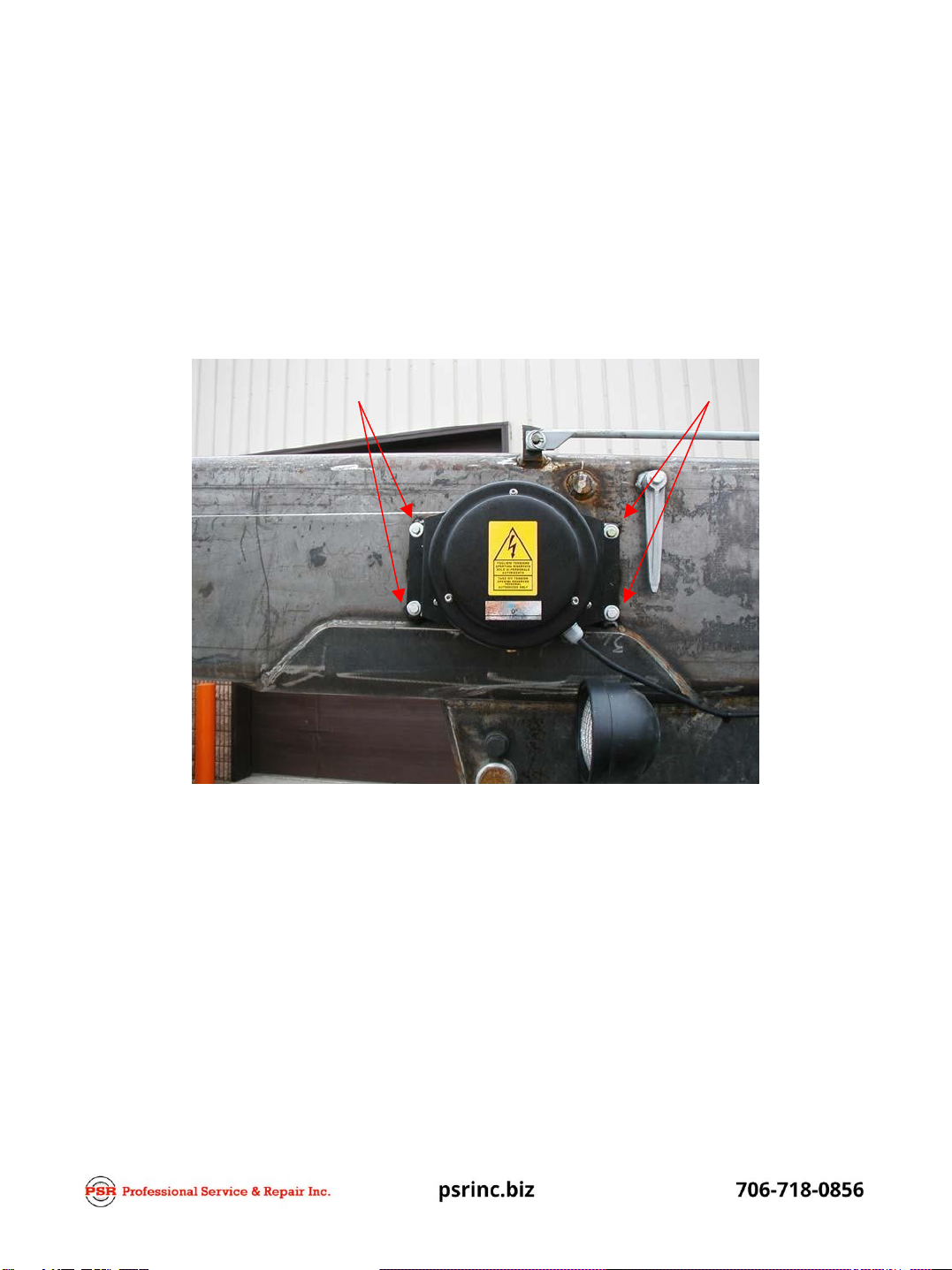
Cable Reel replacement Instructions (ACT)
Remove the four mounting bolts on the cable reel that attach it to the boom
and replace the cable reel with the replacement cable reel. Tighten the four bolts.

8
Cable Reel replacement Instructions (ACT)
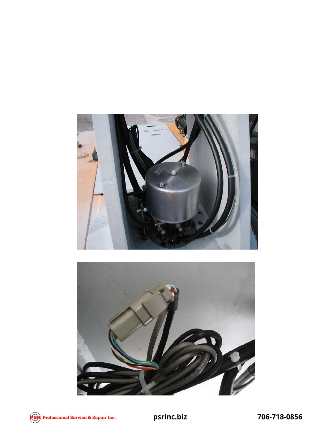
The replacement reel has a coil of excess wire and a clamp on it (Fig 1). Pull the cable out through
the roller-guides to the boom tip. Measure how much of the excess wire you need to re-connect
the wires to the junction box for the A-2-B switch and cut off the excess wire.
Attach the cable clamp and rubber grommet you removed (Fig 2) and connect the wires to the junction box.
Remove the clamp back and rubber grommet at the cable reel.
When completed you should have tension on the cable from the reel (Fig 3) in order for the reel to wind up
properly, if not readjust the cable clamp to tension it more.
Fig 1. Fig 2
Fig 3

C
CA
AB
BL
LE
E R
RE
EE
EL
L A
AC
CT
T
L
La
ay
yo
ou
ut
t
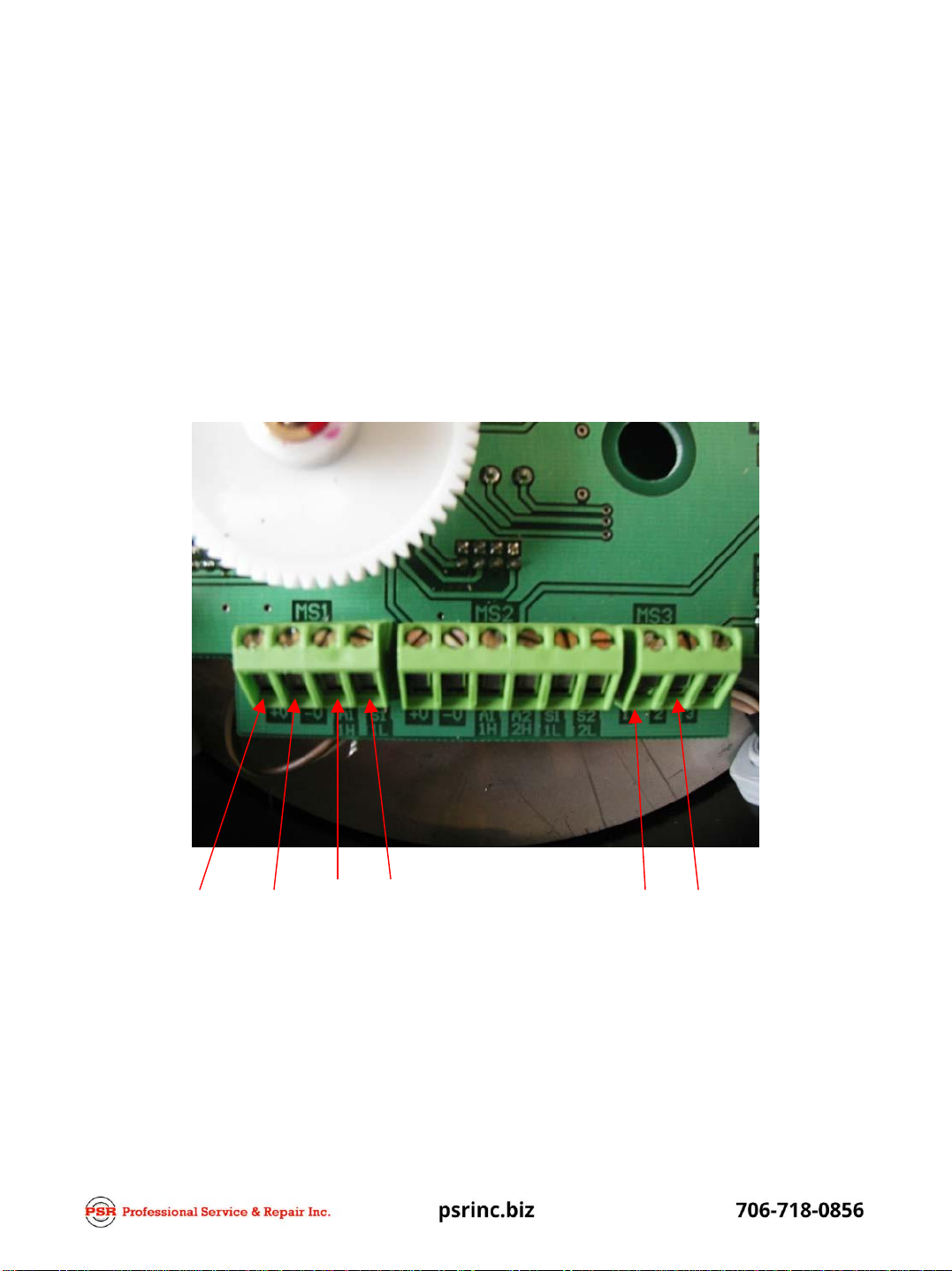
1. The reel is equipped with three separate terminal strips MS1, MS2, and MS3. MS1 and
MS3 are used.
Angle Pot is located on back side of electronic
Length Pot Assembly MS1 MS2 MS3
C
CA
AB
BL
LE
E R
RE
EE
EL
L A
AC
CT
T
L
La
ay
yo
ou
ut
t/
/W
Wi
ir
ri
in
ng
g
1. MS1
2. +V = +5vdc supply voltage for angle/length/ Green wire
3. -V = Ground/Gray wire
4. A1 = Angle output/Blue wire Zero degrees output should be +2.50vdc
5. L1 = Length output/White wire Fully retracted boom output should be +0.250vdc
+5vdc Ground
1. MS2 Not used
Angle Length A-2-B
return A-2-B
+12vdc
1. MS3
2. #1 A-2-B return/pink wire
3. #2 A-2-B +12vdc supply/red wire
4. Yellow wire is shield to be connected to the pc board mounting lug

C
CA
AB
BL
LE
E R
RE
EE
EL
L A
AC
CT
T
S
Se
et
tt
ti
in
ng
g A
An
ng
gl
le
e o
on
n c
ca
al
li
ib
br
ra
at
te
ed
d u
un
ni
it
ts
s
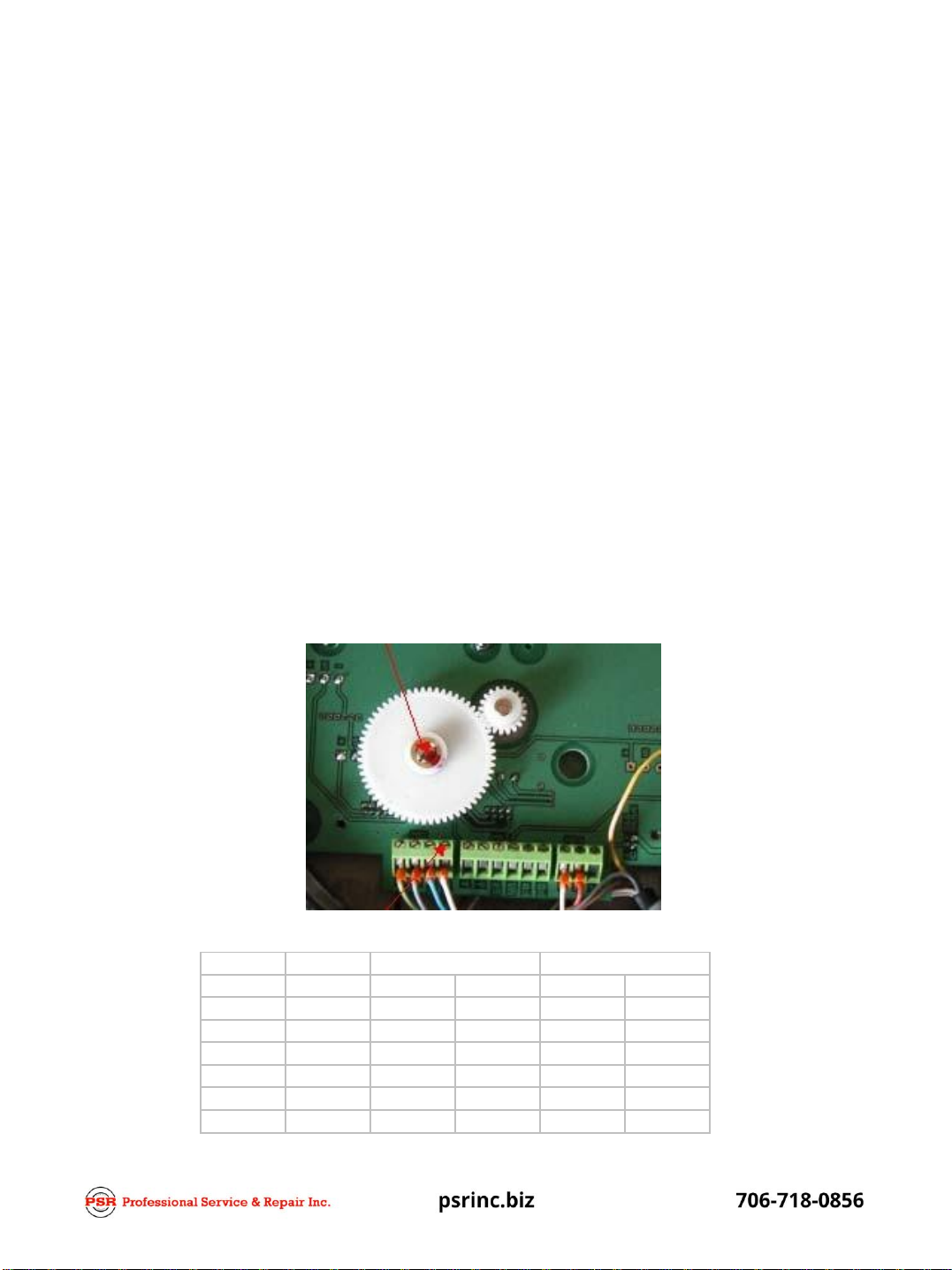
To set the angle;
Fully retract the boom, and boom the machine down to zero degrees using a level or angle
finder to determine zero degrees.. Look at the display to see what the angle indication
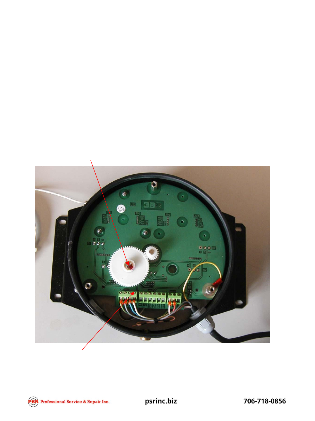
is. Remove the three mounting lugs on the pc board. See next page, Tip the pc board
out and loosen the three angle pot mounting screws. Holding the pc board as close to
vertical as possible turn the angle pot until the display indicates zero degrees. Tighten
the three angle pot screws and replace the mounting lugs on the pc board.Do not
forget to connect the shield. Check the angle indication again on the display. Adjust as
needed until it indicates zero degrees. Tighten all screws and close reel. At zero
degrees the angle output on MS1/A1 should be approximately +2.50vdc (range
+ 2.48vdc to 2.51vdc).
PC board mounting lugs
MS1/A1 Angle output

C
CA
AB
BL
LE
E R
RE
EE
EL
L A
AC
CT
T
S
Se
et
tt
ti
in
ng
g A
An
ng
gl
le
e o
on
n c
ca
al
li
ib
br
ra
at
te
ed
d u
un
ni
it
ts
s
Angle Pot
Length Pot Angle Pot screws
C
CA
AB
BL
LE
E R
RE
EE
EL
L A
AC
CT
T-
-1
1P
PA
AE
E/
/0
00
0
S
Se
et
tt
ti
in
ng
g R
Ra
ad
di
iu
us
s o
on
n c
ca
al
li
ib
br
ra
at
te
ed
d u
un
ni
it
ts
s
To set the Radius;
Fully retract the boom, and lower boom to zero degrees, look at the display to see what
the radius indication is. Using a flat tip screw driver turn the screw on the length pot
assembly until the radius indication on the display is correct. Now extend the boom fully
and check it, then retract it again to see if it is ok. Continue this procedure until the
radius indication is correct. MS1/L1 should be approximately +0.250vdc (range +
0.248vdc to 0.251vdc).
Length pot adjustment screw
MS1/L1 Length output

C
CA
AB
BL
LE
E R
RE
EE
EL
L A
AC
CT
T-
-1
1P
PA
AE
E/
/0
00
0
B
Br
ro
ok
ke
en
n C
Ca
ab
bl
le
e r
re
ep
pa
ai
ir
r
1. Check if the length assembly is damaged internal of the cable reel by physically pulling
the cable out by hand and listen for a clicking sound when pulling it out. We are
checking to see if the spring package internal of the cable reel has been damaged. If no
clicking noise is present, spring package should be ok.
2. Remove the cable reel cover and physically check for any broken components. Using a
voltage meter put the ground lead on terminal –VB (ground) and the positive lead on
terminal +VB of MS1. With power on the system it should be +5.00 vdc (range of +4.96
to +5.00vdc). If not check length pot for damage inside cable reel.
3. Check between –VB and S1 on MS1 for an output. Should be at least +0.250vdc. Pull
out some cable on the reel and check again to see if length pot is ok, voltage should
increase.
+5vdc
Ground
Length Output
C
CA
AB
BL
LE
E R
RE
EE
EL
L A
AC
CT
T-
-1
1P
PA
AE
E/
/0
00
0
B
Br
ro
ok
ke
en
n C
Ca
ab
bl
le
e r
re
ep
pa
ai
ir
r
4. If the cable was cut close to the end of the boom, there should be enough cable left on the
reel to re-connect. There shall be at least three wraps of cable left on thecable reel drum with
a fully extended boom in order to use the existingcable.
Otherwise the cable must be replaced.
5. Fully retract the boom and at zero degrees, reconnect the cable at the tip of the boomtip. The
cable should have some tension on it so the cable does not droop, buttaunt.
Turn on the power of the system and using a volt meter check the length output on S1 of
MS1 terminal on the terminal.
6. Output needs to be +0.250vdc (range +0.248 to 0.251vdc, if not using a small flat tip
screwdriver adjust the screw on the length pot until it is close. Now look to the radius read
out on the display. It should indicate the minimum radius of the machine in feet and tenths.
See below.
Boom Radius
Feet/tenths
Minimum
Maximum
IC-20-1
6.2
15.2
IC-35-2
7.5
19.6
IC-80-1
8.4
20.3
IC-80-2
9.8
24.3
IC-80-3
11.8
30.2

C
CA
AB
BL
LE
E R
RE
EE
EL
L A
AC
CT
T-
-1
1P
PA
AE
E/
/0
00
0
B
Br
ro
ok
ke
en
n C
Ca
ab
bl
le
e r
re
ep
pa
ai
ir
r
7. Boom at zero degrees and extend the boom out and check for the maximum boom
radius on the display. Fully retract the boom and check the minimum boom radius again
adjust if required until the display indicates the proper radius.
8. The boom radius is not set. The system was already calibrated, therefore we only need
to adjust the length pot at the minimum radius. The system should be checked at min
and max radius and will indicate the proper radius in all positions of extension in feet
and tenths.
9. Replace the cable reel cover and tighten hardware properly.
Boom Radius
Feet/tenths
Minimum
Maximum
IC-20-1
6.2
15.2
IC-35-2
7.5
19.6
IC-80-1
8.4
20.3
IC-80-2
9.8
24.3
IC-80-3
11.8
30.2
C
CA
AB
BL
LE
E R
RE
EE
EL
L A
AC
CT
T-
-1
1P
PA
AE
E/
/0
00
0
C
Ca
ab
bl
le
e R
Re
ep
pl
la
ac
ce
em
me
en
nt
t
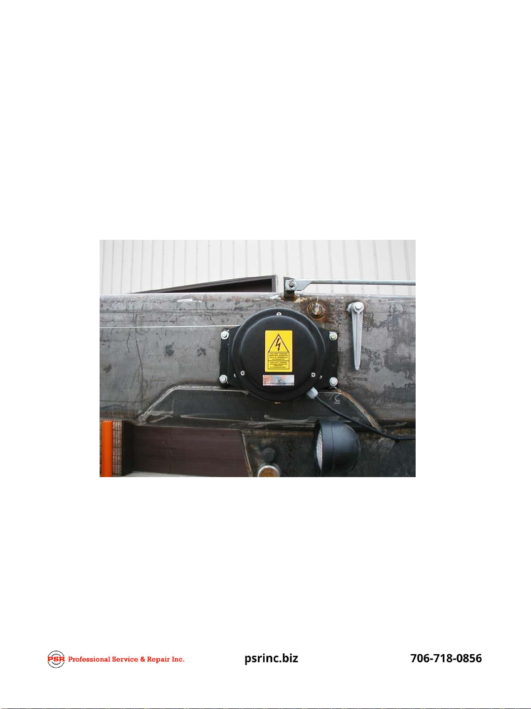
Disconnect the cable reel connector by the slip-ring collector and
remove the four mounting bolts on the cable reel and remove the reel from the machine.
Other PSR Industrial Equipment manuals

Popular Industrial Equipment manuals by other brands

Bulteh 2000
Bulteh 2000 EKOMILK mini DAIRY Plant 120L Technical manual

Eaton
Eaton Quickmov SPDQM1 Installation & specification

Nexen
Nexen Air Champ FMCBE 625 user manual

WDT
WDT DUFTDOS-DS operating instructions

Siemens
Siemens SIMATIC RTLS Applications manual

Graco
Graco SuperCat 232721 Instructions-parts list


PCB Piezotronics
PCB Piezotronics ICP 320C15 Installation and operating manual

ABB
ABB HT588340 Operation manual

ESCO Technologies
ESCO Technologies ETS-LINDGREN 1739612 quick start guide

Festo
Festo VABM-B10-25EEE manual

SCHUNK
SCHUNK JGP-P 40 Assembly and operating manual

WAMGROUP
WAMGROUP OLI MVE 60/3 manual