Table of Contents 3
© Lutz-Jesco GmbH 2020
Subject to technical changes.
200116
BA-42840-02-V03
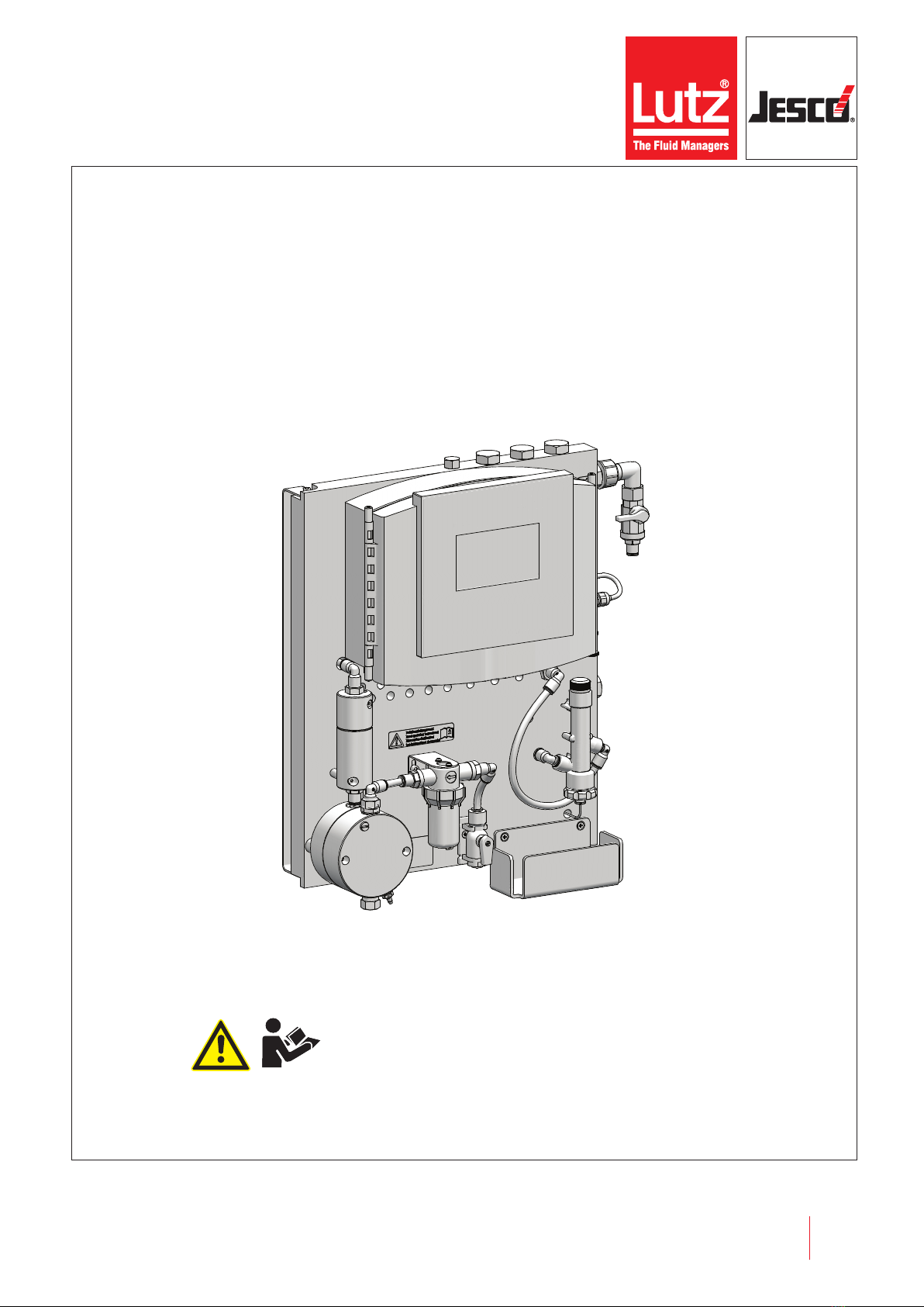
Water sampling station EASYPRO COMPACT Operating instructions
Table of Contents
1 Notes for the Reader ..........................................................4
1.1 General non-discrimination......................................................4
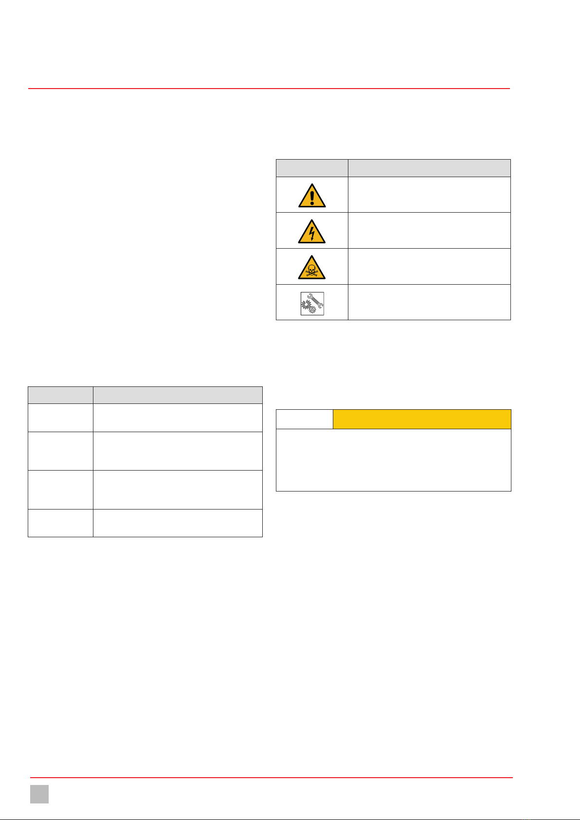
1.2 Explanation of the signal words ................................................4
1.3 Explanation of the warning signs ..............................................4
1.4 Identification of warnings.........................................................4
1.5 Identification of action instructions ...........................................4
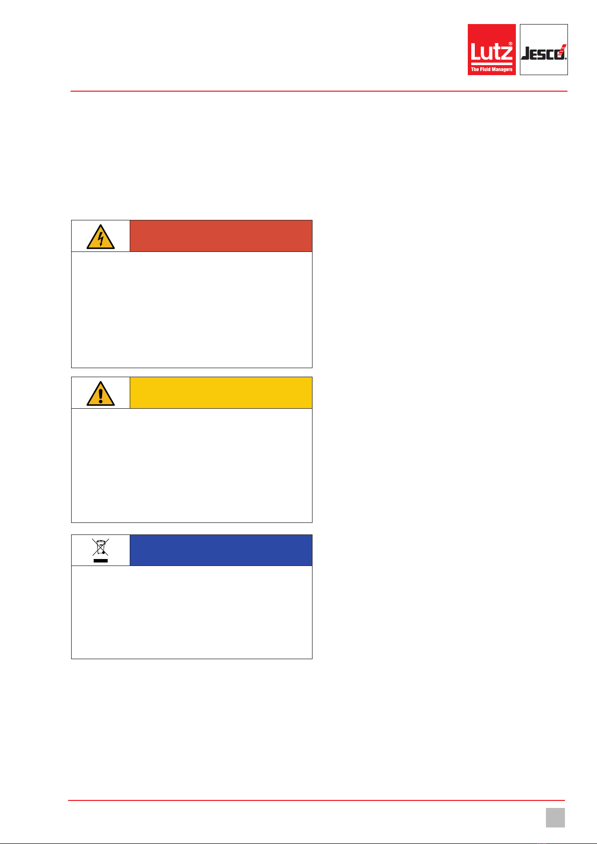
2 Safety .................................................................................5
2.1 General warnings.....................................................................5
2.2 Hazards due to non-compliance with the safety instructions .....5
2.3 Working in a safety-conscious manner .....................................5
2.4 Personnel qualification.............................................................5
3 Intended use ......................................................................7
3.1 Notes on product warranty .......................................................7
3.2 Intended purpose.....................................................................7
3.3 Foreseeable misuse.................................................................7
4 Product description ...........................................................8
4.1 Scope of delivery .....................................................................8
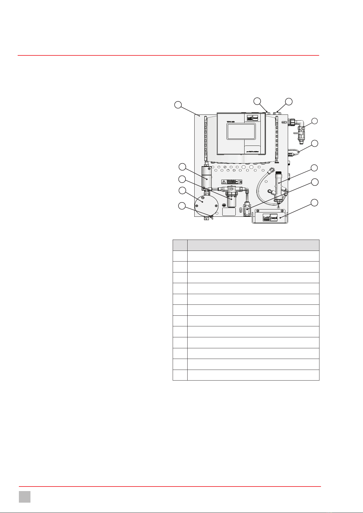
4.2 Design and function of the water sampling station ....................8
4.3 Position numbers water sampling station .................................8
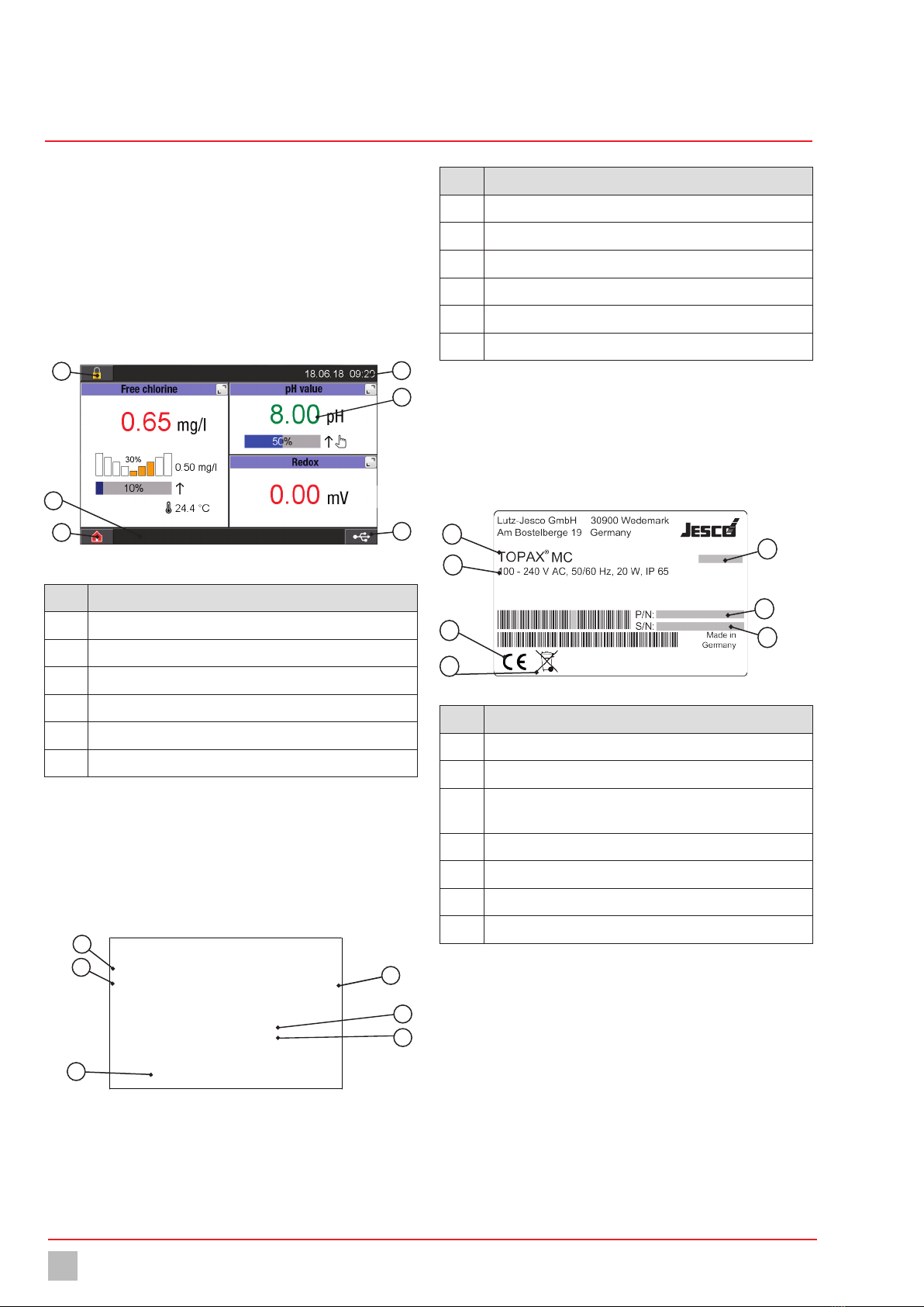
4.4 Design and function TOPAX®MC ..............................................9
4.5 Rating plate EASYPRO COMPACT water sampling station ........10
4.6 Rating plate TOPAX®MC multi-channel controller...................10
5 Technical data.................................................................. 11
5.1 Water sampling station...........................................................11
5.2 measuring cell.......................................................................12
5.3 Technical data TOPAX®MC multi-channel controller ...............12
5.4 Multi-channel controller TOPAX®MC measuring inputs...........13
5.5 Multi-channel controller TOPAX®MC output modules..............13
5.6 Terminal clips of the main board and the components .............14
6 Dimensions ......................................................................15
6.1 Water sampling station...........................................................15
6.2 Wall holder.............................................................................16
7 Installation .......................................................................17
7.1 Installation location................................................................17
7.2 Wall mounting........................................................................17
7.3 Electrical installation..............................................................17
7.4 Installing the hydraulics .........................................................18
7.5 Connecting sensors ...............................................................18
7.6 Connecting the actors ............................................................19
7.7 Digital inputs .........................................................................21
7.8 RC protection for relay............................................................21
7.9 Connecting Ethernet ..............................................................21
7.10 RS485 interface...................................................................21
8 Commissioning of the water sampling station ...............23
8.1 Setting the flow controller ......................................................23
8.2 Adjusting the measuring cells for measuring the pH and Redox
value............................................................................................23
8.3 Calibrating the disinfection measuring cell..............................23
8.4 Commissioning of TOPAX®MC multi-channel controller ..........24
8.5 First steps..............................................................................25
8.6 Configuration.........................................................................25
8.7 Password protection ..............................................................30
8.8 Network settings....................................................................31
9 Operation..........................................................................32
9.1 Confirming a message ...........................................................32
9.2 Logbook ................................................................................32
9.3 Configure trend display ..........................................................32
9.4 Manual mode.........................................................................33
9.5 Calibration.............................................................................33
9.6 Setpoints and reference sets..................................................36
9.7 Access via network ................................................................38
10 Shutdown.........................................................................39
10.1 Short-term shutdown...........................................................39
10.2 Long-term shutdown ...........................................................39
10.3 Storage ...............................................................................39
10.4 Transportation......................................................................39
10.5 Disposal ..............................................................................39
11 Maintenance ....................................................................40
11.1 Maintenance intervals..........................................................40
11.2 Measuring cells ...................................................................40
11.3 Flow controller.....................................................................40
11.4 Cleaning the sample water filter ...........................................40
11.5 Keeping logfiles ...................................................................41
11.6 Updating software................................................................41
11.7 Battery ................................................................................41
11.8 Replacing the fuse ...............................................................41
11.9 Resetting the settings ..........................................................42
11.10 Finishing maintenance.......................................................42
12 Troubleshooting ............................................................... 43
13 Modbus addresses...........................................................45
14 Notes to EU conformity ....................................................51
15 EU Declaration of Conformity...........................................52
16 Declaration of no objection..............................................53
17 Warranty claim................................................................. 54
18 Glossary ...........................................................................55
19 Index.................................................................................56