Prism Sound DSA-1 User manual

Operation Manual
Issue 2.00 1st March 1996
Prism Media Products Limited
William James House
Cowley Road
Cambridge
CB4 4WX
U.K.
Telephone +44-(0)1223 424988
Fax +44-(0)1223 425023
Email 100612.1135@compuserve.com
© Prism Media Products Limited, 1993, 1996

Prism Operation Manual Issue 2.00
Page i
Document history and revision level
This revision history of the DSA-1 operation manual is :
Issue 1.10 , 01/06/93 Ian Dennis Original release
Issue 2.00 , 01/03/96 Ian Dennis Updated for V2.0 firmware
A file named `READ.ME' may be included with the software; it includes information
relevant to this manual. The purpose of the `READ.ME' file is to provide the most up-to-
date information about program development; as such the file may post-date the latest
manual issue or revision.

Prism Operation Manual Issue 2.00
Page ii
CONTENTS
1. Introduction ................................................ 1.1
1.1. Summary of capabilities ................................. 1.2
1.2. Systemoptions ........................................ 1.5
1.3. Using this manual ...................................... 1.6
2. GettingstartedwiththeDSA-1 ................................. 2.1
2.1. Equipmentoverview .................................... 2.1
2.2. TurningontheDSA-1 ................................... 2.2
2.3. Connecting a digital audio input ........................... 2.3
2.4. Somebasictests....................................... 2.4
2.5. Running an automatic Test Sequence ...................... 2.5
2.6. Try the Signal Generator ................................. 2.6
3. DSA-1 I/O connectors ........................................ 3.1
3.1. DI (Digital-audio Input) connectors ......................... 3.2
3.2. DO (Digital-audio Output) connectors ....................... 3.2
3.3. REF SYNC input connectors .............................. 3.3
3.4. Headphone socket ..................................... 3.3
3.5. Test-out connectors .................................... 3.4
3.6. RS-232 serial port ...................................... 3.5
3.7. DC IN connector ....................................... 3.6
4. Indicator panels ............................................. 4.1
4.1. CARRIER panel indications .............................. 4.1
4.1.1. FAILindicator.................................... 4.1
4.1.2. ERRORindicator ................................. 4.1
4.1.3. N.FAILindicator .................................. 4.2
4.1.4. BLOCK/PHASE error indicator ....................... 4.2
4.1.5. A'LOGindicator .................................. 4.2
4.1.6. fs frequency display ............................... 4.2
4.1.7. fsaccuracydisplay................................ 4.3
4.2. DATA panel indications .................................. 4.4
4.2.1. Sub-framedisplay ................................ 4.4
4.2.2. Channel Status display ............................. 4.5
5. DSA-1controlsreference ..................................... 5.1
5.1. Menu keys ............................................ 5.1
5.2. Audiomonitorcontrols .................................. 5.1
5.3. I/O selection controls ................................... 5.2
5.3.1. DIkey.......................................... 5.2
5.3.2. TERMkey....................................... 5.2
5.3.3. CHANkey....................................... 5.3
5.3.4. DOkey ......................................... 5.3
5.3.5. SYNCO/Pkey ................................... 5.4

Prism Operation Manual Issue 2.00
Page iii
6. DSA-1 menus reference ...................................... 6.1
6.1. Carrier tests (menu 1.) .................................. 6.4
6.1.1. fs Freq (menu 1.1.) ................................ 6.4
6.1.2. fs Jitter (menu 1.2.) ............................... 6.5
6.1.3. Data Jitter (menu 1.3.) ............................. 6.6
6.1.4. Amplitude (menu 1.4.) ............................. 6.8
6.1.5. Eye Closure (menu 1.5.) ............................ 6.8
6.1.6. Errors (menu 1.6.) ................................ 6.9
6.1.7. Phase v Ref (menu 1.7.) ........................... 6.10
6.1.8. CM Ampl (menu 1.8.) ............................. 6.10
6.1.9. LoBand Ampl (menu 1.9.) .......................... 6.10
6.1.10. Log Carrier (menu 1.10.) ..................... 6.11
6.2. Data tests (menu 2.) ................................... 6.12
6.2.1. Audio Meter (menu 2.1.) ........................... 6.13
6.2.2. Active Bits (menu 2.2.) ............................ 6.14
6.2.3. C-S Fields (menu 2.3.) ............................ 6.15
6.2.4. C-S Bytes (menu 2.4.) ............................ 6.16
6.2.5. C-S Idents (menu 2.5.) ............................ 6.16
6.2.6. C-S Timecode (menu 2.6.) ......................... 6.17
6.2.7. Log Data (menu 2.7.) ............................. 6.18
6.3. Test Sequences (menu 3.) .............................. 6.19
6.3.1. Run (menu 3.1.) ................................. 6.20
6.3.2. Select (menu 3.2.) ............................... 6.21
6.3.3. Log Sequence (menu 3.3.) ......................... 6.22
6.4. Generator (menu 4.) ................................... 6.23
6.4.1. Sync Source (menu 4.1.) .......................... 6.27
6.4.2. Edit Modes (menu 4.2.) ........................... 6.28
6.4.3. Audio Function (menu 4.3.) ........................ 6.29
6.4.4. Audio Parameters (menu 4.4.) ...................... 6.30
6.4.5. Channel Status (menu 4.5.) ........................ 6.31
6.4.6. C-S Capture (menu 4.6.) .......................... 6.33
6.4.7. Valid Bit (menu 4.7.) .............................. 6.34
6.4.8. Jitter Generator (menu 4.8.) ........................ 6.35
6.4.9. Log Generator (menu 4.9.) ......................... 6.36
6.5. Channel Check (menu 5.) ............................... 6.38
6.5.1. Run to Log (menu 5.1.) ............................ 6.39
6.5.2. Setup (menu 5.2.) ................................ 6.41
6.6. Watchdog (menu 6.) ................................... 6.43
6.6.1. Run to Log (menu 6.1.) ............................ 6.44
6.6.2. Setup (menu 6.2.) ................................ 6.46
6.7. Microscope (menu 7.) .................................. 6.47
6.8. Results Log (menu 8.) .................................. 6.49
6.8.1. Start Block (menu 8.1.) ............................ 6.51
6.8.2. Print Log (menu 8.2.) ............................. 6.51
6.8.3. Clear Log (menu 8.3.) ............................ 6.52
6.8.4. Log Viewer (menu 8.4.) ........................... 6.52

Prism Operation Manual Issue 2.00
Page iv
6.8.5. Block Manager (menu 8.5.) ........................ 6.53
6.8.6. Form Feed (menu 8.6.) ............................ 6.53
6.9. System Setup (menu 9.) ................................ 6.54
6.9.1. Settings (menu 9.1.) .............................. 6.54
6.9.2. Save Setup (menu 9.2.) ........................... 6.58
6.9.3. Defaults (menu 9.3.) .............................. 6.59
6.9.4. Ref Learn (menu 9.4.) ............................ 6.60
6.9.5. Battery Charge (menu 9.5.) ........................ 6.61
6.9.6. Host Mode (menu 9.6.) ............................ 6.62
7. UsingtheDSA-1withahostPC ................................ 7.1
7.1. Installing the DSA-1 Host Support software .................. 7.1
7.1.1. MS-Windows software installation .................... 7.1
7.1.2. MS-DOSsoftwareinstallation ....................... 7.2
7.2. Results Log Uploader/Editor software ....................... 7.3
7.2.1. Introduction ...................................... 7.3
7.2.2. Using the Results Log Uploader/Editor ................ 7.3
7.3. Test Sequence Compiler/Downloader software ............... 7.6
7.3.1. Introduction ...................................... 7.6
7.3.2. Elements of a Test Sequence ....................... 7.6
7.3.3. Test Sequence Instruction reference .................. 7.8
7.3.4. Using the Test Sequence Compiler/Downloader ........ 7.15
7.4. Automated and Remote operation ........................ 7.21
7.4.1. SerialSlavemode ............................... 7.21
7.4.2. MacroProcessorsoftware ......................... 7.21
7.5. Downloading firmware updates ........................... 7.32
8. DSA-1 test and measurement techniques ......................... 8.1
8.1. System trouble-shooting ................................. 8.1
8.2. Evaluating equipment outputs ............................. 8.2
8.2.1. General source trouble-shooting ..................... 8.3
8.2.2. Sourcecarriertests ............................... 8.4
8.2.3. Sourcedatatests ................................. 8.5
8.3. Evaluating equipment inputs .............................. 8.6
8.3.1. General receiver trouble-shooting .................... 8.6
8.3.2. Receivercarriertests .............................. 8.7
8.3.3. Receiverdatatests................................ 8.7
8.4. Evaluating'in-line'performance ........................... 8.8
8.4.1. 'In-line'carriertests ............................... 8.8
8.4.2. 'In-line'datatests ................................. 8.9
8.5. Evaluating AES3 cabling and interconnects ................. 8.11
8.6. Evaluating A/D and D/A converters ........................ 8.12
8.7. Analogue audio pathfinding ............................. 8.16
9. Specification ............................................... 9.1
Appendix A - Introduction to the AES3 interface ......................... A.1

Prism Operation Manual Issue 2.00
Page v
Appendix B - DSA-1 Serial Data Protocol .............................. B.1
Appendix C - System Test Sequence Listings ........................... C.1
Appendix D - References ........................................... D.1

Prism Operation Manual Issue 2.00
Page 1.1
1. Introduction
The DSA-1 is a hand-held instrument for measuring connectivity parameters of stereo
digital audio signals in one of the formats described in AES3-1992 and IEC958
(commonly referred to as AES/EBU or SPDIF). The recently-proposed AES3-ID coaxial
format is also supported. Testing of 110
6
balanced, 75
6
coaxial or TOSLINK optical
media is possible. The DSA-1 can also generate a wide range of test signals, and can
edit signals 'in-line'. The unit may be powered from its internal rechargeable battery
or from an external DC power supply.
The parameters measured and signals generated by the DSA-1 are intended to provide
a means of assessing `connectivity'; i.e. the likelihood of trouble-free interconnection.
There are many factors which have implications for connectivity, for example the
sampling-rate of the sending equipment or the number of bits present in the audio data
word. The level and correctness of the Channel Status implementation is also
important if proper connectivity is to be achieved.
The consequences of failure to meet connectivity requirements can range from
complete failure, as when a source operates at a sample-rate not supported by a
receiver, or the most subtle effects which result from truncation of the audio word, as
when a 20-bit source is connected to a 16-bit device without provision for truncation
processing such as re-dithering or noise-shaping.
Among the most frustrating of connectivity problems are those which lead to intermittent
operation, where infrequent clicks or drop-outs mar audio quality. These may occur at
random, or may be related to program content. Such problems are most often the
result of inadequate operating margin in some electrical or timing parameter of the
interface, due to either equipment or cabling problems.
The DSA-1 is a tool designed to measure connectivity parameters with great accuracy
and simplicity. Its automatic Test Sequences can detect subtle abnormalities in
interface conditions without the need for detailed analysis by the operator.
Although the DSA-1 includes a number of basic audio-data generation and analysis
functions, it does not provide distortion measurements or other sophisticated audio
analyses; the Prism Sound Dscope is a high-performance digital audio test system
(including generator and analyzer) which focuses on signal content, rather than
connectivity.

Prism Operation Manual Issue 2.00
Page 1.2
1.1. Summary of capabilities
The following section briefly summarises the capabilities of the DSA-1 version 2.0
firmware for the benefit of new operators. For operators experienced in the use of the
DSA-1 version 1.0 firmware, new features are marked with an asterisk.
Carrier Analysis:
LED panel: Summarises major carrier faults (including biphase or parity errors,
poor eye-width, incorrect Channel Status block length and
analogue content) and displays sampling rate and grade.
Sampling rate: Measures sampling rate (fs);
Measures sampling rate accuracy in ppm;
fs measurements may be calibrated to house reference;
Jitter: Measures fs Jitter (from source);
Measures Data Jitter (from cable);
Measures eye-pattern degradation;
De-jittered output available;
Selectable jitter corner-frequency;
Amplitude: Measures differential amplitude;
Measures common-mode component;
Measures audio-band component;
Phase: Measures carrier phase with respect to reference;
Data Analysis:
LED panel: Summarises audio, Validity, User and Channel Status bits;
Audio amplitude: * Bargraph meter with numerical readout in dBFS or hex;
Bit activity: Displays which bits are active in the audio word;
Channel Status: Displays binary data and functional description;

Prism Operation Manual Issue 2.00
Page 1.3
Test Sequences: Allow the operator to test incoming signal to professional or
consumer standards at the press of a button, without detailed
knowledge of the interface specifications.
* Operator or in-house standards authority may compose custom
Test Sequences on a host PC which are then loaded into the
DSA-1.
* Generator: Sine, square, triangle, ramp, pulse, Jtest, or noise functions;
Variable amplitude, frequency and audio word-length;
Fully programmable Channel Status, field by field;
Independent A and B channel settings;
Channel Status pattern can be 'cloned';
Programmable Valid bit;
Jitter generation;
Synchronises to AES3/11, wordclock or local reference;
Editing mode: In-line editing of Channel Status, field by field;
In-line editing of Valid bit;
In-line superimposing of generator audio signal;
In-line jitter modulation;
* Channel Check: Checks cables, tape machines, data links etc. by comparing every
incoming audio bit within the selected word-length with the
pseudo-random data generated at the output. Errors are logged
against time and can be printed. Check is delay-independent, and
source and checker can be remote from each other.
* Watchdog: Operator can identify CARRIER and DATA panel parameters to be
'watched', e.g. sampling rate accuracy, biphase errors, Validity bit,
Channel Status CRC errors. Variations of the identified
parameters are logged against time and can be printed. Distinct
alarm strings for each watched parameter can be transmitted from
the RS-232 port if required.
* Microscope: Digital gain up to 90dB can be applied to incoming audio, with a
selected input word-length imposed, prior to the monitoring DAC
and DO outputs. This allows evaluation of dithering and noise-
shaping schemes.

Prism Operation Manual Issue 2.00
Page 1.4
* Results Log: Measurement results, settings etc. can be printed immediately or
held in non-volatile memory for later printing or uploading to a host
PC.
Monitoring DAC: Feeds headphones or integral loudspeaker;
Test Inputs: XLR (AES3), coaxial (AES3-ID, SPDIF), optical (CP340);
Copper inputs have switchable termination for in-line use;
Test Outputs: XLR (AES3), coaxial (AES3-ID, SPDIF);
Ref Sync Inputs: XLR (AES3/11), coaxial (AES3/11, wordclock);
'Scope Outputs: Isolated, unbalanced, x10, 75
6
signal plus programmable sync;

Prism Operation Manual Issue 2.00
Page 1.5
1.2. System options
The DSA-1 digital audio interface analyzer comprises:
• The DSA-1 instrument
• A pair of phono-to-BNC adapters for SPDIF measurements
• The DC power adapter, plus local IEC mains lead
• A null-modem serial cable for host PC (Prism part # DSA1/NMC)
• This manual
• The Host Support software on 3.5" diskette
The following optional accessories are available:
• Serial printer cable (Prism part # DSA1/SPC)
• Deluxe carrying case for all of the above (Prism part # DSA1/CC)
DSA-1 Host Support software (for IBM-compatibles) comprises the following items:
• Results Log Uploader/Editor program (for MS Windows)
• Test Sequence Compiler/Downloader program (for MS Windows)
• Macro Processor program (for DOS)
• Firmware Loader program (for DOS)
• Latest-issue DSA-1 firmware (program in DSA-1's FLASH memory)
• READ.ME software information update (where applicable)
Updates to the DSA-1 firmware and Host Support software will be supplied on 3.5"
diskette (contact Prism Media Products or your distributor for 5.25" media).
Full details of how to use the DSA-1 Host Support software suite are given in section
7.
EMC STATEMENT
The DSA-1 and its DC power supply conform to all applicable norms and
standards for EMC prevailing in the countries in which it is sold.
However, the DSA-1 is a precision instrument capable of measuring
carrier artifacts (such as timing jitter) at low levels. Operation of the DSA-
1 in the presence of strong electromagnetic fields may result in a
reduction in accuracy of some measurement modes.

Prism Operation Manual Issue 2.00
Page 1.6
1.3. Using this manual
This Operation Manual is provided as a guide to the complete DSA-1 system. The
manual is divided into sections as follows:
•Introduction and 'getting started'
•Display, control and menu references
•Informal guide to measurement techniques
•Specification
•Appendices and index
In this manual various conventions are used to identify keys, LEDS etc. on the DSA-1,
and also on the host PC keyboard:
A DSA-1 key name (or legend) is enclosed in square brackets thus [ ]; for example the
ON key on the front panel of the DSA-1 would be referred to as [ON].
When references are made to the contents of the LCD display of the DSA-1, the display
contents are shown in a rectangular box, for example:
Prism Sound
DSA-1 sw2.0 hwC
Where LED indicators or legends on the DSA-1 are referred to in the text, single
quotation marks are used, thus:
'CHARGE'
would refer to the yellow LED above the [ON] key.
In examples of command line or other dialogue with a host PC, similar conventions are
used:
Triangular brackets refer to keys on the host PC, thus where you see <Enter>, the
reference is to the large Enter key on the keyboard of your PC, usually also labelled
with an arrow symbol thus `
'. Single keys such as `G' or `B' are indicated as <G>
or <B>.
Where references are made to command-line entries on a host PC, these use a Courier
font, like this:
C:> DIR<Enter>

Prism Operation Manual Issue 2.00
Page 2.1
2. Getting started with the DSA-1
First, unpack your DSA-1 and check that you have all the items listed in the inventory
in section 1.2. Check that the packaging and its contents are undamaged; if not
contact your distributor or Prism Media Products Limited immediately.
The DSA-1 may be operated from its internal rechargeable battery or from the external
DC power adapter supplied. The type of DC adapter may vary according to the country
in which the product is sold, in order to achieve compliance with local regulations
concerning equipment safety. Check that the DC adapter supplied is suitable for use
with your mains voltage.
The DSA-1 may be supplied fromthe factory with the battery uncharged, in which case
the DC adapter must be used in order to operate the brand-new unit. You may either
operate from the DC supply and charge the battery later, or charge the battery
immediately as described below.
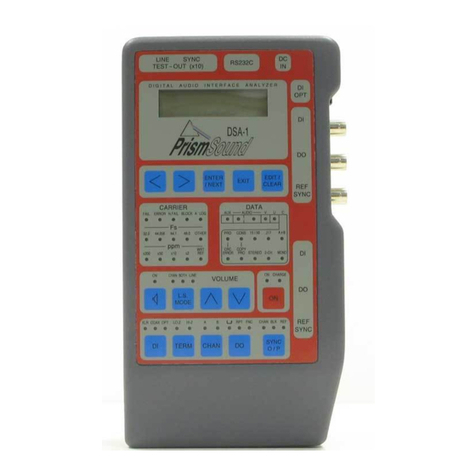
2.1. Equipment overview
The layout of the DSA-1 controls and connections is designed for maximum ease of use
in both 'hand-held' and 'desk-top' situations.
In the centre of the front panel are located 'CARRIER' and 'DATA' display panels,
wherein a number of LED indicators normally provide constant monitoring of the basic
properties of the signal-under-test.
Below these panels are a row of four keys for control of the monitoring D/A converter
(DAC) and the red [ON] key. At the bottomof the front panel are a row of I/O selection
controls which affect the operating modes of the DSA-1's connectors.
The upper part of the front-panel contains an LCD display and its associated keys
which provide a menu system for making detailed measurements, running Test
Sequences, and controlling all additional functions of the DSA-1.
The main test I/O connectors are situated along the right-hand edge of the DSA-1, and
the auxiliary-function connectors are along the front edge. All these connectors are
legended around the edge of the front panel. The headphone socket is at the near
right-hand corner of the DSA-1.

Prism Operation Manual Issue 2.00
Page 2.2
2.2. Turning on the DSA-1
The DC input connector is on the front right-hand corner of the instrument under the
front-panel legend `DC IN'. Connect the DC adapter to the mains, and plug its output
into the unit's DC input connector.
Switch on the DSA-1 by pressing the [ON] key. If all is well the 'CHARGE' indicator will
light, followed shortly afterwards by the 'ON' indicator.
The display will contain the message:
Prism Sound
DSA-1 sw2.0 hwC
This message indicates that version 2.0 of the DSA-1 firmware is installed, and that the
DSA-1 hardware is at revision C. If a later version of firmware has been installed, at
the factory or elsewhere, the current version will be displayed instead of V2.0 as above.
The READ.ME file on the system software diskette will also contain information about
the current firmware version and revision level.
If battery operation is required, then the battery may first need to be charged; this will
take approximately 12 hours in fast-charge mode. The battery charge mode must first
be selected and this is described in section 6.9.5. While operating on external DC
power the unit will trickle-charge the battery.
If no test input is connected (and if the Generator is off), all indicators in the DATA
display panel will be unlit and in the CARRIER panel the 'FAIL' indicator will be lit.
If the behaviour of your DSA-1 is not as described above then contact Prism Media
Products or your distributor.

Prism Operation Manual Issue 2.00
Page 2.3
2.3. Connecting a digital audio input
Connect a digital audio source to the appropriate DSA-1 input connector. If possible,
use a source which allows some control of the audio output. Ideally, use a digital audio
test generator, such as the Prism Sound Dscope system, which will allow sufficient
degree of control to demonstrate most of the features of the DSA-1. Alternatively, basic
operation can be demonstrated using a simple CD player (with a digital output), or a
DAT recorder.
If you wish to connect a consumer source via an RCA (phono) cable, you will need to
plug in one of the phono-to-BNC adapters (provided with the DSA-1) to the co-axial `DI'
input.
Having connected a suitable source, select the required input format (optical, co-axial
or balanced) using the [DI] selector on the lower left of the DSA-1 control panel. The
'FAIL' LED on the CARRIER panel should extinguish and a sampling frequency and
accuracy should be indicated.
The DATA panel shows the basic activity of the audio and status data; if a 16-bit source
has been chosen only the main 'AUDIO' indicator should be lit, whilst a 24-bit source
would cause both 'AUDIO' LEDs plus the 'AUX' LED to be lit. Turning the source off
may cause the 'AUDIO' and 'AUX' LEDs to be extinguished, unless a DC offset or
dither signal remains (as is often the case with CD sources).
If you are using a Prism Sound Dscope system as a test source, try incrementing the
generator word-length from its minimum setting (12-bit) to its maximum (24-bit) and
observe the bit-activity indicators. If you are using a CD or DAT player, the 'AUX'
indicator and the left-hand 'AUDIO' indicator should be off, representing a 16-bit
source.
The 'V' indicator is normally unlit unless the source is 'invalid' (such as when a CD
player is stopped or paused). The 'U' LED is lit if there is activity in the User channel.
The lower part of the DATA panel contains a brief display of the meaning of the
incoming Channel Status bits.

Prism Operation Manual Issue 2.00
Page 2.4
2.4. Some basic tests
This section assumes that the settings of the DSA-1 are the factory defaults. If you
have difficulty in reproducing the results below, please try again after instating the
default settings via menu 9.3.
Press the [LS] key so that its 'ON' indicator is lit, and set the [L.S. MODE] to 'BOTH'.
A mono mix of the two audio channels should now be audible from the DSA-1's
loudspeaker. It may be necessary to operate the [
Y
Y
]and [
Z
Z
]keys to obtain the correct
volume level.
Press the [EXIT] key a few times to ensure that you are at the top level of the menu
system, and then use the [<] and [>] keys until the display shows:
Select Mode:
1. Carrier Tests
Now press the [ENTER/NEXT] key, and the display will show:
1. Carrier Tests
1.1. fs Freq
On pressing the [ENTER/NEXT] key again, the measured sampling rate of the test
signal is displayed, along with its accuracy in ppm (parts per million), for example:
fs = 44100.44 Hz
Acc = +10 ppm
Now press the [EXIT] key followed by the [>] key. The display shows:
1. Carrier Tests
1.2. fs Jitter
Enter the sampling-rate jitter test mode by pressing [ENTER/NEXT], and the result is
displayed, for example:
fs Jitter [P-P]
= 4.3ns fc=1k5
These few basic steps are intended to give an introduction to the workings of the DSA-
1. Later sections of this manual cover all DSA-1 operations in detail.

Prism Operation Manual Issue 2.00
Page 2.5
2.5. Running an automatic Test Sequence
This section assumes that the settings of the DSA-1 are the factory defaults. If you
have difficulty in reproducing the results below, please try again after instating the
default settings via menu 9.3.
Press the [EXIT] key a few times to ensure that you are at the top level of the menu
system, and then use the [<] and [>] keys until the display shows:
Select Mode:
3. Test Sequence
Now press the [ENTER/NEXT] key followed by the [>] key, and the display shows:
3. Test Sequence
3.2. Select
Press the [ENTER/NEXT] key again, and use the [>] key to select the Test Sequence
which is appropriate to your test signal. If the DATA panel shows 'PRO' select:
Selected: Sys03
General Pro Test
Or if the DATA panel shows 'CONS' select:
Selected: Sys02
Consumer Test
Now press the [EXIT] key, followed by the [<] key to bring you to the 'Run' menu option.
Press the [ENTER/NEXT] key to run your selected Test Sequence. You should see
a series of messages describing the various parts of the test as they happen. If all is
well, the LCD should eventually show:
General Pro Test
* Tests complete
Or, if you were running the Consumer Sequence:
Consumer Test
* Tests complete
On the other hand, you may discover that something is wrong with your test signal, in
which case an error message is displayed instead. This may seem surprising but, in

Prism Operation Manual Issue 2.00
Page 2.6
fact, it is not very unusual since many digital audio signals currently in use do not
completely conform.
Section 6.3. includes more details about selecting and running Test Sequences.
2.6. Try the Signal Generator
This section assumes that the settings of the DSA-1 are the factory defaults. If you
have difficulty in reproducing the results below, please try again after instating the
default settings via menu 9.3.
First, switch on the Signal Generator by pressing the [DO] key twice to light the 'FNC'
LED. The 'Fs' section of the CARRIER panel should now indicate the sampling rate as
'48.0' with no 'ppm' indicators lit: In the 'FNC' mode, the 'Fs' LEDs indicate the basic
sampling rate of the Generator and not the test input.
Connect the XLR or coaxial test output ('DO') of the DSA-1 to a device capable of
monitoring a digital audio input. You can use the DSA-1 for this by connecting one of
the 'DO' outputs to the corresponding 'DI' input using an XLR or coaxial cable. In this
case, make sure that the loudspeaker is turned on (by pressing the [LS] key to
illuminate its 'ON' indicator) and that the appropriate data input is selected (with the
[DI] key in the lower left-hand corner). When this is accomplished, the 'FAIL' LED will
go out and the Signal Generator's 1kHz tone will be heard on the loudspeaker.
Press the [EXIT] key a few times to return to the top level of the menu system, and then
the [>] key a number of times until you see:
Select Mode:
4. Generator
Press [ENTER/NEXT] and then [>] key a number of times until you get to:
4. Generator
4.4. Audio Param
Pressing [ENTER/NEXT] again will display the Audio Parameters menu:
Ù
A&B:ON -14dB
Wrd:24b 1000Hz
Operating the [<] or [>] keys adjusts the indicated parameter, in this case turning the
generator on and off. The 'A&B' indication means that adjustments are currently set to
operate on both output channels.

Prism Operation Manual Issue 2.00
Page 2.7
Pressing the [ENTER/NEXT] key twice moves the flashing arrow onto the generator
amplitude parameter, initially set at -14dBFS. Operating the [<] or [>] keys now
reduces or increases the amplitude setting. The generator mutes while the setting is
being adjusted, then turns on at the new amplitude. The [EDIT/CLEAR] key is used
to return to default settings where appropriate, in this case re-setting an amplitude of
-14dBFS. This amplitude is often used as a standard line-up level, being +4dB above
-18dBFS.
Pressing the [ENTER/NEXT] key again moves the flashing arrow onto the generator
frequency parameter, initially set at 1000Hz. Operating the [<] or [>] keys now adjusts
the frequency in a similar way, with [EDIT/CLEAR] re-setting to the default 1000Hz if
required.
This is a very brief introduction to the Signal Generator, which has a wide capability.
The full details of the Signal Generator are explained in section 6.4.

Prism Operation Manual Issue 2.00
Page 3.1
3. DSA-1 I/O connectors
Around the periphery of the membrane panel on the front and right-hand edges are
several grey panels indicating the function of the connectors located immediately
below.
The following connectors are provided:
•DI (digital audio inputs) for measurement:
•110
6
balanced
•75
6
coaxial
•OPTical TOSLINK
•DO (digital audio outputs) for loop-through, re-clocking and Generator
modes:
•110
6
balanced
•75
6
coaxial
•REF SYNC inputs (AES11/IEC958 format or 'Wordclock'):
•110
6
balanced input
•75
6
coaxial input
•Headphone socket
•TEST-OUT connections for oscilloscope:
•LINE test output
•SYNC test output
•RS-232 serial port
•DC IN connector
Table of contents
Other Prism Sound Controllers manuals
